BRAKE CONTROL SYSTEM
-
FUNCTION OF MAIN COMPONENTS
-
ABS with EBD
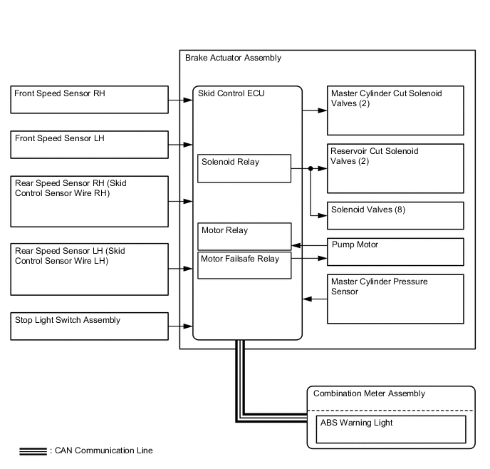
Component Function Brake Actuator Assembly Skid Control ECU Judges the vehicle driving condition based on the signals from each sensor, and sends brake control signals to the brake actuator. Solenoid Valve Changes the fluid path based on the signals from the skid control ECU during the operation of the ABS with EBD, in order to control the fluid pressure that is applied to the wheel cylinders. Pump Motor Drives the pumps inside the brake actuator. Solenoid Relay Supplies power to the solenoid valves. Motor Relay Supplies power to the motor. Front Speed Sensor RH Detect the wheel speed of each of the 4 wheels. Front Speed Sensor LH Rear Speed Sensor RH (Skid Control Sensor Wire RH) Rear Speed Sensor LH (Skid Control Sensor Wire LH) Stop Light Switch Assembly Detects the brake pedal depressing signal. Parking Brake Switch Assembly Detects when the parking brake lever is pulled up. Brake Master Cylinder Sub-assembly Brake Fluid Level Warning Switch Detects the brake fluid level. Main Body ECU (Multiplex Network Body ECU) Transmits the parking brake switch signal to the skid control ECU. Combination Meter Assembly ABS Warning Light Lights up to alert the driver when the skid control ECU detects a malfunction in the ABS. Brake Warning Light
-
Lights up together with ABS warning light to alert the driver when the skid control ECU detects the malfunction not only in the ABS but also in the EBD.
-
Lights up to alert the driver when the brake fluid level is low.
-
Lights up to inform the driver when the parking brake lever is pulled up or the parking brake pedal is depressed.
-
-
ABS with EBD, Brake Assist, TRC, VSC and Hill-start Assist Control
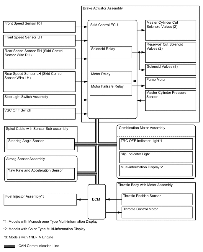
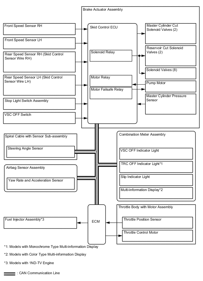
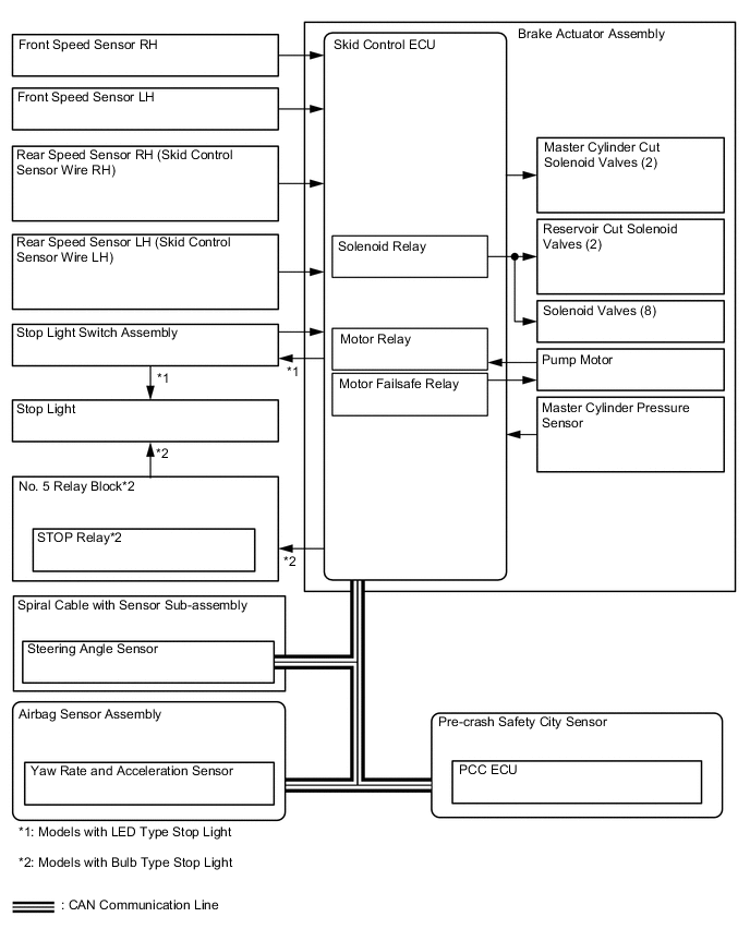
Component Function Brake Actuator Assembly Skid Control ECU Judges the vehicle driving condition based on the signals from each sensor, and sends brake control signals to the brake actuator. Solenoid Valve Changes the fluid path based on the signals from the skid control ECU during the operation of the ABS with EBD, Brake Assist, TRC, VSC and Hill-start Assist Control, in order to control the fluid pressure that is applied to the wheel cylinders. Master Cylinder Cut Solenoid Valve Pump Motor Drives the pumps inside the brake actuator. Solenoid Relay Supplies power to the solenoid valves. Motor Relay Supplies power to the motor. Motor Failsafe Relay Cuts the power to the motor when the motor relay malfunctions. Master Cylinder Pressure Sensor Assembled in the brake actuator, detects the master cylinder pressure. Spiral Cable with Sensor Sub-assembly Steering Angle Sensor Detects the steering direction and angle of the steering wheel. Airbag Sensor Assembly Yaw Rate and Acceleration Sensor Detects the yaw rate and the longitudinal and lateral acceleration and deceleration of the vehicle body. Front Speed Sensor RH Detect the wheel speed of each of the 4 wheels. Front Speed Sensor LH Rear Speed Sensor RH (Skid Control Sensor Wire RH) Rear Speed Sensor LH (Skid Control Sensor Wire LH) Parking Brake Switch Assembly Detects when the parking brake lever is pulled up. Brake Master Cylinder Sub-assembly Brake Fluid Level Warning Switch Detects the brake fluid level. VSC OFF Switch Enables the driver to select the Normal Mode, TRC OFF mode or VSC OFF mode. Main Body ECU (Multiplex Network Body ECU) Transmits the parking brake switch signal to the skid control ECU. Stop Light Switch Assembly
-
Detects brake pedal operation.
-
Turns on the stop lights during pre-crash braking control operation.*1, *2
No. 5 Relay Block*1, *3 STOP Relay Illuminates the stop lights in accordance with the signals from the skid control ECU. Pre-crash Safety City Sensor*1 PCC ECU The PCC ECU judges whether collision is imminent, and makes a request for brake control to the skid control ECU. ECM
-
Sends the throttle position signal, accelerator pedal position signal engine speed signal to the skid control ECU.
-
Based on the signals receives from the skid control ECU, controls the engine output.
Combination Meter Assembly ABS Warning Light Lights up to alert the driver when the skid control ECU detects a malfunction in the ABS. Brake Warning Light
-
Lights up together with ABS warning light to alert the driver when the skid control ECU detects the malfunction not only in the ABS but also in the EBD.
-
Lights up to alert the driver when the brake fluid level is low.
-
Lights up to inform the driver when the parking brake lever is pulled up.
Slip Indicator Light
-
Lights up to alert the driver in the event of malfunction of the TRC, VSC or the Hill-start Assist Control.
-
Blinks to inform the driver when the TRC or VSC operates.
TRC OFF Indicator Light*4 Lights up to inform the driver of TRC OFF mode or VSC OFF mode being selected. VSC OFF Indicator Light Lights up to inform the driver of VSC OFF mode being selected. Multi-information Display*5 Displays an information message when TRC OFF mode is selected. Hazard Warning Switch Transmits a hazard warning light on/off request to the combination meter assembly. *1: Models with Toyota safety sense
*2: Models with LED type stop light
*3: Models with bulb type stop light
*4: Models with monochrome type multi-information display
*5: Models with color type multi-information display
-
-
-
OPERATING CONDITION
-
Emergency Brake Signal
-
Emergency brake signal operating conditions are as shown in the following table.
Activating Conditions When all of the following conditions are met, the emergency brake signal starts operating
-
Vehicle speed is over 55 km/h (34 mph).
-
Driver is depressing the brake pedal.
-
Emergency braking is detected from the vehicle deceleration.
Deactivating Condition When any of the following conditions is met, emergency brake signal stops operating
-
Driver has released the brake pedal.
-
Emergency braking is no longer detected from the vehicle deceleration.
-
Driver has pressed the hazard warning switch.
-
-
-
-
SYSTEM CONTROL
-
Control List
-
The brake control system (ABS with EBD) have the following controls:
Control Outline Anti-lock Brake System (ABS) The ABS helps prevent the wheels from locking when the brakes are applied firmly or when braking on a slippery surface. Electronic Brake Force Distribution (EBD) The EBD control utilizes ABS, realizing proper brake force distribution between the front and rear wheels in accordance with the driving conditions. In addition, during braking while cornering, it also controls the brake forces of the right and left wheels, helping maintain vehicle stability. Brake Assist The primary purpose of the Brake Assist is to provide an auxiliary brake force to assist the driver who cannot generate a large brake force during emergency braking, thus helping draw the vehicle's brake performance. -
The brake control system (ABS with EBD, Brake Assist, TRC, VSC and Hill-start Assist Control) have the following controls:
Control Outline Anti-lock Brake System (ABS) The ABS helps prevent the wheels from locking when the brakes are applied firmly or when braking on a slippery surface. Electronic Brake Force Distribution (EBD) The EBD control utilizes ABS, realizing proper brake force distribution between the front and rear wheels in accordance with the driving conditions. In addition, during braking while cornering, it also controls the brake forces of the right and left wheels, helping maintain vehicle stability. Brake Assist The primary purpose of the Brake Assist is to provide an auxiliary brake force to assist the driver who cannot generate a large brake force during emergency braking, thus helping draw the vehicle's brake performance. Traction Control (TRC) The TRC helps prevent the drive wheels from slipping if the driver depresses the accelerator pedal excessively when starting off or accelerating on a slippery surface. Vehicle Stability Control (VSC) The VSC helps prevent the vehicle from slipping sideway as a result of strong front wheel skid or strong rear wheel skid during cornering. Engine Output Control during TRC or VSC Operation Transmits an engine output control signal from the skid control ECU to the ECM to limit the engine output while the TRC or VSC is being activated. Hill-start Assist Control When starting uphill, this control maintains the brake hydraulic pressure to the 4 wheels, in order to momentarily prevent the vehicle from descending backward. Brake Control (Pre-crash Safety System Operating)* When the PCC ECU determines the collision is imminent, the skid control ECU activates the pre-crash brake assist or the pre-crash brake according to the signal from the PCC ECU. Emergency Brake Signal In the case of emergency braking, the emergency brake signal flashes the hazard warning lights to alert the drivers in following vehicles. *1: Models with Toyota safety sense
-
-
Anti-lock Brake System (ABS)
-
The ABS prevents the wheels from locking during sudden braking or braking on a slippery surface. This provides the proper braking force when the vehicle slips, thus ensuring vehicle stability and excellent braking performance.
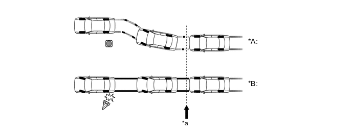
Text in Illustration *A With ABS *B Without ABS *a Brake Operation - -
-
-
Electronic Brake Force Distribution (EBD)
-
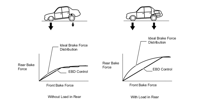
The distribution of the brake force, which was performed mechanically in the past, is now performed under electrical control of the skid control ECU, which controls the braking force in accordance with the vehicle's driving conditions.
-
If the brakes are applied while the vehicle is moving straight forward, the transfer of the load reduces the weight that is applied to the rear wheels. The skid control ECU determines this condition by way of the signals from the speed sensor, and the brake actuator regulates the distribution of the brake force of the rear wheels to optimally control. For example, the amount of the brake force that is applied to the rear wheels during braking varies depending on whether the vehicle is carrying load or not. The amount of the brake force that is applied to the rear wheels also varies in accordance with the extent of the deceleration. Thus, the distribution of the brake force to the rear is optimally controlled in order to effectively utilize the braking force of the rear wheels under these conditions.
-
When the brakes are applied while the vehicle is cornering, the load that is applied to the inner wheel decreases as the load to the outer wheel increases. The skid control ECU determines this condition by way of the signals from the speed sensor, and the brake actuator regulates the brake force in order to optimally control the distribution of the brake force to the inner wheel and outer wheel.

Text in Illustration *a Control Moment - - 
Brake Force - -
-
-
Brake Assist
-
The Brake Assist in combination with the ABS helps enhance the vehicle's brake performance.
-
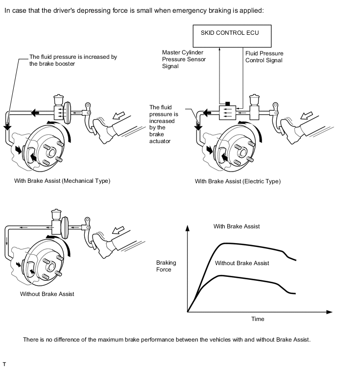
The Brake Assist interprets a quick push of the brake pedal as emergency braking and supplements the brake force applied if the driver has not depressed hard enough the brake pedal. In emergencies, drivers, especially inexperienced ones, often panic and do not apply sufficient pressure on the brake pedal.
-
A key feature of Brake Assist is that the timing and the degree of braking assistance are designed to help enhance that the driver dose not discern anything unusual about the braking operation. When the driver intentionally eases up on the brake pedal, the system reduces the amount of assistance it provides.
-
The mechanical type Brake Assist uses the brake assist mechanism in the brake booster to mechanically activate the brake booster function in order to increase the brake force.
-
In the electrical type brake assist, based on the signals from the master cylinder pressure sensor, the skid control ECU calculates the speed and the amount of the brake pedal application and then determines the intention of the driver to make an emergency braking. If the skid control ECU determines that the driver intends emergency braking, this function activates the brake actuator to increase the brake fluid pressure, which increases the braking force.
-
-
Traction Control (TRC)
-
If the driver depresses the accelerator pedal aggressively when initially accelerating or when accelerating on a slippery surface, the drive wheels could slip due to the excessive amount of torque that is generated. By applying hydraulic brake control to the drive wheels and regulating the throttle to control the engine output, the TRC helps minimize the slippage of the drive wheels, thus generating the drive force that is appropriate for the road surface conditions.
-
For example, a comparison may be made between two vehicles, one with the TRC and the other without. If the driver of each vehicle operates the accelerator pedal in a rough manner while driving over a surface with different surface friction characteristics, the drive wheel on the slippery surface could slip as illustrated. As a result, the vehicle could become unstable. However, when the vehicle is equipped with the TRC, the skid control ECU instantly determines the state of the vehicle and operates the brake actuator in order to apply the brakes to the slipping drive wheel. Furthermore, the ECM receives the signals from the skid control ECU and regulates the throttle in order to control the engine output. Thus, the system can constantly maintain a stable vehicle posture.
Text in Illustration *A Without TRC *B With TRC *1
-
Brake Actuator Assembly
-
Skid Control ECU
*2
-
ECM
-
Regulating the throttle to control the engine output (1KR-FE or 1NR-FE)
-
Regulating the fuel injector to control the engine output (1ND-TV)
*a Driving condition on road with different surface friction characteristics *b Slippery Surface *c Brake the slipping drive wheel - - -
-
-
Vehicle Stability Control (VSC)
-
The following are two examples that can be considered as circumstances in which the tires exceed their lateral grip limit. The VSC is designed to help control the vehicle behavior by controlling the motive force and the brakes at each wheel when the vehicle is under one of the conditions indicated below.
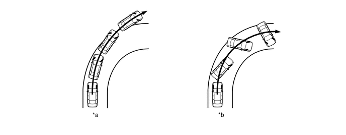
Text in Illustration *a Front Wheel Skid Tendency *b Rear Wheel Skid Tendency -
To determine the condition of the vehicle, sensors detect the steering angle, vehicle speed, vehicle's yaw rate, and the vehicle's lateral acceleration, which are then calculated by the skid control ECU.
-
Whether or not the vehicle is in the state of front wheel skid is determined by the difference between the target yaw rate and the vehicle's actual yaw rate. When the vehicle's actual yaw rate is smaller than the yaw rate (a target yaw rate that is determined by the vehicle speed and steering angle) that should be rightfully generated when the driver operates the steering wheel, it means the vehicle is making a turn at a greater angle than the locus of travel. Thus, the skid control ECU determines that there is a large tendency to front wheel skid.

Text in Illustration *a Actual Locus of Travel (Actual Yaw Rate) *b Locus of Travel (Based on the Target Yaw Rate) -
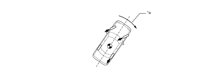
Whether the vehicle is in the state of the rear wheel skid or not is determined by the values of the vehicle's slip angle and the vehicle's slip angular velocity (time-dependent changes in the vehicle's slip angle). When the vehicle's slip angle and the slip angular velocity are large, the skid control ECU determines that the vehicle has a large rear wheel skid tendency.

Text in Illustration *a Actual Locus of Travel (Actual Yaw Rate) *b Locus of Travel (Based on the Target Yaw Rate) *c Slip Angle - - -
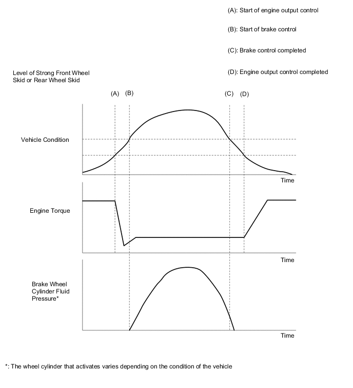
When the skid control ECU determines that the vehicle has a tendency to front wheel skid or rear wheel skid, it decreases the engine output and applies the brake of a front or rear wheel to control the vehicle's yaw moment. The basic operation of the VSC is described below. However, the control method differs depending on the vehicle's characteristics and driving conditions.
-
When the skid control ECU determines that there is a large front wheel skid tendency, it takes countermeasures in accordance with the extent of that tendency. The skid control ECU controls the engine output and applies the brakes of the front wheels and rear wheel of the inner circle of the turn in order to help restrain the front wheel skid tendency.
Text in Illustration (Making a Right Turn:) *a Control Moment - - Brake Force - - -
When the skid control ECU determines that there is a large rear wheel skid tendency, it takes countermeasures in accordance with the extent of that tendency. It applies the brakes of the front and rear wheels of the outer circle of the turn, and generates an outward moment of inertia in the vehicle, in order to restrain the rear wheel skid tendency. Along with the reduction in the vehicle speed caused by the braking force, excellent vehicle stability is enhanced.

Text in Illustration (Making a Right Turn:) *a Control Moment - - Brake Force - -
-
-
Engine Output Control during TRC or VSC Operation
-
During the TRC or VSC operation, the skid control ECU outputs the engine output control signal to the ECM. Upon receiving this signal, the ECM inhibits the engine output.
-
-
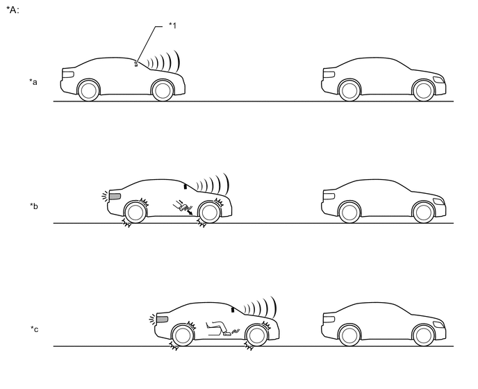
Hill-start Assist Control
-
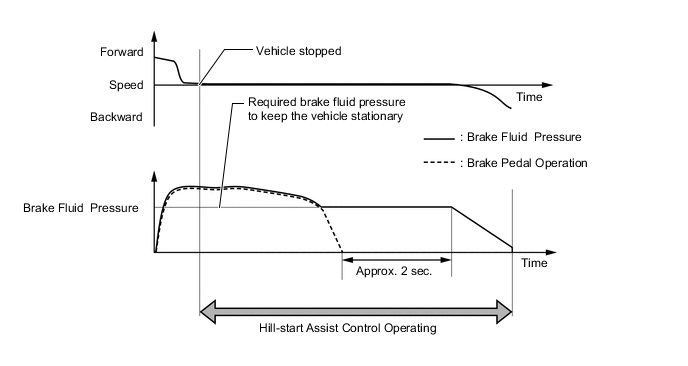
When the vehicle starts off on a steep or slippery hill, it may start to descend backward while the driver switches from the brake pedal to the accelerator pedal, thus making it difficult for the vehicle to start off. To prevent this from occurring, the Hill-start Assist Control temporarily (approximately 2 seconds at the maximum) applies the brakes to the 4 wheels in order to prevent the vehicle from descending backward.
-
Without the hill-start assist control, the driver must quickly and precisely switch from the brake pedal to the accelerator pedal. With the hill-start assist control, however, the driver may start off easily and operate the pedal in a relaxed manner, because the hill-start assist control prevents the vehicle from descending backward.
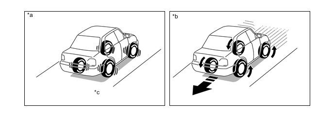
*a Models with Hill-start Assist Control *b Models without Hill-start Assist Control *c Prevents vehicle from descending backward by controlling brakes. - - -
Hill-start Assist Control Activation Conditions
-
The skid control ECU judges if the vehicle is on an uphill incline based on signals from the deceleration sensor, and activates Hill-start Assist Control when the vehicle is started with all of the following conditions met.
Control Activation Conditions
-
The shift lever is in any position other than P or N (Forward climbing and backward climbing).*1
-
The shift lever is in a position other than R when starting off forward on an upward incline or in R when starting off backward on an upward incline.*2
-
The vehicle is at a standstill.
-
The accelerator pedal is not depressed.
-
The parking brake is released.
*1: Models with CVT
*2: Models with manual transaxle
-
-
Hill-start Assist Control Cancelation Conditions
-
If any of the following conditions is met, Hill-start Assist Control operation is canceled.
Control Cancelation Conditions
-
The shift lever is moved to P or N.*1
-
The shift lever is shifted to R when starting off forward on an upward incline or from R when starting off backward on an upward incline.*2
-
The accelerator pedal is depressed.
-
The parking brake is operated.
-
Approximately 2 seconds elapse since the operation started.
*1: Models with CVT
*2: Models with manual transaxle
-
-
-
Outline of Brake Control (Pre-crash Safety System Operating)
-
If the PCC ECU determines that the possibility of a collision is high, the ECU sends the pre-crash brake assist request signal to the skid control ECU. Upon receiving the signal, the skid control ECU switches the brake assist to standby mode. When the driver depresses the brake pedal, the skid control ECU operates the brake assist based on the master cylinder pressure sensor.
-
If the PCC ECU determines a collision is unavoidable, the ECU sends the pre-crash brake request signal to the skid control ECU. The skid control ECU then activates the brake actuator as a pre-crash brake control and decelerates the vehicle. Thus, the system helps to lessen impact in collision.
Text in Illustration *A Brake Operation - - *1
-
Pre-crash Safety City Sensor
-
PCC ECU
- - *a Brake Assist Standby Mode *b Brake Assist Operation *c Brake Operation - - -
-
-
Emergency Brake Signal
-
The emergency brake signal automatically flashes the hazard warning lights in the case of emergency braking in order to reduce the risk of being rear ended by a following vehicle.
-
The skid control ECU detects the vehicle condition and braking operation using the speed sensors and stop light switch assembly.
-
If emergency braking is detected based on these various signals, the skid control ECU sends a signal to the combination meter assembly to flash the hazard warning lights.
-
-
-
FUNCTION
-
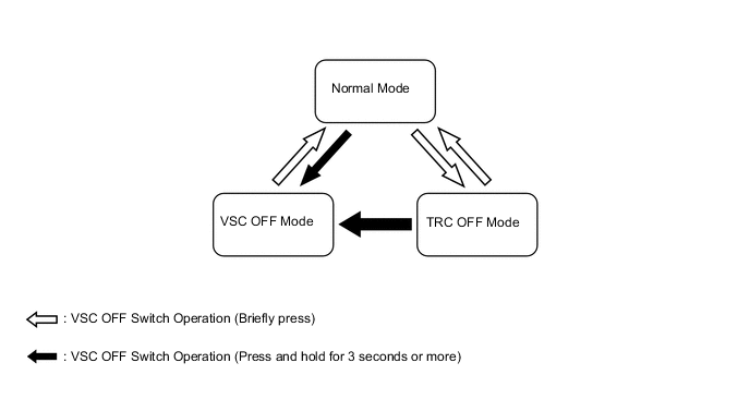
VSC OFF Switch (Models with ABS with EBD, Brake Assist, TRC, VSC and Hill-start Assist Control)
-
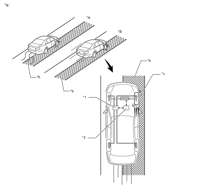
The operation of the VSC and TRC functions can be stopped by the VSC OFF switch. While the vehicle is running off the shoulder of the road or running on the dirt road, the engine output control is stopped to maintain drive torque.
-
The VSC OFF switch can select the 3 modes (Normal Mode, TRC OFF Mode, VSC OFF Mode). When the VSC OFF switch is pressed briefly, TRC OFF Mode is entered and the TRC function will be disabled. When the VSC OFF switch is pressed and held for 3 seconds or more, VSC OFF Mode is entered and the TRC and VSC functions will be disabled.
-
After the power source is turned off in the TRC OFF or VSC OFF, turning the power source on again selects the Normal Mode. The system also enters Normal Mode automatically when the vehicle speed increases.
-
The operations of the brake control functions in each mode are as follows:
Mode Brake Control Function Combination Meter Assembly TRC VSC VSC OFF Indicator Light TRC OFF Indicator Light*1 Multi-information Display*2 Normal Mode Controllable Controllable - - - TRC OFF Mode Not Controllable Controllable - Illuminates TRC OFF message is displayed VSC OFF Mode Not Controllable Not Controllable*3 Illuminates Illuminates TRC OFF message is displayed *1: Models with monochrome type multi-information display.
*2: Models with color type multi-information display.
*3: The control is effected during braking or while the yaw rate is large.
-
-
-
CONSTRUCTION
-
Brake Actuator Assembly
-
The brake actuator assembly consists of the actuator portion and skid control ECU.
-
The actuator portion regulates the hydraulic brake pressure to each wheel cylinder.
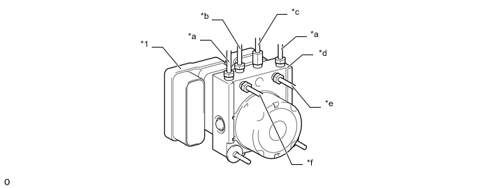
Text in Illustration (ABS with EBD on Models:) *1 Skid Control ECU - - *a From Master Cylinder *b To Front Wheel Cylinder LH *c To Front Wheel Cylinder RH *d Actuator Portion *e To Rear Wheel Cylinder LH *f To Rear Wheel Cylinder RH 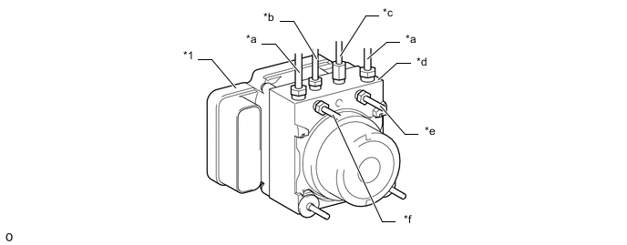
Text in Illustration (ABS with EBD, Brake Assist, TRC and VSC on Models:) *1 Skid Control ECU - - *a From Master Cylinder *b To Front Wheel Cylinder LH *c To Front Wheel Cylinder RH *d Actuator Portion *e To Rear Wheel Cylinder LH *f To Rear Wheel Cylinder RH -
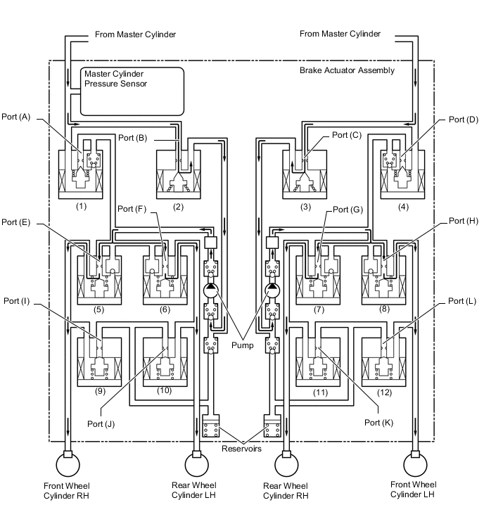
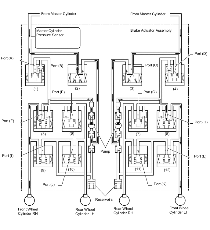
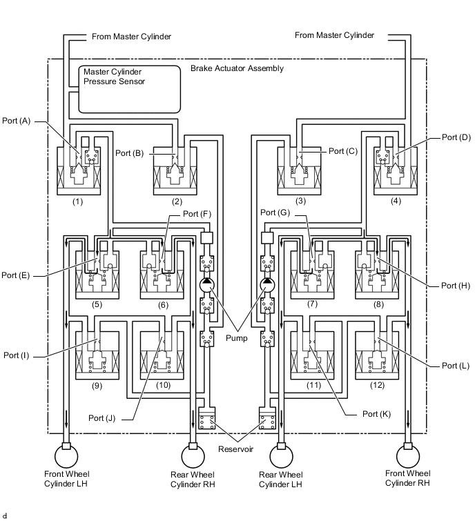
The brake actuator assembly is constructed with the following hydraulic circuit:
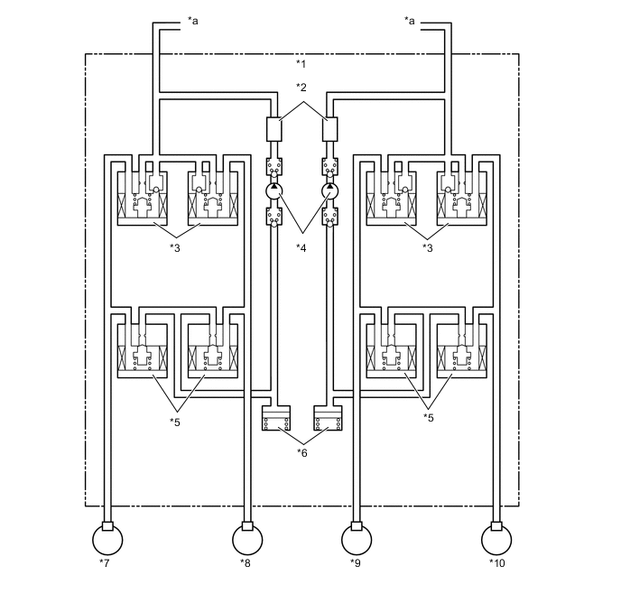
Text in Illustration (ABS with EBD on Models:) *1 Brake Actuator Assembly *2 Damping Chamber *3 Pressure Holding Solenoid Valve *4 Pump *5 Pressure Reduction Solenoid Valve *6 Reservoir *7 Front Wheel Cylinder LH *8 Rear Wheel Cylinder RH *9 Front Wheel Cylinder RH *10 Rear Wheel Cylinder LH *a From Master Cylinder - - 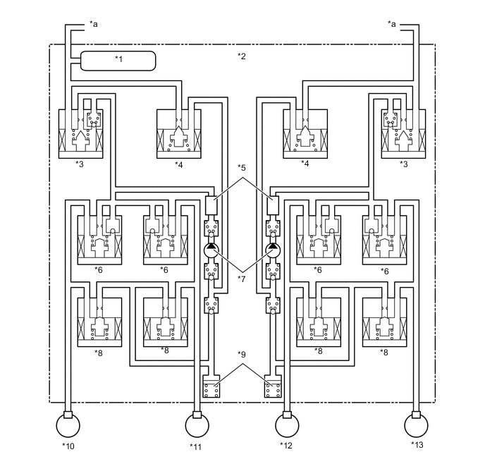
Text in Illustration (ABS with EBD, Brake Assist, TRC and VSC on Models:) *1 Master Cylinder Pressure Sensor *2 Brake Actuator Assembly *3 Master Cylinder Cut Solenoid Valve *4 Reservoir Cut Solenoid Valve *5 Damping Chamber *6 Pressure Holding Solenoid Valve *7 Pump *8 Pressure Reduction Solenoid Valve *9 Reservoir *10 Front Wheel Cylinder RH *11 Rear Wheel Cylinder LH *12 Rear Wheel Cylinder RH *13 Front Wheel Cylinder LH - - *a From Master Cylinder - -
-
-
Speed Sensor
-
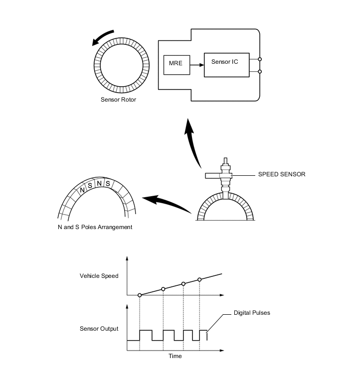
An active type speed sensor is used. This sensor contains a sensor IC.
-
The sensor rotor, which consists of N and S poles that are arranged in a circle, is integrated with the hub bearing inner race.
-
An active type speed sensor uses a sensor IC to detect magnetic field changes caused when the sensor rotor rotates, and the sensor outputs the detected information to the skid control ECU as digital pulses.
-
To detect the vehicle speed, the frequency of the output pulses is used. Because the active type sensor outputs digital pulses, it can detect vehicle speeds even when the vehicle is nearly stationary.
-
-
Yaw Rate and Acceleration Sensor (Models with ABS with EBD, Brake Assist, TRC and VSC)
-
The yaw rate and acceleration sensor is built into the airbag sensor assembly.
-
The yaw rate sensor detects acceleration in the horizontal forward-backward and left-right directions using the signals from two acceleration sensors, and transmits signals to the skid control ECU.
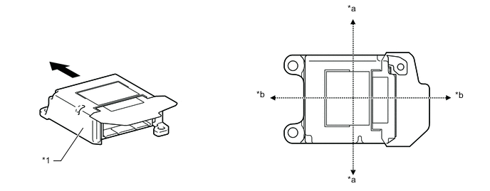
Text in Illustration *1 Airbag Sensor Assembly
-
Yaw Rate and Acceleration Sensor
- - *a Left-right Direction *b Forward-backward Direction Front - - Note
After replacing the airbag sensor assembly, or the skid control ECU, initialization of the yaw rate sensor is required. For the actual procedure, refer to the Repair Manual.
-
-
-
Steering Angle Sensor (Models with ABS with EBD, Brake Assist, TRC and VSC)
-
The steering angle sensor detects the steering direction and angle, and sends this signal to the skid control ECU.
-
The steering angle sensor contains two sets of magnetic reluctance elements that detect the rotational movement of a magnet that is built into the detection gear. Thus, the sensor detects the changes that occur in the magnetic reluctance elements along with the rotational movement of the detection gear, in order to detect the rotational movement of the steering wheel.
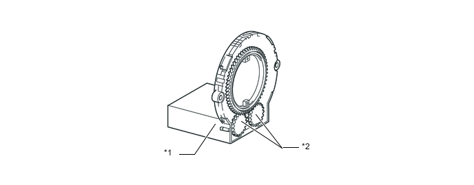
Text in Illustration *1 Steering Angle Sensor *2 Detection Gear Note
Do not remove the steering angle sensor from the spiral cable. If there is a malfunction in the steering angle sensor, replace the spiral cable with steering angle sensor.
-
-
-
OPERATION
-
ABS with EBD
-
Based on the signals received from the 4 speed sensors, the skid control ECU calculates each wheel speed and deceleration, and checks wheel slipping conditions. According to the slipping condition, the skid control ECU controls the pressure holding valve and pressure reduction valve in order to adjust the fluid pressure of the each wheel cylinder in the following 3 modes: pressure reduction, pressure holding and pressure increase modes.
Not Activated Normal Braking Activated Increase Mode Hydraulic Circuit 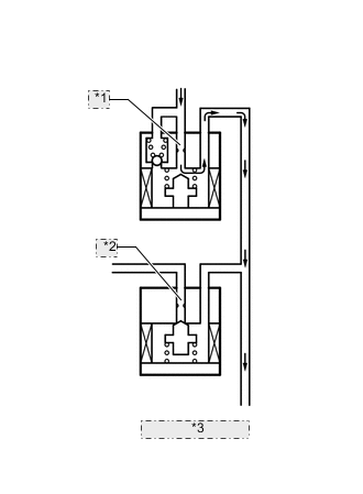
*1 Port A *2 Port B *3 To Wheel Cylinder Pressure Holding Valve (Port A) OFF (Open) Pressure Reduction Valve (Port B) OFF (Closed) Brake Wheel Cylinder Pressure Increased Not Activated - Activated Holding Mode Hydraulic Circuit 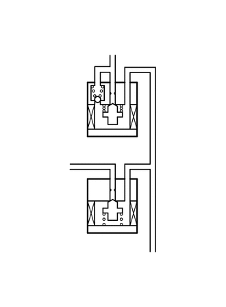
Pressure Holding Valve (Port A) ON (Closed) Pressure Reduction Valve (Port B) OFF (Closed) Brake Wheel Cylinder Pressure Held Not Activated - Activated Reduction Mode Hydraulic Circuit 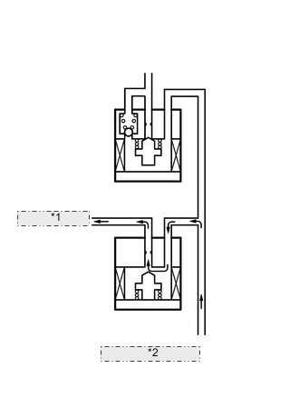
*1 To Reservoir and Pump *2 From Wheel Cylinder Pressure Holding Valve (Port A) ON (Closed) Pressure Reduction Valve (Port B) ON (Open) Brake Wheel Cylinder Pressure Reduced
-
-
Brake Assist (Electrical Type)
-
In the event of emergency braking, the skid control ECU detects the driver's intention based on the speed of the pressure increase in the master cylinder determined by the master cylinder pressure sensor signal. If the skid control ECU judges the need for additional brake assist, pressure is generated by the pump in the brake actuator assembly and directed to the wheel cylinder to apply a greater fluid pressure than the master cylinder.
Item Port Not Activated Activated Master Cylinder Cut Solenoid Valve (1) (A) OFF (Open) ON (Close) (4) (D) OFF (Open) ON (Close) Reservoir Cut Solenoid Valve (2) (B) OFF (Close) ON (Open) (3) (C) OFF (Close) ON (Open) Pressure Holding Solenoid Valve (5) (E) OFF (Open) ← (6) (F) OFF (Open) ← (7) (G) OFF (Open) ← (8) (H) OFF (Open) ← Pressure Reduction Solenoid Valve (9) (I) OFF (Close) ← (10) (J) OFF (Close) ← (11) (K) OFF (Close) ← (12) (L) OFF (Close) ← Pump OFF ON* Tech Tips
*: The solenoid valve controls the hydraulic pressure between "open" and "close" according to the operating condition by adjusting continually.
-
-
TRC
-
The fluid pressure generated by the pump motor is regulated by the master cylinder cut solenoid valve to the required pressure. Thus, the wheel cylinders of the drive wheels are controlled in the following 3 modes: pressure reduction, pressure holding, and pressure increase modes to control the slippage of the drive wheels. The diagram below shows the hydraulic circuit in the pressure increase mode when the TRC is activated. The pressure holding solenoid valve and the pressure reduction solenoid valve are turned on/off according to the ABS with EBD operation pattern.
-
By way of example, the brake hydraulic circuit under the pressure increase mode of TRC is shown below.
Item Port Not Activated Activated Increase Mode Holding Mode Reduction Mode Master Cylinder Cut Solenoid Valve (1) (A) OFF (Open) ON (Close)* ← OFF (Open) (4) (D) OFF (Open) ON (Close)* ← OFF (Open) Reservoir Cut Solenoid Valve (2) (B) OFF (Close) ON (Open) OFF (Close) ← (3) (C) OFF (Close) ON (Open) OFF (Close) ← Front Brake Pressure Holding Solenoid Valve (5) (E) OFF (Open) ← ← ← (8) (H) OFF (Open) ← ← ← Pressure Reduction Solenoid Valve (9) (I) OFF (Close) ← ← ← (12) (L) OFF (Close) ← ← ← Brake Wheel Cylinder Pressure Right - - Increase Hold Reduce Left - - Increase Hold Reduce Rear Brake Pressure Holding Solenoid Valve (6) (F) OFF (Open) ON (Close) ← ← (7) (G) OFF (Open) ON (Close) ← ← Pressure Reduction Solenoid Valve (10) (J) OFF (Close) ← ← ← (11) (K) OFF (Close) ← ← ← Brake Wheel Cylinder Pressure Right - - - - - Left - - - - - Pump OFF ON ← ← Tech Tips
*: The solenoid valve controls the hydraulic pressure between "open" and "close" according to the operating condition by adjusting continually.
-
-
VSC
-
The VSC, by way of solenoid valves, controls the fluid pressure that is generated by the pump and applies it to the brake wheel cylinder of each wheel in the following 3 modes: pressure reduction, pressure holding, and pressure increase modes. As a result, the tendency to front wheel skid or rear wheel skid is controlled.
-
In the front wheel skid restraining control, the brakes of the front wheels and rear wheel of the inner circle of the turn is applied. Also, depending on whether the brake is on or off and the condition of the vehicle, there are circumstances in which the brake might not be applied to the wheels even if the wheel is targeted for braking. The diagram below shows the hydraulic circuit in the pressure increase mode, as it controls the front wheel skid condition while the vehicle makes a right turn. In other operating modes, the pressure holding valve and the pressure reduction valve are turned on/off according to the ABS with EBD operation pattern.
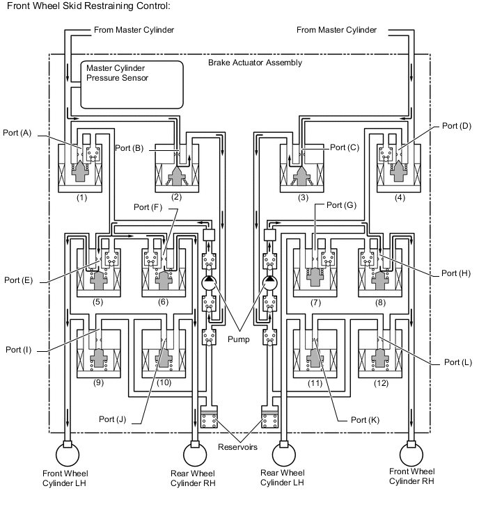
Front Wheel Skid Restraining Control Item Port Not Activated Activated Increase Mode Holding Mode Reduction Mode Master Cylinder Cut Solenoid Valve (1) (A) OFF (Open) ON (Close)* ← ← (4) (D) OFF (Open) ON (Close)* ← ← Reservoir Cut Solenoid Valve (2) (B) OFF (Close) ON (Open) ← ← (3) (C) OFF (Close) ON (Open) ← ← Front Brake Pressure Holding Solenoid Valve (5) (E) OFF (Open) ← ON (Close) ← (8) (H) OFF (Open) ← ON (Close) ← Pressure Reduction Solenoid Valve (9) (I) OFF (Close) ← ← ON (Open) (12) (L) OFF (Close) ← ← ON (Open) Brake Wheel Cylinder Pressure Right - - Increase Hold Reduce Left - - Increase Hold Reduce Rear Brake Pressure Holding Solenoid Valve (6) (F) OFF (Open) ← ON (Close) ← (7) (G) OFF (Open) ← ON (Close) ← Pressure Reduction Solenoid Valve (10) (J) OFF (Close) ← ← ON (Open) (11) (K) OFF (Close) ← ← ← Brake Wheel Cylinder Pressure Right - - Increase Hold Reduce Left - - - - - Pump OFF ON ← ← Tech Tips
*: The solenoid valve controls the hydraulic pressure between "open" and "closed" according to the operating condition by adjusting continually.
-
In the rear wheel skid restraining control, the brakes of the front wheels on the outer circle of the turn are applied. Also, depending on whether the brake is on or off and the condition of the vehicle, there are circumstances in which the brake might not be applied to the wheels even if the wheel is targeted for braking. The diagram below shows the hydraulic circuit in the pressure increase mode, as it controls the rear wheel skid condition while the vehicle makes a right turn. In other operating modes, the pressure holding valve and the pressure reduction valve are turned on/off according to the ABS with EBD operation patterns.
Tech Tips
*: The solenoid valve controls the hydraulic pressure between "open" and "closed" according to the operating condition by adjusting continually.
Rear Wheel Skid Restraining Control Item Port Not Activated Activated Increase Mode Holding Mode Reduction Mode Master Cylinder Cut Solenoid Valve (1) (A) OFF (Open) ON (Close)* ← ← (4) (D) OFF (Open) ON (Close)* ← ← Reservoir Cut Solenoid Valve (2) (B) OFF (Close) ON (Open) ← ← (3) (C) OFF (Close) ON (Open) ← ← Front Brake Pressure Holding Solenoid Valve (5) (E) OFF (Open) ← ON (Close) ← (8) (H) OFF (Open) ON (Close) ← ← Pressure Reduction Solenoid Valve (9) (I) OFF (Close) ← ← ← (12) (L) OFF (Close) ← ← ← Brake Wheel Cylinder Pressure Right - - - - - Left - - Increase Hold Reduce Rear Brake Pressure Holding Solenoid Valve (6) (F) OFF (Open) ON (Close) ← ← (7) (G) OFF (Open) ← ON (Close) ← Pressure Reduction Solenoid Valve (10) (J) OFF (Close) ← ← ← (11) (K) OFF (Close) ← ← ON (Open) Brake Wheel Cylinder Pressure Right - - - - - Left - - Increase Hold Reduce Pump OFF ON ← ← Tech Tips
*: The solenoid valve controls the hydraulic pressure between "open" and "closed" according to the operating condition by adjusting continually.
-
-
Hill-start Assist Operation
-
When hill-start assist control is operating, the skid control ECU holds the brake fluid pressure.
-
Based on the information provided by various sensors, switches, and the ECM, the skid control ECU determines whether to activate hill-start assist control.
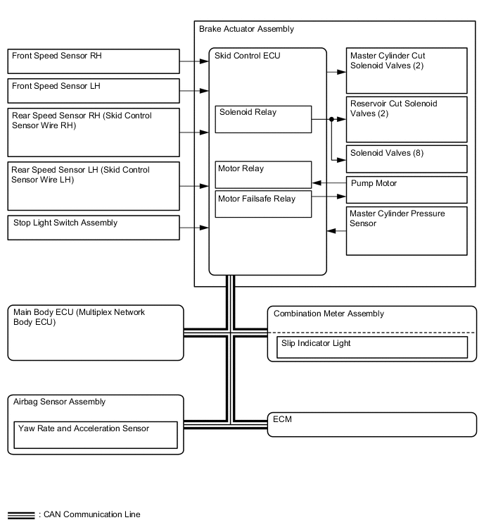
Figure 1. Example of Hill-start Assist Control when Climbing Uphill with Shift Lever in D (Driver Depresses Accelerator Pedal to Start Off after Hill-start Assist Control Operation)
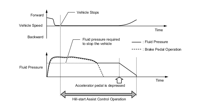
Figure 2. Example of Hill-start Assist Control when Climbing Uphill with Shift Lever in D (Driver Takes No Action after Hill-start Assist Control Operation)
Item Port Not Activated Activated Holding Mode Reduction Mode Master Cylinder Cut Solenoid Valve (1) (A) OFF (Open) ON* ← (4) (D) OFF (Open) ON* ← Reservoir Cut Solenoid Valve (2) (B) OFF (Closed) ← ← (3) (C) OFF (Closed) ← ← Front Brake Pressure Holding Solenoid Valve (5) (E) OFF (Open) ← ← (8) (H) OFF (Open) ← ← Pressure Reduction Solenoid Valve (9) (I) OFF (Closed) ← ← (12) (J) OFF (Closed) ← ← Brake Wheel Cylinder Pressure Right - - Hold Reduce Left - - Hold Reduce Rear Brake Pressure Holding Solenoid Valve (6) (F) OFF (Open) ← ← (7) (G) OFF (Open) ← ← Pressure Reduction Solenoid Valve (10) (J) OFF (Closed) ← ← (11) (K) OFF (Closed) ← ← Brake Wheel Cylinder Pressure Right - - Hold Reduce Left - - Hold Reduce Pump OFF OFF OFF Tech Tips
*: Hydraulic pressure is controlled by continuously cycling the solenoid valves between open and closed, according to the operating conditions.
-
-
Brake Control Operation (Pre-crash Safety System Operating)
-
If the PCC ECU determines that the possibility of a collision is high, the ECU sends the pre-crash brake assist request signal to the skid control ECU. Upon receiving the signal, the skid control ECU switches the brake assist to standby mode. When the driver depresses the brake pedal, the skid control ECU operates the brake assist based on the master cylinder pressure sensor.
-
If a collision is unavoidable, the skid control ECU actuates the motor in the brake actuator assembly to apply direct pressure to the wheel cylinders even if the driver does not press the brake pedal. This brake control operates in the same way as the normal brake operation.
-
-
-
FAIL-SAFE
-
In the event of a malfunction in the ABS, skid control ECU prohibits the brake control system.
-
In the event of a malfunction in the EBD, the brake system is operated as long as possible even if the ABS is prohibited. If the EBD control becomes impossible, the brake warning light illuminates to inform the driver of that. In this case, the brake system is operated in the same condition as the brake system without the brake control system.
-
In the event of a malfunction in the TRC and/or VSC, skid control ECU prohibits the TRC and VSC operation.
-
If a communication malfunction occurs between the skid control ECU and the steering angle sensor, yaw rate and acceleration sensor, or ECM, the skid control ECU stops the TRC and VSC.
-
When the ECM detects the Diagnostic Trouble Code (DTC), it will disable the TRC and VSC.
-
-
DIAGNOSIS
-
If the skid control ECU detects a malfunction in the brake control system (ABS with EBD), then the ABS warning light, brake warning light individually according to the function in which the malfunction has been detected, to alert the driver of the malfunction.
-
If the skid control ECU detects a malfunction in the brake control system (ABS with EBD, brake assist, TRC and VSC), then the ABS warning light, brake warning light, or slip indicator light illuminate either individually or as a group according to the function in which the malfunction has been detected, to alert the driver of the malfunction.
-
At the same time, the DTCs are stored in memory.
-
This system has a sensor signal check (test mode) function.
-
For details of the DTCs that are stored in skid control ECU memory and the DTCs that are output through the sensor signal check functions, see the Repair Manual.
-