MANUAL TRANSAXLE SYSTEM
-
FUNCTION
-
Gear Shift Indicator (except GRMN)
-
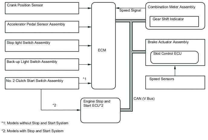
In the Gear Shift Indicator, the ECM calculates to determine a gear position for good environmental performance from vehicle conditions, and requests the combination meter assembly to indicate "upshifting/downshifting". Then, the Gear Shift Indicator in the combination meter assembly shows the driver to shift recommendation.
-
The ECM determines the actual gear position based on the signals from the speed sensor and crank position sensor, and the target gear position based on the signals from the accelerator pedal sensor assembly and speed sensor.
-
By driving in accordance with the shift change recommendations that are indicated by the Gear Shift Indicator, the driver can enhance environmental performance, improving fuel economy and reducing exhaust gas output within limits of engine performance.
Control of Gear Shift Indicator Control Outline System Start Checks the bulb of the indicator lights from the time the ignition switch is turned ON until the engine is started. Shifting Recommendation Control Calculates an environmentally favorable shift position based on the driving conditions of the vehicle, and gives shifting recommendation. Shift Control in Uphill Traveling Prevents unnecessary shifting instruction by estimating the gradient of the road based on the driving conditions. Provides shift position instructions that enable the vehicle to attain the proper drive force. Delta Throttle Accelerate Control Determines a deceleration request when the driver releases the accelerator pedal suddenly. Thus, it will not provide a shift-up instruction. However, it will provide a shift-up recommendation to protect the engine if the engine speed is high. -
The Gear Shift Indicator will not effect control while the vehicle is being driven in reverse.
-
The Gear Shift Indicator will not effect control while the vehicle is stopped or the clutch is not being engaged while shifting.
-
Upon receiving a shift instruction request from the ECM, the combination meter assembly will illuminate the indicator light.
-
The 2 indicator lights illuminate simultaneously during a bulb check.*
-
*: Models with monochrome type multi-information display
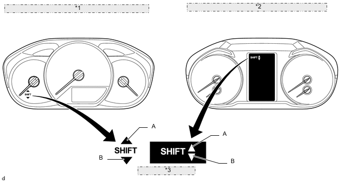
*1 Combination Meter Assembly (Monochrome Type Multi-information Display) *2 Combination Meter Assembly (Color Type Multi-information Display) *3 Gear Shift Indicator Illumination Location Instruction Description A Shift-up Recommendation B Shift-down Recommendation A and B Bulb Check* *: Models with monochrome type multi-information display
-
-
-
-
CONSTRUCTION
-
Transmission Gear
-
Fuel economy has been improved without sacrificing performance by further lowering the gear ratios of the 6th gear to extend the gear ratio range.
-
The newest method of tooth profile analysis is used for the gears to optimize the tooth profile, which results in a noise reduction.
-
Shot peening has been performed on the surfaces of the 3rd and 4th gears to ensure the strength and durability of the gears. (for GRMN)
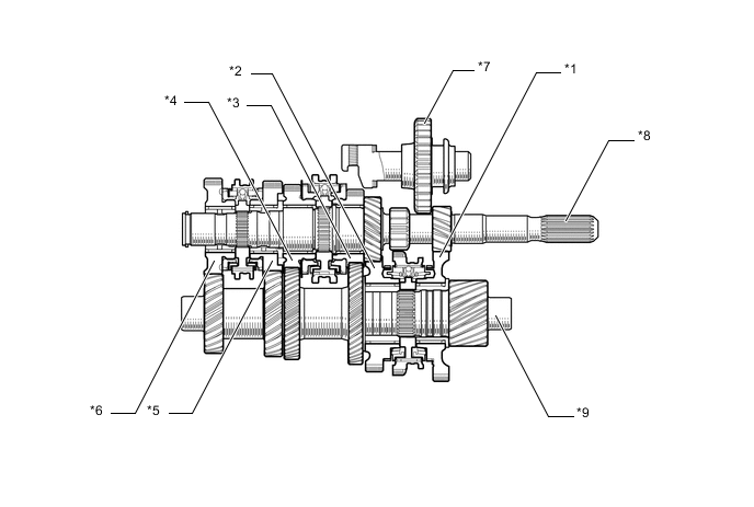
Text in Illustration *1 1st Gear *2 2nd Gear *3 3rd Gear *4 4th Gear *5 5th Gear *6 6th Gear *7 Reverse Idler Gear *8 Input Shaft *9 Output Shaft - -
-
-
Synchromesh Mechanism
-
The transmission synchromesh mechanism consists of a transmission hub sleeve, synchronizer ring, transmission clutch hub and synchromesh shifting key.
-
For the transmission hub sleeve for all gears, the spline chamfer angle has been made narrower and the spline tooth thickness has been made thinner. This reduces the engagement force and the distance over which a push-through force is generated during shift changes and gives a smooth shift feeling.
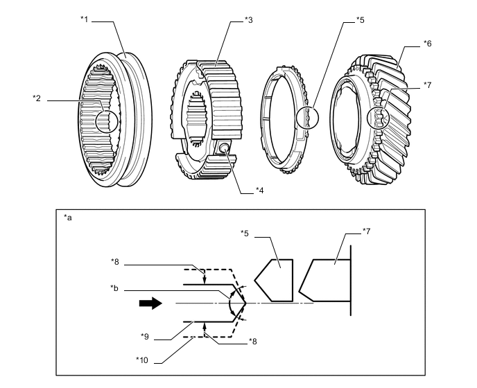
Text in Illustration *1 Transmission Hub Sleeve *2 Sleeve Spline *3 Transmission Clutch Hub *4 Synchromesh Shifting Key *5 Synchronizer Ring *6 Gear *7 Gear Piece *8 Thinner Spline Tooth *9 Sleeve Spline for EC62 *10 Commonly-used Sleeve Spline *a Image of Spline Tooth During Shift Change *b Chamfer Angle 
Shift - - -
A 2 step chamfer structure is used for the No. 2 transmission hub sleeve for the 3rd and 4th gears.
-
In the 2 step chamfer structure, synchronizing teeth and engaging teeth are provided in the spline of the No. 2 transmission hub sleeve, which allows the engaging teeth to be located closer to the gear piece than the synchronizing teeth during synchronization action. This shortens the distance that the sleeve has to move after the synchronization has been completed until the engagement with the gear piece begins, and reduces shocks that are generated when the synchronization with the gear piece is lost.
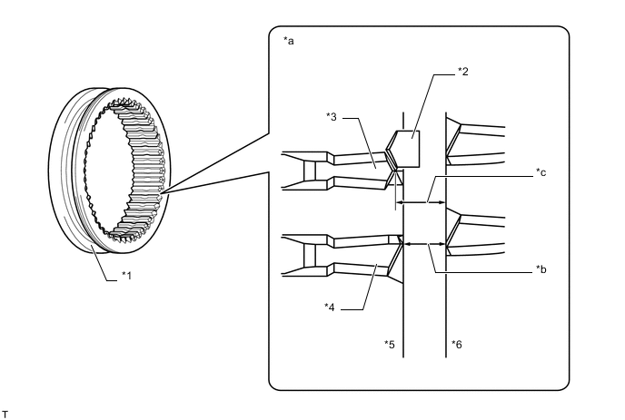
Text in Illustration *1 No. 2 Transmission Hub Sleeve *2 Synchronizer Ring *3 Synchronizing Teeth *4 Engaging Teeth *5 Spline of No. 2 Transmission Hub Sleeve *6 Spline of Gear Piece for 3rd or 4th Gear *a Sleeve and Gear Piece Spline Status in Synchronization Action *b Distance of EC62 Synchronizing System *c Distance of previous Synchronizing System - - -
The ball and spring in the synchromesh shifting key have been combined into one unit, thus ensuring the stable position of the synchromesh shifting and improving shift feeling.
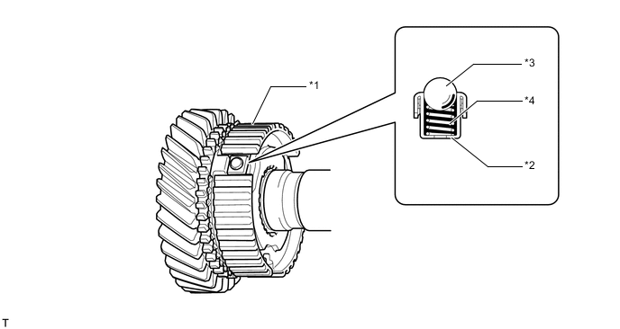
Text in Illustration *1 Transmission Clutch Hub *2 Synchromesh Shifting Key *3 Ball *4 Spring
-
-
Shift Mechanism
-
EC62 manual transaxle adopts a remote-controlled shift mechanism to reduce shift knob vibration.
-
The shift mechanism consists of a shift outer lever, a select outer lever, a shift and select lever shaft, 3 shift forks, a reverse shift arm bracket assembly and a reverse shift fork.
-
The distances between the shift and select lever shaft and each shift fork shaft (see B in the illustration below), and the distance between the shift fork and the shift fork shaft (see C in the illustration below) have been shortened. This reduces sliding resistance, thereby improving shift feeling.
-
The shape of the shift fork has been made symmetrical to improve shift feeling.
-
The select mechanism is separated from the shift mechanism in which a mass damper is installed, thus improving the select feeling.
-
A plastic pad is attached to the contact surface between the shift fork and the transmission hub sleeve to reduce the sliding resistance.
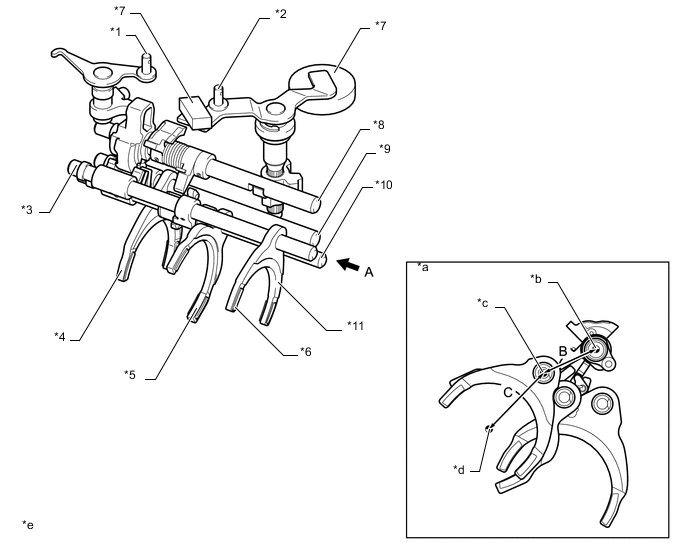
*1 Outer Select Lever *2 Outer No. 1 Shift Lever *3 No. 3 Shift Fork Shaft *4 No. 1 Shift Fork *5 No. 2 Shift Fork *6 Pad *7 Shift Lever Damper *8 Shift and Select Lever Shaft *9 No. 1 Shift Fork Shaft *10 No. 2 Shift Fork Shaft *11 No. 3 Shift Fork - - *a View from A *b Center of Shift and Select Lever Shaft *c Center of Shift Fork Shaft *d Center of Input Shaft *e The illustrations shown are examples only. - - Shift Fork Shaft and Shift Fork Operation Gear 1st and 2nd 3rd and 4th 5th and 6th Reverse Shift Fork Shaft No. 1 No. 2 No. 3 No. 4 Shift Fork No. 1 No. 2 No. 3 Reverse
-
-
Oil Separator
-
The oil separator is fitted around the output shaft gear to prevent the gear from directly stirring up the oil in the sump. This reduces the agitation resistance, increases the torque transmission efficiency and improves fuel economy.
-
The oil separator is fitted on the side of the front differential ring gear so that the tank construction is provided and oil that has been used for lubrication is stored temporarily between the oil separator and the manual transmission case. Therefore, only the amount of oil required for lubrication can be separated and the amount of oil that has to be agitated is reduced. This reduces the agitation resistance, increases the torque transmission efficiency and improves fuel economy.
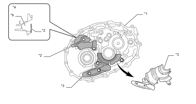
Text in Illustration *1 Manual Transmission Case *2 Transmission Oil (MTM) Separator *3 Manual Transmission Oil Separator Sub-assembly - - *a Cross Section *b Tank Construction
-
-
Bearing
-
Low-friction bearings are used for the front output shaft bearing, rear output shaft bearing, front differential case front tapered roller bearing and front differential case rear tapered roller bearing to improve the torque transmission efficiency, which results in an improvement in fuel economy.
-
Special heat treatment has been conducted for the rear input shaft radial ball bearing to ensure durability under severe conditions of use such as sports driving. (for GRMN)
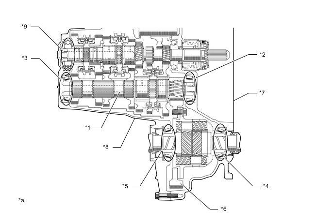
*1 Output Shaft *2 Front Output Shaft Bearing *3 Rear Output Shaft Bearing *4 Front Differential Case Front Tapered Roller Bearing *5 Front Differential Case Rear Tapered Roller Bearing *6 Front Differential Ring Gear *7 Transaxle Case *8 Manual Transmission Case *9 Rear input shaft radial ball bearing - - *a The illustrations shown are examples only. - -
-
-
Differential (except GRMN)
-
The pre-load differential gear, in which the conical spring is located between the side gear and the slide gear washer, is used on some models.
-
The load of the conical spring applies a friction force to the sliding area, enhancing straightline stability and steering stability.
-
Under light load and low differential rotation speeds, due to the friction force of the sliding area, the differential limit torque for the left and right wheels is achieved within the range of the conical spring allowable load. At middle and high load ranges, which are beyond the allowable load of the conical spring, the system performs as an open differential.
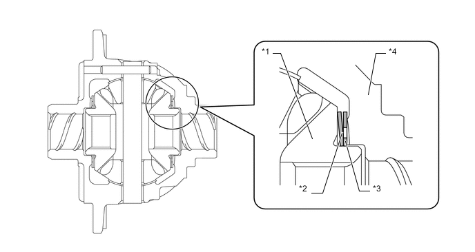
Text in Illustration *1 Side Gear *2 Conical Spring *3 Slide Gear Washer *4 Differential Case
-
-
Differential (for GRMN)
-
The torque-sensitive limited slip differential (Torsen LSD) consists of a differential case, 8 planet gears, 2 side gears and 3 thrust washers. Planet gears mesh with one another as a pair, and each gear of the pair meshes with the side gear on its right or left side. The planet gears are supported by the hole that is provided in the differential case. They are constructed so that they rotate while revolving over the side gear.
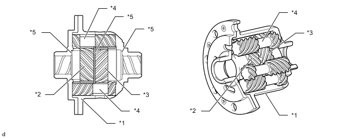
*1 Differential Case *2 Left Side Gear *3 Right Side Gear *4 Planet Gears *5 Thrust Washers - -
-
-
Shift Control Mechanism
-
A pull collar type shift lever assembly, which is equipped with an inhibit mechanism, is used.
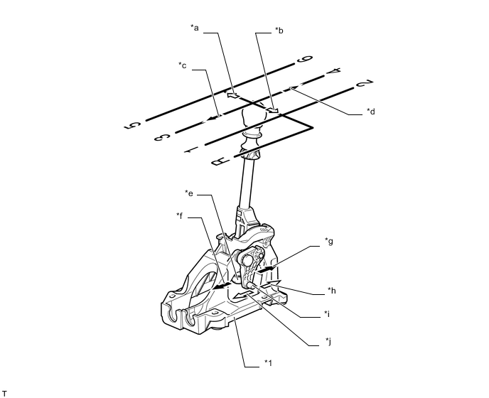
Text in Illustration *1 Floor Shift Lever Assembly - - *a Selecting High Gears *b Selecting Low Gears *c Shifting to 1st, 3rd, 5th and Reverse *d Shifting to 2nd, 4th and 6th *e Shift Cable Connecting Portion *f Shifting Direction to 2nd, 4th and 6th Gears *g Shifting Direction to 1st, 3rd, 5th and Reverse Gears *h High Gear Selecting Direction *i Select Cable Connecting Portion *j Low Gear Selecting Direction
-
-
-
OPERATION
-
Pre-synchronizing System
-
A pre-synchronizing system is used. While reverse is selected, the synchromesh mechanism of the 6th gear is activated, thereby preventing gear clash feeling when shifting into reverse gear.
-
When the shift lever is moved toward the reverse position, the No. 1 reverse pre-balk head fitted to the shift and select lever shaft turns (See A in the illustration below).
-
Then the No. 1 reverse pre-balk head engages with the No. 2 reverse pre-balk head, and the No. 2 reverse pre-balk head turns (See B in the illustration below).
-
As the protrusion of the No. 2 reverse pre-balk head moves upward, it pushes the No. 3 reverse pre-balk head to the left in the illustration below (See C in the illustration below).
-
As a result, the No. 3 shift fork shaft moves to the left (see D in the illustration below) so that the synchromesh mechanism of the 6th gear is activated and suppresses the rotation of the input shaft.
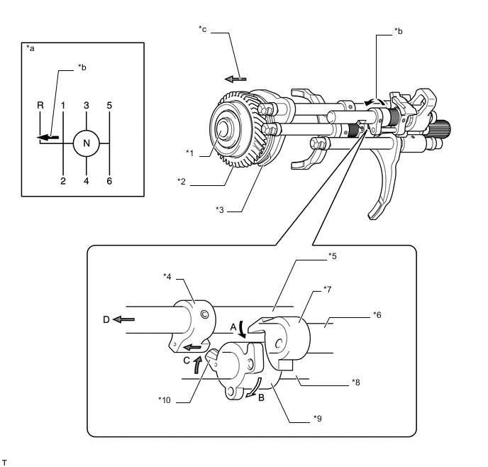
Text in Illustration *1 Input Shaft *2 6th Gear *3 No. 3 Shift Fork *4 No. 3 Reverse Pre-balk Head *5 No. 3 Shift Fork Shaft *6 Shift and Select Lever Shaft *7 No. 1 Reverse Pre-balk Head *8 No. 2 Shift Fork Shaft *9 No. 2 Reverse Pre-balk Head *10 Protrusion *a Shift Pattern *b Reverse Direction Selected *c Synchromesh Mechanism of 6th Gear Activated - -
-
-
Inhibit Mechanism
-
A stopper cover is provided at the 1st-2nd side, so that the pull collar must be pulled upward in order to shift into reverse. This reduces the amount of shift effort and ensures a precise shifting operation.
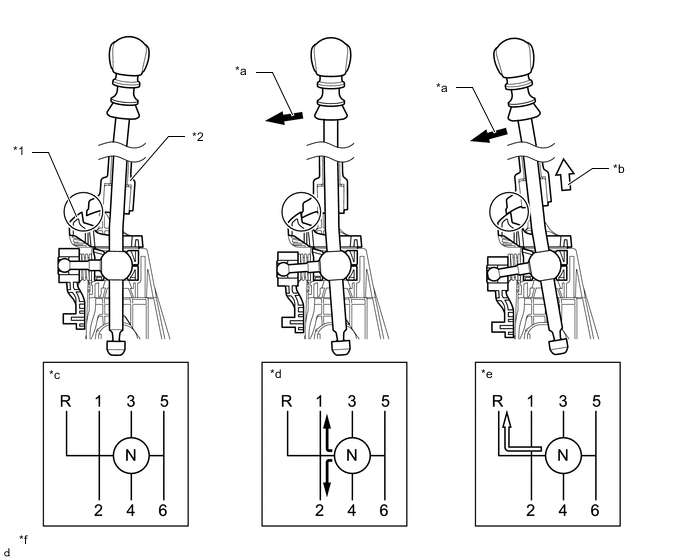
*1 Stopper Cover *2 Pull Collar *a Select Direction *b Pulled Up *c Neutral Position *d 1st/2nd Position *e Reverse Position *f The illustrations shown are examples only.
-
-
Torque-sensitive Limited Slip Differential (Torsen LSD)
-
Straight-Ahead Operation
-
As the right and left drive shafts rotate in the same direction at the same cycle, the side gears and planet gears rotate together with the differential case as a unit, thus the driving force is transmitted in the sequence shown below.
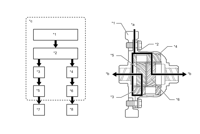
*1 Ring Gear *2 Differential Case *3 Left Planet Gear *4 Right Planet Gear *5 Left Side Gear *6 Right Side Gear *7 Left Drive Shaft *8 Right Drive Shaft *a Input 100% *b Output 50% *c Rotate together as a unit - -
-
-
Cornering
-
Supposing that the differential case is not moving, rotating the left side gear counterclockwise causes planet gear A (which meshes with the left side gear) to rotate clockwise. Furthermore, planet gear B, which is paired with planet gear A rotates counterclockwise, causing the right side gear (which meshes with planet gear B) to rotate clockwise. Therefore the left and right side gears rotate in the opposite direction to each other, accomplishing a motion differential.
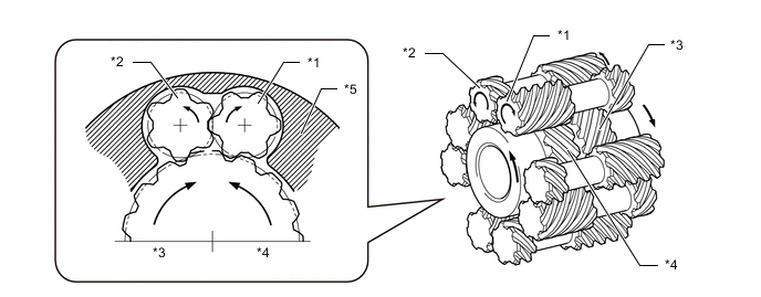
*1 Planet Gear A *2 Planet Gear B *3 Right Side Gear *4 Left Side Gear *5 Differential Case - -
-
-
Limited Slip Differential Operation
-
Limited slip differential operation is accomplished primarily by the friction that is generated at 2 locations, which are between the planet gear's teeth tips and differential case's inner wall, and between the side gear end face and thrust washer. The resultant force F1, which is created in proportion to the input torque by the meshing reaction of the planet gear and the side gear (reaction force f1) and the meshing reaction of the planet gears themselves (reaction force f2), acts in the direction to push the planet gears toward the differential case. Thus, friction force μF1, which is generated between the teeth tips of the planet gear and the inner wall of the differential case, acts in the direction to stop the planet gear's rotation. At the same time, due to the helical angle that is provided in the differential gear, thrust force F2 is generated toward the axle shaft. Thus, friction force μF2 will act between the side gear end face and thrust washer in the direction to stop the side gear rotation. (When decelerating, thrust force F2' is generated.)
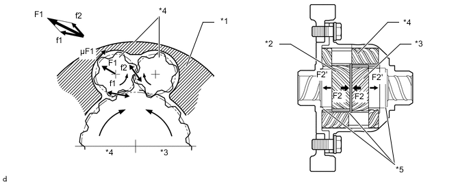
*1 Differential Case *2 Left Side Gear *3 Right Side Gear *4 Planet Gears *5 Thrust Washers - -
Note
-
Never apply driving force with only one front wheel in contact with ground, and never spin only one wheel to perform operations such as on-the-car wheel balancing. Due to the structure of the Torsen LSD, in such cases, the driving force is also transmitted to the stopped wheel, and it may cause the vehicle to lurch forward. It also exerts stress on the differential mechanism and may result in damage.
-
The type and size of front wheels and tires shall be the same on both sides, and reduction in tire diameter due to wear shall not largely differ between the right and left.
-
-
-