MANUAL TRANSAXLE SYSTEM
-
FUNCTION
-
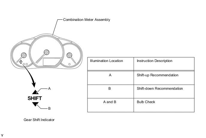
Gear Shift Indicator
-
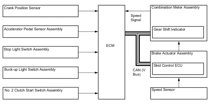
In the Gear Shift Indicator, the ECM calculates to determine a gear position for good environmental performance from vehicle conditions, and requests the combination meter assembly to indicate "upshifting/downshifting". Then, the Gear Shift Indicator in the combination meter assembly shows the driver to shift recommendation.
-
The ECM determines the actual gear position based on the signals from the speed sensor and crank position sensor, and the target gear position based on the signals from the accelerator pedal sensor assembly and speed sensor.
-
By driving in accordance with the shift change recommendations that are indicated by the Gear Shift Indicator, the driver can enhance environmental performance, improving fuel economy and reducing exhaust gas output with in limits of engine performance.
Control of Gear Shift Indicator Control Outline System Start Checks the bulb of the indicator lights from the time the ignition switch is turned ON until the engine is started. Shifting Recommendation Control Calculates an environmentally favorable shift position based on the driving conditions of the vehicle, and gives shifting recommendation. Shift Control in Uphill Traveling Prevents unnecessary shifting instruction by estimating the gradient of the road based on the driving conditions. Provides shift position instructions that enable the vehicle to attain the proper drive force. Delta Throttle Accelerate Control Determines a deceleration request when the driver releases the accelerator pedal suddenly. Thus, it will not provide a shift-up instruction. However, it will provide a shift-up recommendation to protect the engine if the engine speed is high. -
The Gear Shift Indicator will not effect control while the vehicle is being driven in reverse.
-
The Gear Shift Indicator will not effect control while the vehicle is stopped or the clutch is not being engaged while shifting.
-
Upon receiving a shift instruction request from the ECM, the combination meter assembly will illuminate the indicator light.
-
The 2 indicator lights illuminate simultaneously during a bulb check.
-
-
-
CONSTRUCTION
-
Shift and Select Mechanism
-
An excellent shift feel has been achieved through the use of the shift lever damper on the shift and select lever shaft assembly.
-
A inner No. 1 shift lever is provided on the shift and select lever shaft assembly. The movement distance of the shift and select lever shaft assembly in the select direction after completing the shifting is regulated by the inner No. 1 shift lever and shift gate pin. This clarifies the position of the shift knob and enables accurate shift operations.
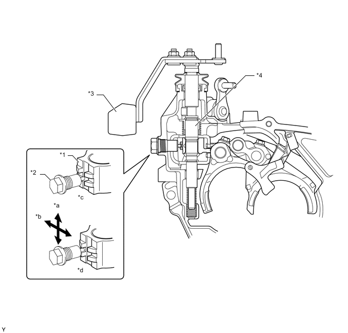
Text in Illustration *1 Inner No. 1 Shift Lever *2 Shift Gate Pin *3 Shift Lever Damper *4 Shift and Select Lever Shaft Assembly *a Select Direction *b Shift Direction *c Neutral Position *d Shift Completed
-
-
Shift Control Mechanism
-
A transmission control cable assembly with a length adjustment mechanism is used.
-
The shift lever on the TMMF made models is a 2 structure type, with a socket installed on the over injection ball, and a bush is provided for the small select sphere. As a result, an excellent shift feeling is realized.
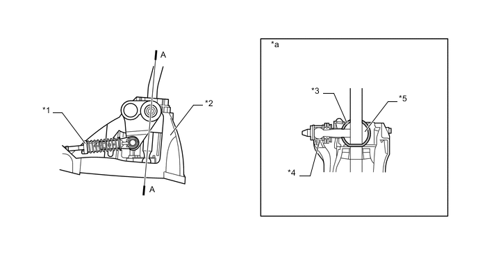
Text in Illustration *1 Transmission Control Cable Assembly *2 Floor Shift Shift Lever Assembly *3 Socket *4 Bush *5 Over Injection Ball - - *a A-A Cross Section - -
-
-