STOP AND START
-
FUNCTION OF MAIN COMPONENTS
Component Function Engine Stop and Start ECU
-
Backup Boost Converter
-
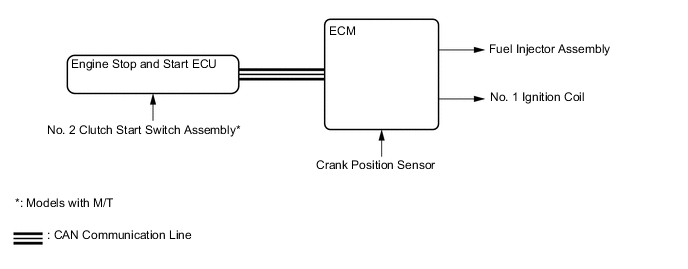
Sends either an engine stop or restart signal to the ECM according to the signals from each sensor and switch.
-
Supplies battery voltage to help make up for the voltage drop that occurs when the engine is restarted, preventing the operation of various systems from being interrupted due to low battery voltage.
-
Supplies battery voltage to the oil pump motor assembly.*1
Starter Assembly Starts the engine. Generator Assembly Transmits the power generating conditions to the power management control ECU*2 or ECM*3. Oil Pump Motor Assembly*1 Holds the CVT oil pressure while idle stop. This integrates the oil pump motor driver. No. 2 Clutch Start Switch Assembly*4 Recognizes that the clutch pedal is not depressed and sends a signal to the engine stop and start ECU. Clutch Start Switch Assembly*4 Recognizes that the clutch pedal is depressed and sends a signal to the engine stop and start ECU. Neutral Position Switch*4 Recognizes that the shift lever is in N and sends a signal to the engine stop and start ECU. Park/neutral Position Switch Assembly*1 Recognizes that the shift lever position and sends a signal to the engine stop and start ECU. Stop Light Switch Assembly Detects that the brake pedal is in a released condition, and transmits this information via the ECM to the stop and start ECU. Brake Vacuum Pressure Sensor Detects the brake booster vacuum pressure and sends a signal to the engine stop and start ECU*2 or ECM*3. Engine Hood Courtesy Switch Detects whether the hood is open or closed and sends a signal to the engine stop and start ECU. Front Door Courtesy Light Switch (Driver) Detects whether the door is open or closed and sends a signal to the engine stop and start ECU via the main body ECU (multiplex network body ECU) via CAN communication. Front Seat Belt Buckle Switch (Driver) Detects whether or not the driver's seat belt has been fastened, and sends a signal to the engine stop and start ECU via the main body ECU (multiplex network body ECU) via CAN communication.*1 Stop and Start System Cancel Switch Assembly (Warning Canceling Switch Assembly) The operation of the system can be cancelled by pressing the stop and start system cancel switch assembly (warning canceling switch assembly). Pressing the switch again or turning the power source off and back on restores the operation of the system. Battery Current Sensor Assembly*2 Detected the battery charging and discharging amount and sends a signal to the power management control ECU. Battery State Sensor Assembly*3 Detected the battery charging and discharging amount and sends a signal to the ECM. Crank Position Sensor Detects the crank angle when the engine stops and transmits that information to the ECM. Ambient Temperature Sensor (Thermistor Assembly) Detects ambient temperature and outputs it to the combination meter assembly. Steering Angle Sensor Detects the steering direction and angle of the steering wheel. Air Conditioning Amplifier Assembly Sends an outside temperature signal and A/C switch signal to the engine stop and start ECU. Combination Meter Assembly Stop and Start Indicator Light When the engine is stopped due to stop and start system control, if the driver door is opened, the buzzer sounds and the stop and start indicator light illuminates to inform the driver that the engine was stopped due to stop and start system control. (Engine restarts) Stop and Start Cancel Indicator Light
-
Turns on to inform the driver that the system has been disabled when stop and start system operation is prohibited by stop and start system cancel switch assembly (warning canceling switch assembly).
-
If a system malfunction is detected, the stop and start cancel indicator light blinks to inform the driver.
Multi-information Display Displays idling stop time, etc. (Refer to "OPERATION" page.) ECM Sends various information about engine conditions to the engine stop and start ECU. Skid Control ECU
-
Sends a vehicle speed signal to the engine stop and start ECU.
-
Transmits the brake fluid pressure signal to the engine stop and start ECU.
-
Maintains the brake fluid pressure from the time the brake pedal is released until driving force is generated when the engine is stopped due to stop and start system control.
Airbag Sensor Assembly Sends airbag deployment information in the event of a collision and deceleration signal to the engine stop and start ECU. Power Management Control ECU*2 Transmits the battery current sensor assembly signal to the engine stop and start ECU. Radio and Display Receiver Assembly*5 Power will be supplied from the engine stop and start ECU during idle stop or when restarting the engine. ST Relay, ST No. 2 Relay*1 Operates the starter assembly by the on signals from the engine stop and start ECU. *1: Models with CVT
*2: Models with 1KR-FE and 1ND-TV engine
*3: Models with 2NR-FKE engine
*4: Models with M/T
*5: Models with radio and display receiver assembly
-
-
OPERATING CONDITION
-
Operating conditions at engine stop and restart
-
The engine may stop if all of these conditions are detected.
Tech Tips
-
At battery temperatures of -15°C (5°F) or below, or 75°C (167°F) or above, stop and start system control is prohibited. When stop and start system control is prohibited, after the battery temperature returns to -10°C (14°F) or higher, and 70°C (158°F) or lower, stop and start system control will be permitted.
-
In the stop and start system, the engine stop and start ECU switches the system control mode (stop and start system control permitted/prohibited) based on the battery condition (charge/discharge condition) to protect the battery and to ensure stable engine restarting performance. The battery charge-discharge condition is determined from the integrated current value calculated from the battery sensor signal. The integrated current value is obtained by multiplying the current (ampere) detected from the battery sensor by the time (seconds), and it is expressed in the unit A-sec. This can be measured by the Global TechStream (GTS). The engine stop and start ECU determines the power charge based on the integrated current value, and it prohibits stop and start system control if the value is below the threshold, because the battery might not be able to start the engine. The threshold values according to the battery temperature and battery charge condition.
Models with 1KR-FE Engine Item Operating Condition Engine Stop Engine Coolant Temperature 40°C to 105°C (104°F to 221°F) Outside Temperature Higher than -5°C (23°F) Driver Door After closed, 3 seconds elapsed. Brake Booster Vacuum Sufficient brake booster vacuum Stop and Start System Cancel Switch Assembly (Warning Canceling Switch Assembly) OFF (Not a system control stopped state) Vehicle Speed
-
0 km/h (0 mph)
-
Vehicle has been driven at 7 km/h (4.4 mph) or more (first operation of control only, second operation of control is 2 km/h (1.2 mph) or more).
Engine Speed Below 1200 rpm Clutch Pedal Released Shift Lever Position Neutral Driver's Seat Belt After the driver's seat belt fastening, after 3 seconds. Engine Hood After closed, 3 seconds elapsed. Battery Voltage 8.8 V or more at engine start. Battery Temperature -10°C to 70°C (14°F to 158°F)*1 Battery Integrated Current*2 When the integrated current value meets any of the following conditions:
-
-3974 A-sec or more: "Status of Battery Charge Control" is Charge Control Coordination Mode or Low Temperature Mode.*3
-
0 A-sec or more: "Status of Battery Charge Control" is Stop and Start Standalone Mode, Start Restriction Mode or Temperature High/Low Mode.*4
Air Conditioning Except when air conditioner is cooling down, heater is warming up, or defogger control is active. ECM Learning Completed Tech Tips
*1: When the battery temperature becomes -15°C (5°F) or lower or 75°C (167°F) or higher, control is prohibited. After control is prohibited and the battery temperature rises to -10°C (14°F) or higher or falls to 70°C (158°F) or lower, control is performed.
*2: In the stop and start system, the engine stop and start ECU switches the system control mode (stop and start system control permitted/prohibited) based on the battery condition (charge/discharge condition) to protect the battery and to ensure stable engine restarting performance. The battery charge-discharge condition is determined from the integrated current value calculated from the battery sensor signal. The integrated current value is obtained by multiplying the current (ampere) detected by the battery sensor by the time (seconds), and is expressed in the unit A-sec. This can be measured by the Global TechStream (GTS). The engine stop and start ECU determines the power charge based on the integrated current value and prohibits stop and start system control if the value is below the threshold, because the battery might not be able to start the engine. The threshold varies according to the battery temperature and battery charge condition.
*3: After the integrated current value becomes -4838 A-sec or less, in order to charge the battery, control is prohibited until the value becomes -3974 A-sec or more.
*4: After the integrated current value becomes -864 A-sec or less, in order to charge the battery, control is prohibited until the value becomes 0 A-sec or more.
Models with 2NR-FKE Engine Item Operating Condition Engine Stop Engine Coolant Temperature 39°C to 105°C (102°F to 221°F) Outside Temperature Higher than -5°C (23°F) Road Grade -8° to 8° CVT Oil Temperature*1 25°C to 110°C (77°F to 230°F) Driver Door After closed, 3 seconds elapsed. Brake Booster Vacuum Sufficient brake booster vacuum Stop and Start System Cancel Switch Assembly (Warning Canceling Switch Assembly) OFF (Not a system control stopped state) Vehicle Speed
-
0 km/h (0 mph)
-
Vehicle has been driven at 7 km/h (4.4 mph) or more (first operation of control only, second operation of control is 2 km/h (1.2 mph) or more).
Engine Speed Below 1200 rpm Clutch Pedal*2 Released Shift Lever Position
-
Other than R position*1
-
Neutral*2
Driver's Seat Belt After the driver's seat belt fastening, after 3 seconds. Engine Hood After closed, 3 seconds elapsed. Battery Voltage*3
-
7.6 V or more at engine start.*1
-
6.5 V or more at engine start.*2
Battery Temperature -10°C to 70°C (14°F to 158°F)*4 Battery Integrated Current*5 (Models with LN3-ISS Type Battery) When the integrated current value meets any of the following conditions:
-
-4554 A-sec or more: "Status of Battery Charge Control" is Charge Control Coordination Mode, Stop and Start Standalone Mode or Low Temperature Mode.*6
-
0 A-sec or more: "Status of Battery Charge Control" is Start Restriction Mode or Temperature High/Low Mode.*7
Battery Integrated Current*5 (Models with LN2-ISS Type Battery) When the integrated current value meets any of the following conditions:
-
-3974 A-sec or more: "Status of Battery Charge Control" is Charge Control Coordination Mode, Stop and Start Standalone Mode or Low Temperature Mode.*8
-
0 A-sec or more: "Status of Battery Charge Control" is Start Restriction Mode or Temperature High/Low Mode.*9
Air Conditioning Except when air conditioner is cooling down, heater is warming up, or defogger control is active. ECM Learning Completed
-
*1: Models with CVT
-
*2: Models with M/T
Tech Tips
*3: If an unspecified battery is used, the value of Min Voltage supplied from the battery to the starter will be different than when an appropriate battery is used.
*4: When the battery temperature becomes -15°C (5°F) or lower or 75°C (167°F) or higher, control is prohibited. After control is prohibited and the battery temperature rises to -10°C (14°F) or higher or falls to 70°C (158°F) or lower, control is performed.
*5: In the stop and start system, the engine stop and start ECU switches the system control mode (stop and start system control permitted/prohibited) based on the battery condition (charge/discharge condition) to protect the battery and to ensure stable engine restarting performance. The battery charge-discharge condition is determined from the integrated current value calculated from the battery sensor signal. The integrated current value is obtained by multiplying the current (ampere) detected by the battery sensor by the time (seconds), and is expressed in the unit A-sec. This can be measured by the Global TechStream (GTS). The engine stop and start ECU determines the power charge based on the integrated current value and prohibits stop and start system control if the value is below the threshold, because the battery might not be able to start the engine. The threshold varies according to the battery temperature and battery charge condition.
*6: After the integrated current value becomes -5544 A-sec or less, in order to charge the battery, control is prohibited until the value becomes -4554 A-sec or more.
*7: After the integrated current value becomes -990 A-sec or less, in order to charge the battery, control is prohibited until the value becomes 0 A-sec or more.
*8: After the integrated current value becomes -4838 A-sec or less, in order to charge the battery, control is prohibited until the value becomes -3974 A-sec or more.
*9: After the integrated current value becomes -864 A-sec or less, in order to charge the battery, control is prohibited until the value becomes 0 A-sec or more.
Models with 1ND-TV Engine Item Operating Condition Engine Stop Engine Coolant Temperature A predetermined temperature*1 to 105°C (221°F) Outside Temperature Higher than -5°C (23°F) Driver Door After closed, 3 seconds elapsed. Brake Booster Vacuum Sufficient brake booster vacuum Stop and Start System Cancel Switch Assembly (Warning Canceling Switch Assembly) OFF (Not a system control stopped state) Vehicle Speed
-
0 km/h (0 mph)
-
Vehicle has been driven at 7 km/h (4.4 mph) or more (first operation of control only, second operation of control is 2 km/h (1.2 mph) or more).
Engine Speed Below 1200 rpm Clutch Pedal Released Shift Lever Position Neutral Driver's Seat Belt After the driver's seat belt fastening, after 3 seconds. Engine Hood After closed, 3 seconds elapsed. Battery Voltage 6.5 V or more at engine start. Battery Temperature -10°C to 70°C (14°F to 158°F)*2 Battery Integrated Current*3 When the integrated current value meets any of the following conditions:
-
-4554 A-sec or more: "Status of Battery Charge Control" is Charge Control Coordination Mode or Low Temperature Mode.*4
-
0 A-sec or more: "Status of Battery Charge Control" is Stop and Start Standalone Mode, Start Restriction Mode or Temperature High/Low Mode.*5
Air Conditioning Except when air conditioner is cooling down, heater is warming up, or defogger control is active. ECM Learning Completed Tech Tips
*1: The lowest operating temperature is determined by environmental conditions.
*2: When the battery temperature becomes -15°C (5°F) or lower or 75°C (167°F) or higher, control is prohibited. After control is prohibited and the battery temperature rises to -10°C (14°F) or higher or falls to 70°C (158°F) or lower, control is performed.
*3: In the stop and start system, the engine stop and start ECU switches the system control mode (stop and start system control permitted/prohibited) based on the battery condition (charge/discharge condition) to protect the battery and to ensure stable engine restarting performance. The battery charge-discharge condition is determined from the integrated current value calculated from the battery sensor signal. The integrated current value is obtained by multiplying the current (ampere) detected by the battery sensor by the time (seconds), and is expressed in the unit A-sec. This can be measured by the Global TechStream (GTS). The engine stop and start ECU determines the power charge based on the integrated current value and prohibits stop and start system control if the value is below the threshold, because the battery might not be able to start the engine. The threshold varies according to the battery temperature and battery charge condition.
*4: After the integrated current value becomes -5544 A-sec or less, in order to charge the battery, control is prohibited until the value becomes -4554 A-sec or more.
*5: After the integrated current value becomes -990 A-sec or less, in order to charge the battery, control is prohibited until the value becomes 0 A-sec or more.
-
-
The engine will restart if any of these conditions are detected.
Models with M/T Item Operating Condition Engine Restart Brake Insufficient brake booster vacuum. Air Conditioning / Heater
-
The timer in the air conditioning amplifier assembly operates when the air conditioning is on.
-
The A/C switch or blower switch is turned on manually while the engine is stopped.
-
When control is changed from stop and start system priority condition to normal condition.
Heater Switch Assembly*1 The heater switch is turned on. Stop and Start System Cancel Switch Assembly (Warning Canceling Switch Assembly) The stop and start system cancel switch (warning canceling switch assembly) is turned on. Battery
-
The battery voltage is less than 11.4 V.
-
The battery integrated current drops to below the threshold value.
Vehicle Speed Vehicle speed signal is input (such as a slope) Clutch Pedal Depressed. Driver's Door Opened. Driver's Seat Belt The driver's seat belt is unfastened. DPF Warning Indicator Light*2 Illuminates. *1: Models with combustion type power heater system
*2: Models with 1ND-TV engine
Models with CVT Item Operating Condition Engine Restart Brake
-
Insufficient brake booster vacuum.
-
Brake control system malfunction.
Air Conditioning / Heater
-
The timer in the air conditioning amplifier assembly operates when the air conditioning is on.
-
The A/C switch or blower switch is turned on manually while the engine is stopped.
-
When control is changed from stop and start system priority condition to normal condition.
Stop and Start System Cancel Switch Assembly (Warning Canceling Switch Assembly) The stop and start system cancel switch (warning canceling switch assembly) is turned on. Battery
-
The battery voltage is less than 11.4 V.
-
The battery integrated current drops to below the threshold value.
Engine Hood The engine hood is opened while the shift lever is in P or N. Vehicle Speed Vehicle speed signal is input (such as a slope) Brake Pedal Brake pedal released. Accelerator Pedal Depressed. Shift Lever
-
Moved to R position.
-
Moved from P or N position to another position.
Driver's Door Opened. Driver's Seat Belt The driver's seat belt is unfastened. -
-
-
-
SYSTEM CONTROL
-
Early Stage Injection Control (Models with 1KR-FE and 2NR-FKE Engine)
-
Early stage injection control shortens the time it takes the engine to restart after the stop and start system stops the engine, thus allowing smooth initial acceleration.
-
The ECM memorizes the crankshaft angle detected by the crank position sensor when the engine is stopped by the stop and start system.
-
The ECM judges the injection required and decides which cylinder to ignite when the driver does restart operation. The ECM then uses this information as it starts the engine.
-
-
Hill-start Assist Function (Models with CVT)
-
The driving force (creep phenomenon) of a former CVT vehicle is regulated by depressing the brake pedal while stopping, and the driving force is transmitted by releasing the brake pedal when starting the vehicle. However, when starting a stop and start system equipped vehicle with its engine stopped due to the activation of the idle stop function, there is a short time delay of the driving force to be generated as the engine will start after the brake pedal is released.
-
The hill-start assist function is a system to assist starting of a stop and start system equipped vehicle on a slope to deal with the reason described above, retaining the brake hydraulic pressure until the driving force is generated, and releasing the brake hydraulic pressure automatically after the driving force is generated.
-
-
Tandem Solenoid Starter Control (Models with CVT)
-
Tandem solenoid starter assembly equips with a pinion push out solenoid (SL1) and a motor drive solenoid (SL2) separately so that the pinion gear can engage with the ring gear even if the engine is rotating by its inertia before fully stopping.
-
If there is an engine start request while the engine is rotating by its inertia before fully stopping, the engine stop and start ECU drives the pinion push out solenoid (SL1) by determining the timing to push out the pinion gear to engage with the ring gear in accordance with the state of reduction of the engine rotation. After the pinion gear and the ring gear engages and a certain period of time passes, the motor drive solenoid (SL2) is driven to crank the engine.
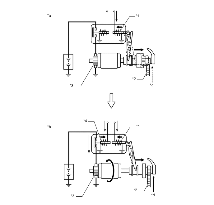
*1 Pinion Push Out Solenoid (SL1) *2 Ring Gear *3 Starter Motor *4 Motor Drive Solenoid (SL2) *a Operation of Pinion Gear *b Operation of Starter Motor *c Rotating Engine *d Cranking
-
-
System Prohibit Control
-
For safety, battery protection, comfort and ECM learning reasons, the engine stop and start ECU prohibits stop and start system operation if any one of the following conditions is met.
Prohibition Reason Condition Safety If the engine is started with the hood open, such as when jump starting, engine restart operation cannot be ensured. Therefore, stop and start system operation will be prohibited. The operation of the system will be restored for the next trip. If the driver door or hood is opened before the engine stops, stop and start system operation will be prohibited for safety reasons. The brake booster vacuum is insufficient. If the driver's seat belt is unfastened before the engine stops, stop and start system operation will be prohibited for safety reasons. If the brake pedal is not depressed with enough force, stop and start system operation will be prohibited for safety reasons. If the brake pedal is depressed suddenly with great force, stop and start system operation will be prohibited for safety reasons. When accelerator pedal is depressed, stop and start system operation will be prohibited for safety reasons. If the engine stop and start ECU receives an airbag deployment signal in the event of a collision, stop and start system operation will be prohibited for safety reasons. Battery Protection
-
The refresh charge continues for 0.5 to 1 hour, and is carried out approximately every 20 hours of driving. While refresh charge, stop and start system operation will be disabled.*1
-
The refresh charge continues for 0.5 to 1 hour, and is carried out approximately every 30 hours of driving. While refresh charge, stop and start system operation will be disabled.*2
When the idling stop rate becomes higher than the predetermined rate, stop and start system operation will be disabled. When the battery voltage becomes low and the battery integrated current value drops to below the threshold value, stop and start operation will be disabled. Comfort If the air conditioning is on when the outside temperature is high and the evaporator temperature is high, stop and start system operation will be prohibited. If the heater is on when the outside temperature is low and the engine coolant temperature is low, stop and start system operation will be prohibited. When the outside temperature drops to -6°C (21°F) or lower, stop and start system operation will be prohibited. If the front DEF switch and blower switch are on, stop and start system operation will be prohibited (Models with automatic air conditioning). ECM Learning ECM learning is not complete. *1: Models with 1KR-FE and 1ND-TV engine
*2: Models with 2NR-FKE engine
-
-
-
Warning Control
-
If any of the following operations are performed while the engine is stopped due to system control, the system will not restart the engine. The driver will be warned by a buzzer, or the engine will be regarded as stalled or will be restarted.
Models with M/T Operation Warning Control Driver door is opened. Buzzer sounds. Hood is opened. The engine changes to 'stalled'. Shift lever is moved without depressing the clutch pedal. Buzzer sounds. Models with CVT Operation Warning Control Driver door is opened while the shift lever is in D or M. Buzzer sounds. Hood is opened while the shift lever is in D or M. The engine changes to 'stalled'.
-
-
-
FUNCTION
-
Settings of Stop and Start System
-
By press holding the stop and start system cancel switch assembly (warning canceling switch assembly), the idle stop duration can be changed by switching modes between extended mode (with extended idle stop duration) and standard mode (with optimal idle stop duration adjusted in accordance with the air conditioning operation).
-
-
-
CONSTRUCTION
-
Backup Boost Converter
-
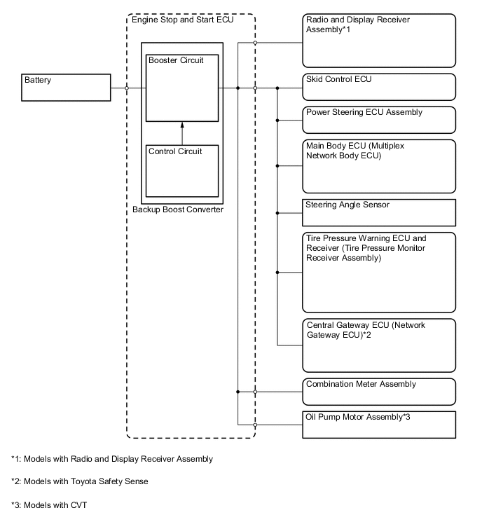
The backup boost converter uses a semiconductor relay. The semiconductor relay also functions as a fuse. When overcurrent is detected, the relay is turned off to protect the circuit.
-
The backup boost converter supplies battery voltage to help make up for the voltage drop that occurs when the engine is restarted. This prevents the operation of the following equipment from being interrupted due to low battery voltage.
-
Power Steering ECU assembly
-
Skid Control ECU
-
Main Body ECU (Multiplex Network Body ECU)
-
Combination Meter Assembly
-
Oil Pump Motor Assembly
-
Radio and Display Receiver Assembly
-
Steering Angle Sensor
-
Tire Pressure Warning ECU and Receiver (Tire Pressure Monitor Receiver Assembly)
-
Central Gateway ECU (Network Gateway ECU)
-
-
-
-
OPERATION
-
Combination Meter Assembly (Models with Monochrome Type Multi-information Display)
-
The combination meter receives the idling on/off signals from the engine stop and start ECU.
-
Press the ODO/TRIP DISPLAY switch several times to change the multi-information display and display the idle stop time.
-
ECO Odometer Display: Total idle stop time since the last time the reset was mode. The reset can be performed by pressing and holding the ODO/TRIP DISPLAY switch. (Total idle stop time is not erased by turning the ignition switch off.)
-
-
System operation status and warnings are known to the driver by the stop and start indicator light, stop and start cancel indicator light and buzzer.
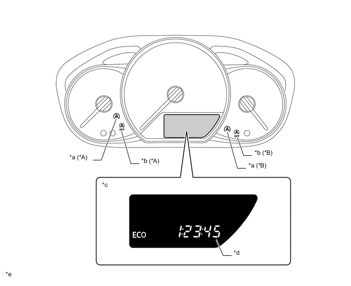
*A Models without Toyota Safety Sense *B Models with Toyota Safety Sense *a Stop and Start Indicator Light *b Stop and Start Cancel Indicator Light *c Multi-information Display *d Eco Time, Eco Odometer *e The illustrations shown are examples only. - - Multi-information Display Function Item Function Eco Time Idling stop time since last time ignition switch turned ON. Eco Odometer Idling stop time since counter was last reset. Stop and Start Indicator Light Operation (Models with M/T) Item Condition Stop and Start Indicator Light Buzzer System Operating (Engine is stopped) The vehicle is operating normally. Illuminates Does not sound The shift lever is operated without depressing the clutch pedal. Blinks* Sounds Stop and Start Indicator Light Operation (Models with CVT) Item Condition Stop and Start Indicator Light Buzzer System Operating (Engine is stopped) The vehicle is operating normally. Illuminates Does not sound When the shift lever is in D or M, the driver's door is opened. Blinks* Sounds Tech Tips
*: The blinking interval is 0.15 seconds.
Stop and Start Cancel Indicator Light Operation Condition Stop and Start Cancel Indicator Light The vehicle is stopped and system operation conditions are met. OFF While the stop and start system prevents the engine stop control from operating. Illuminates When the stop and start system cancel switch assembly (warning canceling switch assembly) is on. When any Diagnostic Trouble Code (DTCs) are detected. Blinks* When the number of times the starter assembly has been operated exceeds the threshold. Tech Tips
*: The blinking interval is 0.5 seconds.
-
-
Combination Meter Assembly (Models with Color Type Multi-information Display)
-
The combination meter assembly receives the idling on/off signals from the engine stop and start ECU.
-
Operating the steering pad switch assembly and selecting the changes to the stop and start screen.
-
The system operation status or warning information is indicated to the driver through the following means:
-
Illuminating or blinking the stop and start indicator light and stop and start cancel indicator light.
-
Sounding a buzzer.
-
Displaying other information on the multi-information display.
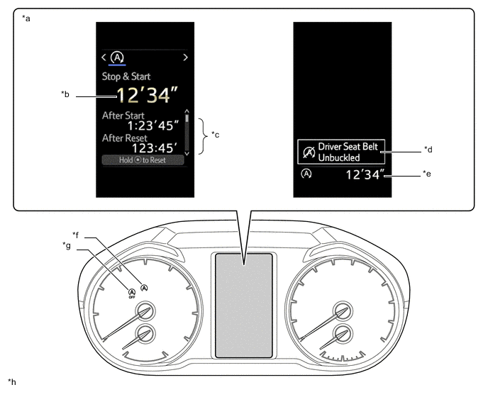
*a Multi-information Display *b Current Vehicle Stop Idling Stop Time, Status *c Idling Stop Time after Engine Start, Idling Stop Time after Reset, Fuel Saved after Engine Start, Fuel Saved after Reset *d Status *e Current Vehicle Stop Idling Stop Time *f Stop and Start Indicator Light *g Stop and Start Cancel Indicator Light *h The illustrations shown are examples only. Multi-information Display Function Item Function Current Vehicle Stop Idling Stop Time Receives idling stop signal from engine stop and start ECU and displays idling stop time. Status Warning/advice display. Idling Stop Time after Engine Start Idling stop time since last time ignition switch turned ON. Idling Stop Time after Reset Idling stop time since counter was last reset. Fuel Saved after Engine Start Amount of fuel saved since last time ignition switch turned ON. Fuel Saved after Reset Amount of fuel saved since counter was last reset. Setting Screen Pop-up Display Switches between display/non-display of the "Duration" and "Status" interrupt display. Stop and Start Indicator Light Operation (Models with M/T) Item Condition Stop and Start Indicator Light Buzzer System Operating (Engine is stopped) The vehicle is operating normally. Illuminates Does not sound The shift lever is operated without depressing the clutch pedal. Blinks* Sounds Stop and Start Indicator Light Operation (Models with CVT) Item Condition Stop and Start Indicator Light Buzzer System Operating (Engine is stopped) The vehicle is operating normally. Illuminates Does not sound When the shift lever is in D or M, the driver's door is opened. Blinks* Sounds Tech Tips
*: The blinking interval is 0.15 seconds.
Multi-information Display Function Stop and Start System Condition Multi-information Display Message*1 Vehicle Condition When the engine cannot be stopped by the stop and start system 
"Battery Charging"
-
The battery charge amount may be low.
-
A refresh charge may be occurring.
"For Brake System"
-
The brake booster load decreased.
-
The vehicle is operated at a high elevation.
"For Climate Control"
-
The air conditioning system is being used when the ambient temperature is high or low.
-
Windshield defogger is pressed.
"Bonnet Open" The engine has been started with the hood opened. "Driver Seat Belt Unbuckled" The driver seat belt is not fastened. When the engine automatically restarts while stopped by the atop and start system "Driver Seat Belt Unbuckled" The driver seat belt is not fastened. "For Brake System" The brake pedal is strongly depressed further or pumped. "Bonnet Open" The hood is opened during idling stop. "For Climate Control"
-
The air conditioning system is turned on or the air conditioning is being used.
-
Windshield defogger is turned on.
"Battery Charging" The battery charge amount may be low. Display of prohibition status of engine restart during idling stop operation*2 - "Stop & Start system active. Shift to N and depress clutch to restart." The shift lever is moved from N to another position without depressing the clutch pedal. Stop and start system may be malfunctioning - "Stop & Start system malfunction. Visit your dealer." - Tech Tips
*1: With regard to the stop and start system condition, the messages displayed on the multi-information display are listed in order with the highest priority first.
*2: Models with M/T
-
-
-
-
DIAGNOSIS
-
When the engine stop and start ECU detects a malfunction and CAN communication is normal, the engine stop and start ECU records information related to the fault. Furthermore, the stop and start cancel indicator light in the combination meter assembly blinks to inform the driver that all CAN communication are normal.
-
The engine stop and start ECU will also store the Diagnostic Trouble Code (DTC) of the malfunctions. The DTC can be read using the Global TechStream (GTS).
-