STOP AND START
-
OPERATING CONDITION
Component Function Engine Stop and Start ECU Sends either an engine stop or restart signal to the ECM according to the signals from each sensor and switch. Backup Boost Converter (Eco Run Vehicle Converter Assembly)
-
Supplies battery voltage to help make up for the voltage drop that occurs when the engine is restarted, preventing the operation of various systems from being interrupted due to low battery voltage.
-
Supplies battery voltage to the oil pump motor assembly.*1
Oil Pump Motor Assembly*1 Holds the CVT oil pressure while idle stop. This integrates the oil pump motor driver. Clutch Upper Switch*2 Recognizes that the clutch pedal is not depressed and sends a signal to the engine stop and start ECU. Clutch Lower Switch*2 Recognizes that the clutch pedal is depressed and sends a signal to the engine stop and start ECU. Neutral Position Switch*2 Recognizes that the shift lever is in N and sends a signal to the engine stop and start ECU. Park/neutral Position Switch Assembly*1 Recognizes that the shift lever position and sends a signal to the engine stop and start ECU. Blower Temperature Sensor Detects the temperature of air from the blower and sends a signal to the engine stop and start ECU. Brake Vacuum Pressure Sensor Detects the brake booster vacuum pressure and sends a signal to the engine stop and start ECU. Engine Hood Courtesy Switch Detects whether the hood is open or closed and sends a signal to the engine stop and start ECU. Front Door Courtesy Light Switch (Driver) Detects whether the door is open or closed and sends a signal to the engine stop and start ECU via the main body ECU (multiplex network body ECU) via CAN communication. Front Seat Belt Buckle Switch (Driver)*1 Detects whether or not the driver's seat belt has been fastened, and sends a signal to the engine stop and start ECU via the main body ECU (multiplex network body ECU) via CAN communication. Battery Current Sensor (Included in Battery Temperature Sensor) Detects the battery temperature and how much power is being charged to or discharged from the battery and sends signals to the engine stop and start ECU. These signals are used to protect the battery. Air Conditioning Amplifier Assembly Sends an outside temperature signal and A/C switch signal to the engine stop and start ECU. Blower Switch Sends a blower operation signal to the engine stop and start ECU. Combination Meter Assembly Stop and Start Indicator Light Turns on when the engine is stopped due to stop and start system control. Stop and Start Cancel Indicator Light
-
Turns on to inform the driver that the system has been disabled when.
-
Stop and start system operation is prohibited by stop and start system cancel switch assembly.
If a system malfunction is detected, the stop and start cancel indicator light blinks to inform the driver. Multi-information Display (ECO Time and ECO Odometer) Displays the total amount of engine stoppage time occurring since the last reset. Stop and Start System Cancel Switch Assembly The operation of the system can be cancelled by pressing the stop and start system cancel switch assembly. Pressing the switch again or turning the power source off and back on restores the operation of the system. ECM Sends various information about engine conditions to the engine stop and start ECU. Skid Control ECU (Brake Actuator Assembly) Sends a vehicle speed signal to the engine stop and start ECU. Airbag Sensor Assembly Sends airbag deployment information in the event of a collision and deceleration signal to the engine stop and start ECU.
-
*1: Models with CVT
-
*2: Models with M/T
-
-
OPERATING CONDITION
-
Operating conditions at engine stop and restart
-
The engine may stop if all of these conditions are detected.
Item Operating Condition Engine Stop Engine Coolant Temperature 40°C to 105°C (104°F to 221°F) CVT Oil Temperature*1 25°C to 100°C (77°F to 228°F) Driver Door Closed Brake Booster Vacuum Sufficient brake booster vacuum Stop and Start System Cancel Switch Assembly Off condition Road Gradient*1 8° or less Vehicle Speed
-
0 km/h (0 mph)
-
Vehicle has been driven at 7 km/h (4.4 mph) or more (first operation of control only, second operation of control is 2 km/h (1.2 mph) or more).
Engine Speed 1200 rpm or less Clutch Pedal*2 Released Shift Lever Position N, P*1, D*1 Driver's Seat Belt*1 Fastened Engine Hood Closed Battery Voltage
-
7.6 V or more at engine start and 8.16V or more at engine cranking.*1 (49 msec after engine start)
-
7.6 V or more at engine start.*2
Battery Temperature -15°C to 75°C (5°F to 167°F) Battery Integrated Current*3
-
0 A-sec or more: After engine start by ignition switch operation
-
After the integrated current value has increased to 0 A-sec or more at least once ignition switch ON:
-
More than -3564 A-sec*1 (-3110 A-sec*2): When a low battery temperature condition is not detected (the battery temperature is 11°C (52°F) or more).
-
More than -990 A-sec*1 (-864 A-sec*2): When a low battery temperature condition is not detected (the battery temperature is less than 10°C (50°F)).
Air Conditioning Off or on with an outside temperature of 25°C (77°F) or lower and an evaporator temperature of 8°C (46°F) or lower. Heater Off or on with an outside temperature of 10°C (50°F) or higher and an engine coolant temperature of 55.5°C to 65.5°C(132°F to 150°F) or higher. ECM Learning Completed
-
*1: Model with CVT
-
*2: Model with M/T
-
*3: Regarding Battery Integrated Current In the stop and start system, the engine stop and start ECU switches the system control mode (stop and start system control permitted/prohibited) based on the battery condition (charge/discharge condition) to protect the battery and to ensure stable engine restarting performance. The battery charge-discharge condition is determined from the integrated current value calculated from the battery current sensor signal. The integrated current value is obtained by multiplying the current (ampere) detected from the battery current sensor by the time (seconds), and it is expressed in the unit A-sec. This can be measured by intelligent tester. The engine stop and start ECU determines the power charge based on the integrated current value, and it prohibits stop and start system control if the value is below the threshold, because the battery might not be able to start the engine. The threshold values according to the battery temperature and battery charge condition.
-
-
The engine will restart if any of these conditions are detected.
Item Operating Condition Engine Restart Brake Booster Vacuum The brake booster vacuum is insufficient. Air Conditioning The timer in the air conditioning amplifier assembly operates when the air conditioning is on. Heater The blower output temperature drops when the heater is on. Air Conditioning / Heater The A/C switch or blower switch is turned on manually while the engine is stopped. Stop and Start System Cancel Switch Assembly The stop and start system switch is turned on. Battery When battery voltage is less than 11.4 V. Engine Hood The engine hood is opened. Vehicle Speed Vehicle speed signal is input. Brake Pedal*1 Released. Accel Pedal*1 Depressed. Clutch Pedal*2 Depressed. Shift Lever*1 N or P to D position. Driver's Door*1 Opened. Driver's Seat Belt*1 Unfastened.
-
*1: Models with CVT
-
*2: Models with M/T
-
-
-
-
SYSTEM CONTROL
-
Early Stage Injection Control
-
Early stage injection control shortens the time it takes the engine to restart after the stop and start system stops the engine, thus allowing smooth initial acceleration.
-
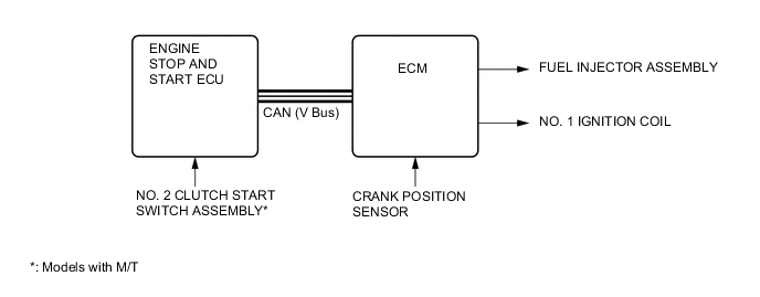
The ECM memorizes the crankshaft angle detected by the crank position sensor when the engine is stopped by the stop and start system.
-
The ECM judges the injection required and decides which cylinder to ignite when the driver does restart operation. The ECM then uses this information as it starts the engine.
-
-
Stopping Position Control (Model with M/T)
-
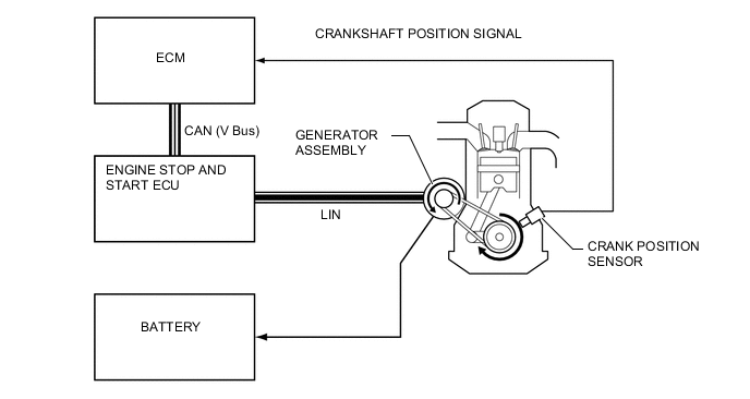
While the engine stopping operation is performed, the ECM uses ignition timing and generator assembly load torque to control the crankshaft position so that it is at the optimal position for engine start.
-
The ECM calculates the amount of electricity that needs to be generated to produce the load torque necessary for controlling and sends requests for electricity generation to the generator assembly via the engine stop and start ECU. The ECM inputs the applied crankshaft position signal and performs feedback.
-
-
Hill-start Assist Function
-
The driving force (creep phenomenon) of a former CVT vehicle is regulated by depressing the brake pedal while stopping, and the driving force is transmitted by releasing the brake pedal when starting the vehicle. However, when starting a stop and start system equipped vehicle with its engine stopped due to the activation of the idle stop function, there is a short time delay of the driving force to be generated as the engine will start after the brake pedal is released.
-
The hill-start assist function is a system to assist starting of a stop and start system equipped vehicle on a slope to deal with the reason described above, retaining the brake hydraulic pressure until the driving force is generated, and releasing the brake hydraulic pressure automatically after the driving force is generated.
-
-
System Prohibit Control
-
For safety, battery protection, comfort and ECM learning reasons, the engine stop and start ECU prohibits stop and start system operation if any one of the following conditions is met.
Prohibition Reason Condition Safety If the engine is started with the hood open, such as when jump starting, engine restart operation cannot be ensured. Therefore, stop and start system operation will be prohibited. The operation of the system will be restored for the next trip. If the driver door or hood is opened before the engine stops, stop and start system operation will be prohibited for safety reasons. The brake booster vacuum is insufficient. If the air conditioning is on when the outside temperature is low, stop and start system operation will be prohibited. If the engine stop and start ECU receives an airbag deployment signal in the event of a collision, stop and start system operation will be prohibited for safety reasons. Battery Protection If the electrical load is high and the engine is stopped for a long period of time, stop and start system operation will be prohibited. A refresh charge is performed every time the vehicle is driven for a total of 20 hours. During the refresh charge, which takes 30 minutes to 1 hour, stop and start system operation will be prohibited. If the ratio of the engine stop duration to the time the ignition switch is being turned to ON exceeds a certain value, the stop and start system will be prevented from operating.
-
If the battery integrated current is less than 0 A-sec after engine start by ignition switch operation, the stop and start system operation will be prohibited.
-
After the integrated current value increases to 0 A-sec or more once:
-
-3564 A-sec*1 (-3110 A-sec*2) or less: When the battery temperature is 10°C(50°F) or more, stop and start system operation will be prohibited
-
-990 A-sec*1 (-864 A-sec*2) or less: When the battery temperature is less than 10°C(50°F), stop and start system operation will be prohibited
Comfort If the air conditioning is on when the outside temperature is high and the evaporator temperature is high, stop and start system operation will be prohibited. If the heater is on when the outside temperature is low and the engine coolant temperature is low, stop and start system operation will be prohibited. If the front DEF switch and blower switch are on, stop and start system operation will be prohibited (Models with automatic air conditioning). ECM Learning ECM learning is not complete.
-
*1: Model with CVT
-
*2: Model with M/T
-
-
-
Warning Control
-
If any of the following operations are performed while the engine is stopped due to system control, the system will not restart the engine. The driver will be warned by the buzzer sounds, or engine stalled.
Operation Warning Control Driver door is opened. Buzzer sounds. Hood is opened. The engine changes to 'stalled' or restarted. Shift lever is moved without depressing the brake pedal. *1 Buzzer sounds. Shift lever is moved without depressing the clutch pedal. *2 Buzzer sounds.
-
*1: Model with CVT
-
*2: Model with M/T
-
-
-
-
CONSTRUCTION
-
Backup Boost Converter (Eco Run Vehicle Converter Assembly)
-
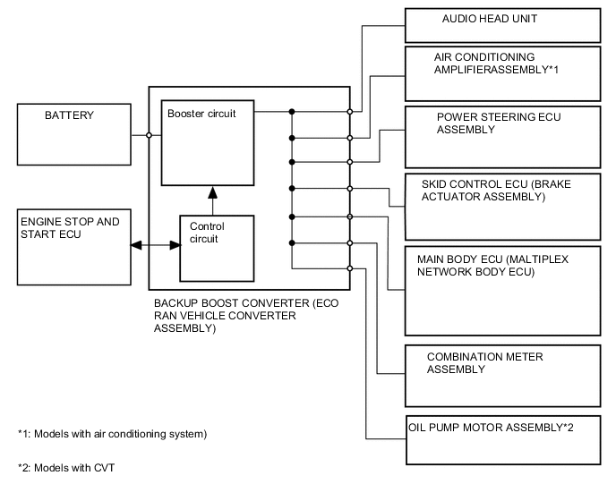
The backup boost converter (eco run vehicle converter assembly) uses a semiconductor relay. The semiconductor relay also functions as a fuse. When overcurrent is detected, the relay is turned off to protect the circuit.
-
The backup boost converter (eco run vehicle converter assembly) supplies battery voltage to help make up for the voltage drop that occurs when the engine is restarted. This prevents the operation of the following equipment from being interrupted due to low battery voltage.
-
Audio Head Unit
-
Air Conditioning Amplifier Assembly
-
Power Steering ECU assembly
-
Skid Control ECU (Brake Actuator Assembly)
-
Main Body ECU (Maltiplex Network Body ECU)
-
Combination Meter Assembly
-
Oil Pump Motor Assembly
-
-
-
Permanently Engaged Gear Mechanism
-
In this permanently engaged gear mechanism, the bearing, one-way clutch, and ring gear are positioned between the crankshaft and the flywheel or drive plate and ring gear sub-assembly, allowing the pinion gear of the starter and the ring gear to be continuously engaged.
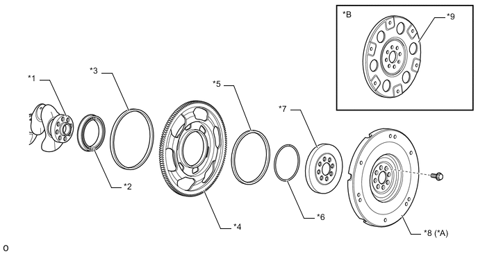
Text in Illustration *A Models with M/T *B Models with CVT *1 Crankshaft *2 Bearing *3 Outer Oil Seal *4 Ring Gear Sub-assembly *5 Inner Oil Seal *6 Snap Ring *7 One-way Clutch Assembly *8 Flywheel *9 Drive Plate and Ring Gear Sub-assembly - - -
When the engine is being started or restarted, the starter starts operating and the ring gear sub-assembly rotates. Then, the inner race of the ring gear sub-assembly pushes the sprags against the outer race, locking the ring gear sub-assembly to the crankshaft, thus turning the crankshaft and starting the engine.
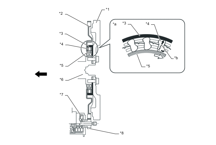
Text in Illustration (Models with M/T:) *1 Flywheel *2 Ring Gear Sub-assembly *3 Outer Race (One-way Clutch Assembly) *4 Sprag *5 Inner Race (Ring Gear Sub-assembly) *6 Crankshaft *7 Starter *8 Pinion Gear *a Front-view *b Torque Transmission 
Engine Front - - 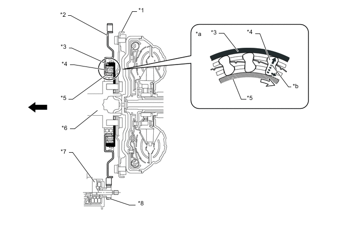
Text in Illustration (Models with CVT:) *1 Drive Plate and Ring Gear Sub-assembly *2 Ring Gear Sub-assembly *3 Outer Race (One-way Clutch Assembly) *4 Sprag *5 Inner Race (Ring Gear Sub-assembly) *6 Crankshaft *7 Starter *8 Pinion Gear *a Front-view *b Torque Transmission Engine Front - - -
After the engine has started, the crankshaft starts turning faster than the ring gear sub-assembly. When this happens, the sprags of the one-way clutch are released and the ring gear sub-assembly and the crankshaft are unlocked. If the starter stops, the ring gear subassembly also stops.
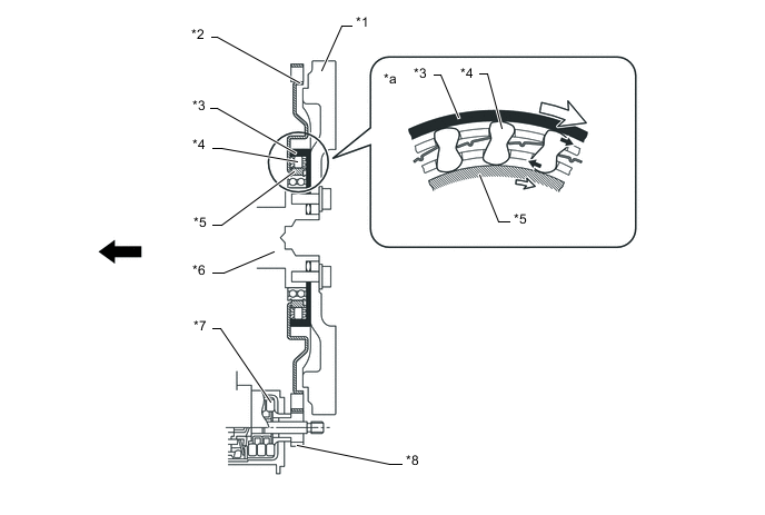
Text in Illustration (Models with M/T:) *1 Flywheel *2 Ring Gear Sub-assembly *3 Outer Race (One-way Clutch Assembly) *4 Sprag *5 Inner Race (Ring Gear Sub-assembly) *6 Crankshaft *7 Starter *8 Pinion Gear *a Front-view - - Engine Front - - 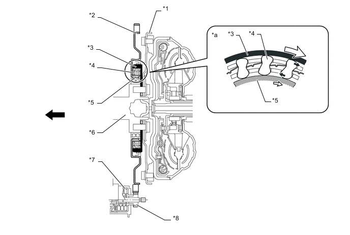
Text in Illustration (Models with CVT:) *1 Drive Plate and Ring Gear Sub-assembly *2 Ring Gear Sub-assembly *3 Outer Race (One-way Clutch Assembly) *4 Sprag *5 Inner Race (Ring Gear Sub-assembly) *6 Crankshaft *7 Starter *8 Pinion Gear *a Front-view - - Engine Front - -
-
-
-
OPERATION
-
Combination Meter Assembly
-
The combination meter receives the idling on/off signals from the engine stop and start ECU.
-
Press the ODO/TRIP DISPLAY switch several times to change the multi-information display and display the idle stop time.
-
Eco Odometer Display: Total idle stop time since the last time the reset was mode. The reset can be performed by pressing and holding the ODO/TRIP DISPLAY switch (not erased by turn the ignition switch off).
-
-
System operation status and warnings are known to the driver by the stop and start indicator light, stop and start cancel indicator light and buzzer.
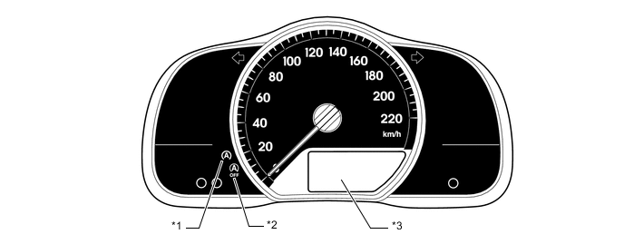
Text in Illustration *1 Stop and Start Indicator Light *2 Stop and Start Cancel Indicator Light *3 Multi-information Display - - Stop and Start Indicator Light Operation Item Condition Stop and Start Indicator Light Buzzer System Operating (Engine is stopped) The vehicle is operating normally. Illuminates Does not sound The shift lever is operated without depressing the clutch pedal. Sounds The driver's door is opened. Stop and Start Indicator Light Operation (Models with CVT) Item Condition Stop and Start Indicator Light Buzzer System Operating (Engine is stopped) The vehicle is operating normally. Illuminates Does not sound The shift lever is operated without depressing the brake pedal. Blinks* Sounds When the shift lever is in D, the driver's seat belt is unfastened and the driver's door is opened. Tech Tips
*: The blinking interval is 0.13 seconds.
Condition Stop and Start Cancel Indicator Light The vehicle is stopped and system operation conditions are met. OFF While the stop and start system prevents the engine stop control from operating. Illuminates When the stop and start system cancel switch assembly is ON. Any Diagnostic Trouble Code (DTCs) are detected. Blinks* The number of times the starter has been operated exceeds the threshold. Tech Tips
*: The blinking interval is 0.5 seconds.
-
-
-
DIAGNOSIS
-
When the engine stop and start ECU detects a malfunction and CAN communication is normal, the engine stop and start ECU records information related to the fault. Furthermore, the Stop and Start indicator light in the combination meter assembly blinks to inform the driver that all CAN communication are normal.
-
The engine stop and start ECU will also store the Diagnostic Trouble Code (DTC) of the malfunctions. The DTC can be read using the intelligent tester.
-