MULTI-MODE MANUAL TRANSAXLE SYSTEM
-
FUNCTION OF MAIN COMPONENTS
-
The main components of the EC65A M-MT system are as follows:
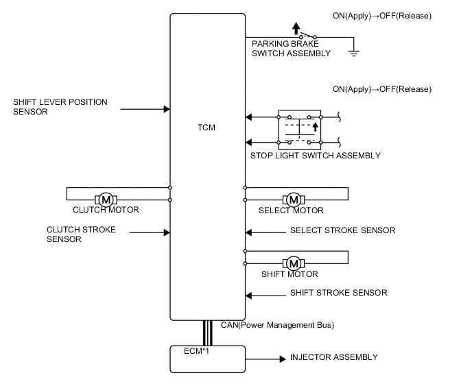
Component Function Clutch Actuator Assembly Clutch Motor The clutch motor is actuated by the TCM and engages and disengages the clutch. Clutch Stroke Sensor Detects the amount of the clutch stroke from the rotational angle of the reduction mechanism and relays this information to the TCM in the form of feedback signals. Shift and Select Actuator Assembly Shift Motor The shift motor is actuated by the TCM and performs the shift operation of the shift and select lever shaft. Shift Stroke Sensor Detects the length of the shift stroke of the gear shift fork from the rotational angle of the shift and select lever shaft and relays this information to the TCM in the form of feedback signals. Select Motor The select motor is actuated by the TCM and performs the select operation of the shift and select lever shaft. Select Stroke Sensor Detects the length of the select stroke of the gear shift fork from the rotational angle of the shift and select lever shaft and relays this information to the TCM in the form of feedback signals. Floor Shift Shift Lever Assembly Shift Lever Position Sensor Outputs the shift lever position or shift request ("+" or "-") from the on/off combination of the 8-contact switch. Transmission Shift Main Switch Outputs the shift mode (M-mode or E-mode) from the on/off signal to the TCM. Shift Lock Solenoid The shift lock solenoid is actuated by the TCM and restricts the movement of the shift lever. Pattern Select Switch Assembly Switches the driving pattern ([E] or [Es]) in E-mode. Shift Paddle Switch (Transmission Shift Switch Assembly) Enables the driver to select a desired gear by operating the switch while driving in E-mode or M-mode. Combination Meter Assembly M-MT Warning Light Illuminates to alert the driver when a malfunction occurs in the M-MT system. Shift Position and Shift Range Indicator
-
Indicates the present shift lever position when the shift lever is in N or R.
-
Indicates the present gear when in M-mode or temporary M-mode.
-
This indicator light flashes if the actual gear and the shift lever position do not match.
[E]/[Es] Indicator
-
Illuminates the [E] indicator when the normal [E] pattern is selected.
-
Illuminates the [Es] indicator when the sporty [Es] pattern is selected during the normal [E] pattern driving in E-mode.
[M] Indicator The [M] indicator illuminates when the shift lever is in M. Buzzer
-
Sounds a buzzer during system warning.
-
Sounds if the driver door is opened while the engine is idling and the shift lever is in E, M, or R.
Accelerator Pedal Position Sensor
-
Detects the accelerator pedal position and outputs it to the ECM.
-
Sends a kick down on signal to the ECM when the accelerator pedal position sensor detects the specified accelerator pedal depression amount.
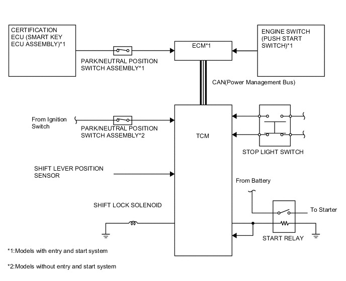
Transmission Revolution Sensor Detects the input shaft speed of the transaxle and outputs it to the TCM. Park/Neutral Position Switch Assembly
-
Detects the neutral position of the transaxle and outputs it to the TCM. *1
-
Detects the neutral position of the transaxle and outputs it to the Certification ECU (Smart Key ECU Assembly). *2
Stop Light Switch Assembly Detects that the brake pedal is applied and outputs this information to the TCM. Parking Brake Switch Assembly Detects the parking brake lever operating signal and outputs it to the TCM. Starter Relay The TCM restricts the operation of the starter relay in accordance with the selected gear and the braking conditions, in order to control the operation of the starter. TCM
-
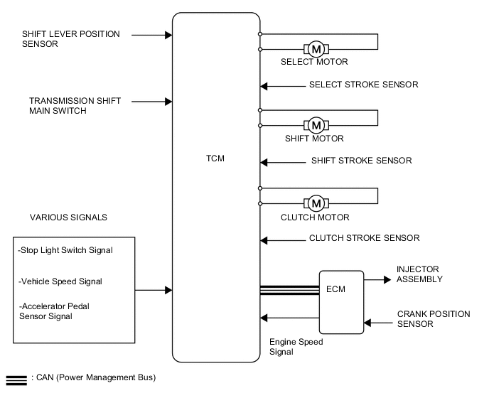
Controls the M-MT system; in addition, requests the ECM to control the engine output during upshift or downshift via CAN communication.
-
When the TCM detects a malfunction, the TCM makes a diagnosis and memorizes the failed section. Furthermore, the M-MT warning light illuminate to inform the driver.
ECM
-
Outputs each sensor information to the TCM.
-
Performs engine output control in accordance with requests from the TCM.
Certification ECU (Smart Key ECU Assembly) *2 Receives signals from the part/neutral position switch assembly and transmits those signals to the ECM. Main Body ECU (Multiplex Network Body ECU) Transmits Driver side door courtesy switch signals to the ECM.
-
*1: Models without entry and start system
-
*2: Models with entry and start system
-
-
-
SYSTEM CONTROL
-
Control List
-
The electronic control system of the EC65A M-MT consists of the controls listed below.
Control Outline Engine Starting Control The TCM permits the operation of the starter to start the engine only when the brake pedal is depressed and the shift lever is in N. Vehicle Starting Off Control When the vehicle starts off in the 1st or 2nd or reverse, the TCM partially engages the clutch. Thus, it enables the vehicle to start off slowly without requiring the operation of the accelerator pedal. Shifting Control
-
Shifting control consists of E-mode control, M-mode control.
-
In E-mode, the TCM selects an optimal gear to suit the driving conditions.
-
In M-mode, the TCM shifts into the gear selected by the driver.
-
If the shift paddle switches (transmission shift switch) are operated in E-mode, the TCM shifts into the gear selected by the driver.
Shift Pattern Control
-
In E-mode, the driver can select from 2 (E, Es) shift patterns:
-
The normal [E] pattern places emphasis on fuel economy.
-
The sporty [Es] pattern enables sporty driving.
Kick Down Control While the vehicle is being driven in E-mode, this control enables the TCM to perform downshifts in accordance with the actual vehicle speed when the driver fully depresses the accelerator pedal. Uphill/Downhill Shift Control While the vehicle is being driven in E-mode, this control restricts 2nd, 3rd, 4th, 5th or 6th upshifts or provides appropriate engine braking in order to enable the TCM to determine whether the vehicle is traveling uphill or downhill. Delta Throttle Acceleration Control When the TCM detects the accelerator pedal rapidly being moved by driver, M-MT system controls shift, restricting downshifting during accelerating and upshift during decelerating. Vehicle Stopping Control
-
When the input shaft speed decreases to a predetermined level while the vehicle is in motion, the TCM disengages the clutch to prevent the engine from stalling.
-
When the vehicle is stopped and the shift lever is in E or M, this control automatically shifts to 1st gear, thus making it unnecessary for the driver to shift when the vehicle is started off again.
Parking Control
-
When the shift lever is in R, E, or M and the ignition switch is turned off, the TCM operates as follows:
-
The shift lever is locked at the current position. This prevents the shift lever position and selected gear from becoming mismatched.
-
Then, the TCM engages the clutch with the gear in the 1st or reverse to park the vehicle with the gear engaged.
Retry Control When shifting to the target gear is not successful, the TCM retries gear shifting. Shift Protection Control
-
When one of the following conditions are met, the TCM performs shift protection control and warns the driver to protect the gears, clutch and engine:
-
Upshift occurs when the engine speed is lower than the specified value.
-
Downshift occurs when the engine speed is higher than the specified value.
-
The shift lever is moved to R when the vehicle speed is 6.0 km/h (3.7 mph) or more.
-
The shift to 1st request signal is input when the outside air temperature is low.
Fail-safe Even if a malfunction is detected in the sensors or actuators, the TCM performs fail-safe control to prevent the vehicle's driveability from being affected significantly. Diagnosis When the TCM detects a malfunction, the TCM makes a diagnosis and memorizes the information related to the fault. -
-
-
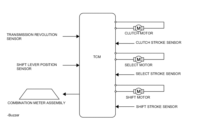
Engine Starting Control
-
When the ignition switch is turned to ON and the brake pedal is depressed, the TCM turns on the shift lock solenoid in order to release shift lock.
-
When the shift lever is moved to N, the TCM detects that the shift lever is in N using the shift lever position sensor.
-
When the ignition switch is turned to ON, the start signal is sent to the TCM through the park/neutral position switch assembly. When the ECU receives the signal, the starter relay is turned on to cause the engine to start.
-
-
Vehicle Starting Off Control
-
When the shift lever is in E, M or R, the TCM controls the shift and select motors to change the appropriate gear.
-
When the foot brake and parking brake are released, the TCM commands the clutch motor to partially engage the clutch.
-
As a result, the vehicle can be driven slowly forward without requiring the driver to depress the accelerator pedal.
-
The TCM calculates the clutch disc temperature based on information from the clutch stroke sensor, engine speed signal, and input shaft speed signal. If the TCM determines that the load applied to the clutch is large* according to this information, it sounds the buzzer in the combination meter assembly to alert the driver to avoid clutch disc damage.
Tech Tips
*: The vehicle is stopped on an incline or with a chock block when the clutch is partially engaged and the brake pedal is not depressed.
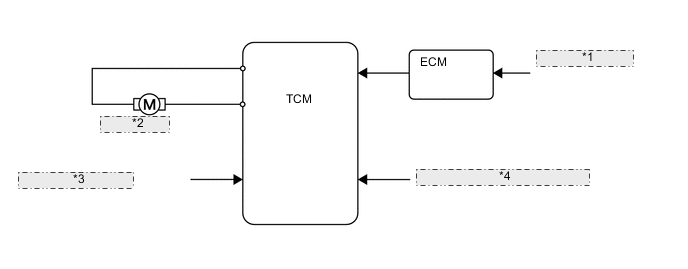
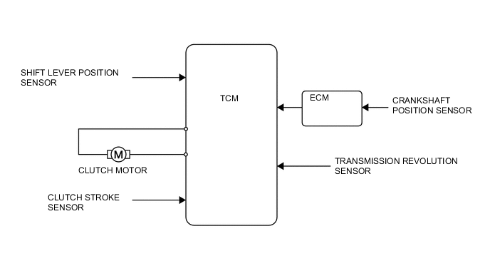
*1 CRANKSHAFT POSITION SENSOR *2 CLUTCH MOTOR *3 CLUTCH STROKE SENSOR *4 TRANSMISSION REVOLUTION SENSOR -
When the engine speed is high and the shift lever is moved from N to E, M, or R, the TCM sounds the buzzer in the combination meter assembly to alert the driver and controls the clutch motor in order to prevent the vehicle from moving suddenly.
-
-
E-mode Shifting Control
-
In E-mode, the TCM automatically selects an optimal gear that suits the driving conditions.
-
When the shift lever is moved to E, the TCM activates E-mode control.
-
The TCM calculates the suitable gear according to the driving conditions determined from various signals, and controls the clutch actuator assembly and shift and select actuator assembly.
-
The TCM sends a signal to request or fuel injection control, achieving smooth shifts.
-
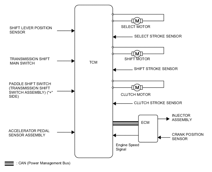
TCM can hold the gear that the driver selects with the shift paddle switch (transmission shift switch) even E-mode.
-
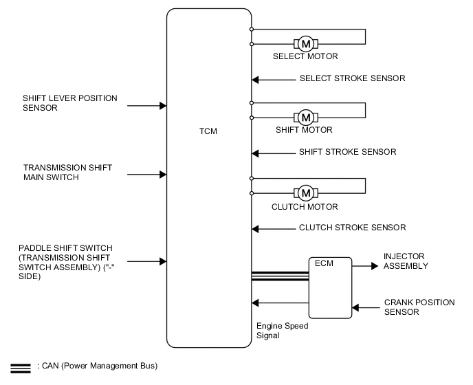
The gear can be selected with the shift paddle switch (transmission shift switch)"+" or "-" like M-mode.
-
If the vehicle is gotten below condition, the system release the gear which is held by above operation.
-
Downshifting (including decelerating, kick down, and so on)
-
"+" switch is pressed for around 1 second.
-
The accelerator pedal is continuously depressed for a certain period of time.
-
-
-
M-mode Shifting Control (Upshifting)
-
In M-mode, the TCM performs gear shift control to select the gear chosen by operating the shift lever or shift paddle switch (transmission shift switch) to "+".
-
When the shift lever is moved to M, the TCM uses M-mode control.
-
If the shift lever or shift paddle switch (transmission shift switch) is operated to "+", the TCM controls the clutch motor to release the clutch. If the driver is depressing the accelerator pedal at this time, the TCM sends a signal to the ECM to request fuel injection control, suppressing engine speed increase.
-
The TCM controls the shift and select actuator assembly to upshift the gear.
-
The TCM controls the clutch motor to engage the clutch.
-
If the ECU determines that the engine speed will become less than approximately 1000 rpm due to an upshift, the upshift is not performed due to shift protection control.
-
-
-
M-mode Shifting Control (Downshifting)
-
In M-mode, the TCM performs gear shift control to select the gear chosen by operating the shift lever or shift paddle switch (transmission shift switch) to "-".
-
When the shift lever is moved to M, the TCM activates the M-mode control.
-
If the shift lever or shift paddle switch (transmission shift switch) is operated to "-", the TCM controls the clutch motor to release the clutch.
-
The TCM controls the shift and select actuator assembly to downshift the gear.
-
The TCM controls the clutch motor to engage the clutch.
-
If the ECU determines that the engine speed will become too high due to a downshift, the downshift is not performed due to shift protection control and the buzzer in the combination meter assembly sounds.
-
While driving the vehicle with a gear selected, if the vehicle speed becomes less than the specified minimum speed for that gear, the TCM automatically downshifts to improve driveability and prevent the engine from stalling.
-
-
-
Uphill/Downhill Shift Control
-
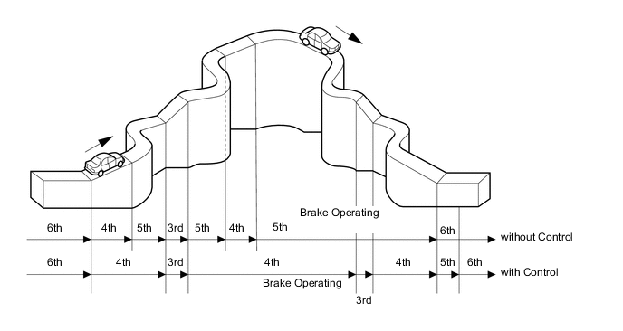
This control minimizes the gear shifting when the driver operates the accelerator pedal while driving on a winding uphill or downhill road in order to ensure comfortable driveability.
-
When the TCM determines that the vehicle is traveling uphill and before the transaxle attempts to upshift or after it finishes downshifting, the TCM prohibits the upshift until it determines that the vehicle has finished traveling uphill.
-
When the TCM determines that the vehicle is traveling downhill, the ECU maintains the present gear, and if the brake pedal is depressed, performs a downshift.
-
The actual acceleration calculated from the vehicle speed signal is compared with the reference acceleration (based on level road travel) stored in the ECM to determine uphill or downhill travel.
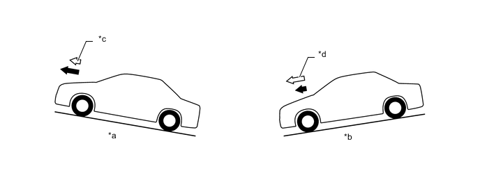
Text in Illustration *a Uphill *b Downhill *c Smaller *d Greater 
Reference Acceleration 
Actual Acceleration
-
-
Delta Throttle Acceleration Control
-
Delta throttle acceleration control, which operates in E-mode, has the following 2 control functions:
-
At sudden acceleration: The TCM determines that the driver intends sudden acceleration via the accelerator pedal position sensor and thus quickens the downshift timing.
-
At sudden deceleration: The TCM determines that the driver intends to decelerate via the accelerator pedal position sensor. Instead of upshifting, it maintains the current gear to ensure engine braking and also ensure the driving force when the accelerator is subsequently operated.
-
-
-
Vehicle Stopping Control
-
While driving, the TCM detects the input shaft speed based on the transmission revolution sensor signal. If the speed is less than a specified speed, the ECU partially releases the clutch to prevent the engine from stalling.
-
If the speed exceeds a specified speed, the ECU completely engages the clutch. The specified speed differs depending on the gear.
-
At this time, the ECU controls the shift and select actuator assembly to automatically downshift the vehicle to 1st gear when the shift lever is in M or E in order to start moving again.
-
When the shift lever is in R, the gears do not shift automatically.
-
In this situation, when the following conditions are met, the TCM sounds the buzzer in the combination meter assembly to alert the driver:
-
When all conditions listed for pattern 1 are met, the buzzer sounds after 10 seconds, and the transmission shifts to neutral.
-
When all conditions listed for pattern 2 are met, the buzzer sounds after 90 seconds, and the transmission shifts to neutral.
Pattern 1 Pattern 2
-
Vehicle is stopped.
-
Engine is running.
-
Shift lever is in E, M or R
-
Parking brake is applied.
-
Driver's door is opened.
-
Vehicle is stopped.
-
Engine is running.
-
Shift lever is in E, M or R.
-
Parking brake is applied.
-
-
-
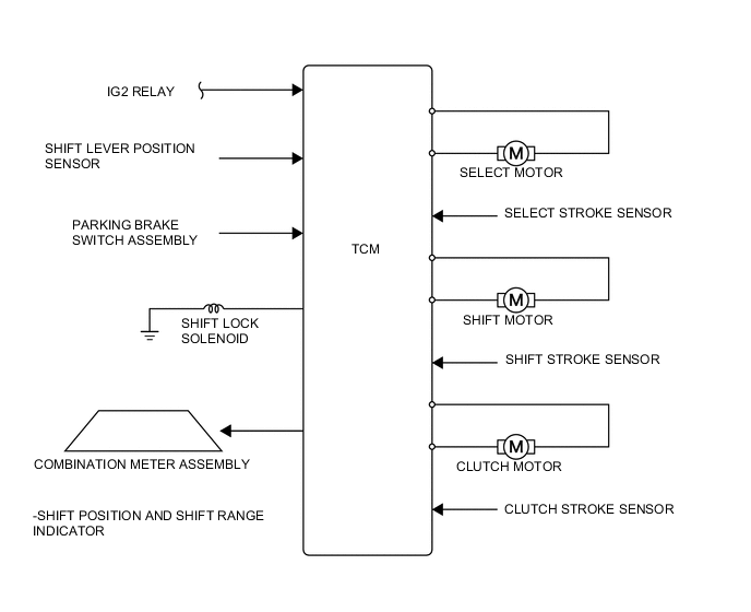
Parking Control
-
M-MT system has the function of gear parking. This procedure is below.
-
Apply the parking brake and move the shift lever to E, M or R. Then turn the ignition switch to ACC or off.
-
Then, the TCM activates the shift lock function to engage the clutch.
-
As a result, the vehicle can be parked with the transaxle in a gear that corresponds to the shift lever position.
-
The gear is indicated on the M-MT display in the combination meter for approximately 5 seconds after the ignition switch is turned off.
-
-
-
Retry Control
-
When shifting to a target gear is not successful, the TCM retries gear shifting.
Condition Retry Operation Warning
-
Vehicle is stopped.
-
Engine is stopped.
-
Shift lever is from N to E, M, or R.
-
If the transaxle does not shift from neutral to the target gear, the TCM performs the following operations:
-
Returns transaxle to neutral.
-
Shifts to another gear.
-
Shifts to the target gear.
-
If the transaxle does not shift to the target gear after the above operations have been repeated a few times, the TCM stops gear shifting and stands by in neutral.
Shift position indicator N blinks*
-
Vehicle is stopped.
-
Engine is running.
-
Shift lever is moved from N to E, M or R.
-
If the transaxle does not shift from neutral to the target gear, the TCM performs the following operations:
-
Returns to neutral.
-
Engages and disengages the clutch once.
-
Shifts to the target gear.
-
If the transaxle does not shift to the target gear after the above operations have been repeated a few times, the TCM stops gear shifting and stands by in neutral.
Shift position indicator N blinks* Buzzer in combination meter assembly sounds*
-
Vehicle is driven.
-
During upshifting or downshifting.
-
If the transaxle does not shift to the target gear, the TCM performs the following operations:
-
Returns to neutral.
-
Shifts again to the target gear.
-
If the transaxle does not shift to the target gear after the above operations have been repeated a few times, the TCM stops gear shifting and stands by in neutral.
-
-
Vehicle is driven.
-
Transaxle jumps out of gear.
-
If the transaxle pops out of gear unintentionally, the TCM performs the following operations:
-
Returns to neutral.
-
Shift to the target gear.
- Tech Tips
*: During retry operation
-
-
If the vehicle is standing-by in neutral due to one of the situations above, the driver should perform the following:
Condition Retry Operation
-
Vehicle is stopped.
-
Engine is stopped.
-
Turn the ignition switch to ON.
-
Depress the brake pedal.
-
Return the shift lever to N.
-
Move the shift lever to the target position again.
-
Turn the ignition switch off.
-
Vehicle is stopped with the engine running
-
Return the shift lever to N.
-
Move the shift lever to the target position again.
-
Driving (Upshifting or Downshifting)
-
-
-
Shift Protection Control
-
To protect the transaxle gears, clutch and engine, the TCM restricts shifting when one of the conditions indicated in the table below is met:
Condition System Operation Warning Upshift occurs when the engine speed is lower than the specified value. Shifting is rejected - Downshift occurs when the engine speed is higher than the specified value. Shifting is rejected Buzzer in combination meter assembly sounds twice The driver moves the shift lever to R at a vehicle speed of 6 km/h (4 mph) or more. (E → R, M → R or N → R) Shifting is rejected N position indicator blinks The driver downshifts to 1st gear at a low outside air temperature (Estimated transaxle oil temperature of - 25°C or below). Shifting is rejected (2nd gear is selected) -
-
-
-
FUNCTION
-
Floor Shift Shift Lever Assembly
-
The floor shift shift lever assembly mainly consists of the shift lever position sensor, transmission shift main switch and shift lock solenoid.
-
A shift lock uses a shift lock solenoid to restrict the movement of the shift lever. Shift lock control is performed during the engine starting control, vehicle stopping control, or parking control of the M-MT system.
-
A shift lock override button that can manually cancel the shift lock is provided.
-
The transmission shift main switch detects the side-to-side movement of the shift lever. It turns off when the shift lever is in R, N or E, and on in M, "+" or "-".
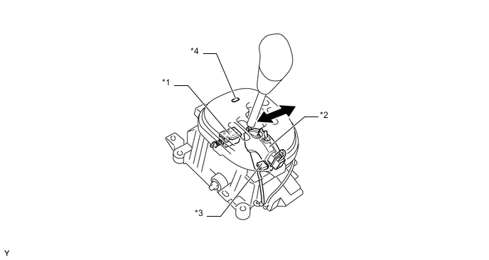
Text in Illustration *1 Shift Lock Solenoid *2 Shift Lever Position Sensor *3 Transmission Shift Main Switch *4 Shift Lock Override Button Side-to-side Movement - -
-
-
Pattern Select Switch
-
In the automatic shift mode (E-mode), the driver can select the automatic shift control patterns between the normal [E] pattern and the sporty [Es] pattern, by pressing the pattern select switch.
-
The normal [E] pattern is always selected at the time the engine is started.
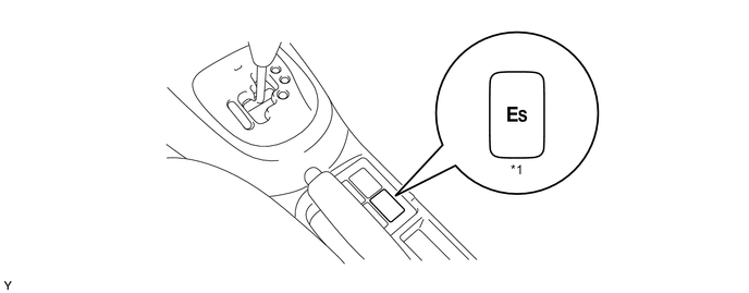
Text in Illustration *1 Pattern Select Switch - -
-
-
Shift Paddle Switch (Transmission Shift Switch Assembly)
-
In M-mode or E-mode, gears can be changed by using the shift paddle switches (transmission shift switch) located behind the steering wheel. Then, the gears change one at a time, as the driver operates the right shift paddle switch (transmission shift switch) (upshift) or the left one (downshift).
-
Individual gears can be selected by entering temporary M-mode through the operation of the shift paddle switches (transmission shift switch) when the shift lever is in E. If specified conditions are met, the system will revert automatically to E-mode.
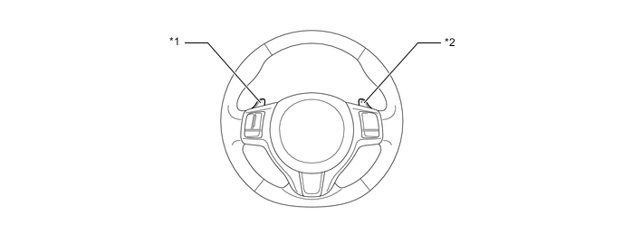
Text in Illustration *1 Shift Paddle Switch (transmission shift switch) ("-" Side) *2 Shift Paddle Switch (transmission shift switch) ("+" Side)
-
-
-
CONSTRUCTION
-
Shift and Select Actuator Assembly
-
The shift and select actuator assembly consists of 2 motors, 2 sensors, and the mechanism listed below. This actuator cannot be disassembled.
-
2 motors (shift and select motors)
-
2 sensors (shift and select stroke sensors)
-
Shift and select mechanism (shift and select lever shaft, shift pinion gear, ring gear, shift actuator plate, select pinion gear and select actuator plate)
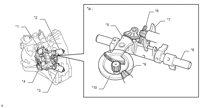
Text in Illustration *1 Shift Stroke Sensor *2 Select Motor *3 Shift Motor *4 Select Stroke Sensor *5 Shift Actuator Plate *6 Select Pinion Gear *7 Select Actuator Plate *8 Shift and Select Lever Shaft *9 Shift Pinion Gear *10 Ring Gear *a Shift and Select Mechanism - - -
-
-
Shift Stroke Sensor and Select Stroke Sensor
-
The shift stroke sensor and select stroke sensor have the same construction and output characteristics.
-
These sensors consist of 2 Hall ICs and a magnetic yoke that rotates in unison with the shift and select lever shaft movement.
-
These sensors convert the changes in the magnetic flux that are caused by the rotation of the shift motor and the select motor (hence, the rotation of the magnetic yoke) into electric signals, and output them to the TCM.
-
The TCM determines the extent of the shift stroke and the select stroke from these electric signals in order to determine the present gear.
-
The main and sub circuits in the shift stroke and the select stroke sensors exhibit the same output characteristics.
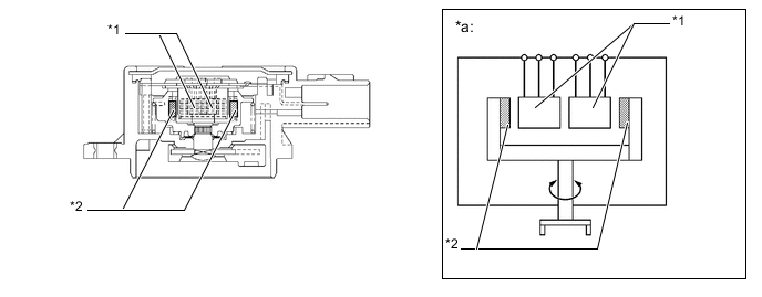
Text in Illustration *1 Hall IC *2 Magnetic Yoke *a Image Diagram - - 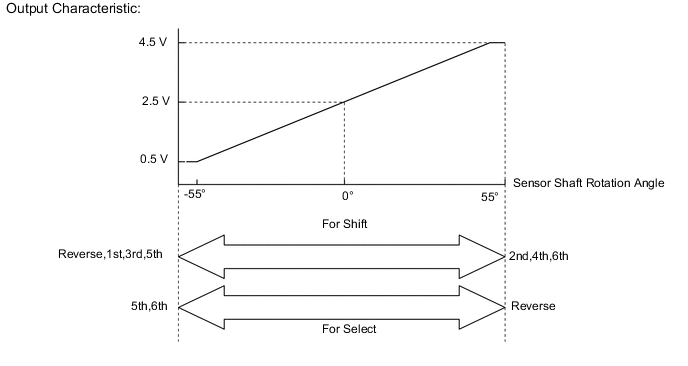
-
-
Clutch Actuator Assembly
-
The clutch actuator assembly consists of the clutch motor, reduction gear, operating rod, reservoir tank, clutch stroke sensor, sensor plate and assist spring. This actuator cannot be disassembled.
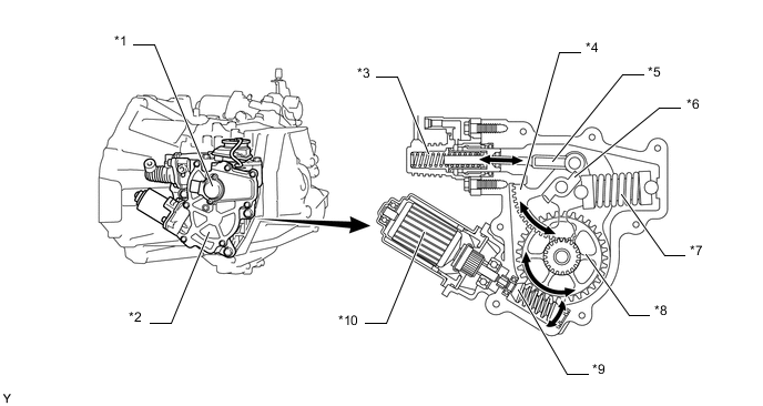
Text in Illustration *1 Clutch Stroke Sensor *2 Clutch Actuator Assembly *3 Clutch Master Cylinder Assembly *4 Reduction Gear *5 Operating Rod *6 Sensor Plate *7 Assist Spring *8 Worm Wheel *9 Worm Shaft *10 Clutch Motor
-
-
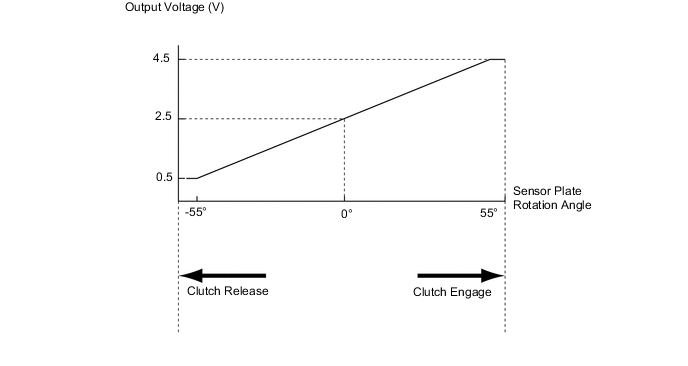
Clutch Stroke Sensor
-
The basic construction and operation of the clutch stroke sensor is the same as for the shift or select stroke sensor. The output voltage characteristics are shown below.
-
-
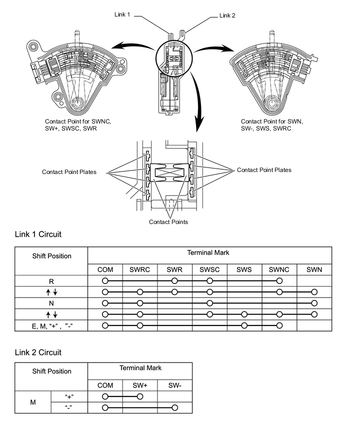
Shift Lever Position Sensor
-
The shift lever position sensor has 2 (link 1 and 2) circuits:
-
The link 1 circuit detects the R, N, E, and M position of the shift lever. This circuit consists of the 6 contact switches.
-
When the shift lever is in M, the link 2 circuit detects the "+" (upshift) or "-" (downshift) signals. This circuit consists of the 2 contact switches.
-
The TCM determines the present shift lever position in accordance with the on/off status of those contact switches.
-
-
-
-
OPERATION
-
Shift and Select Operation
-
When the select motor is actuated, rotary movement is transmitted to the select pinion gear (see A in the illustration below). In sync with the select pinion gear rotation, the select actuator plate moves (see B) to operate the shift and select lever (see C).
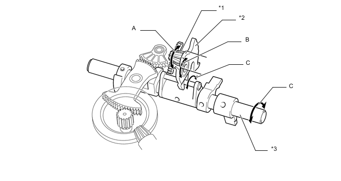
Text in Illustration (Select Operation:) *1 Select Pinion Gear *2 Select Actuator Plate *3 Shift and Select Lever - - -
When the shift motor is actuated, rotary movement is transmitted to the shift pinion gear (see A in the illustration below). And then, the shift pinion gear rotation is transmitted to the ring gear, causing the pinion gear located at the center of the ring gear to rotate (see B). The shift actuator plate is moved by the rotary motion input from the pinion gear (see C), and then the shift and select lever operates (see D).
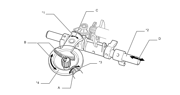
Text in Illustration (Shift Operation:) *1 Shift Actuator Plater *2 Shift and Select Lever *3 Shift Pinion Gear *4 Ring Gear -
These movements are transmitted to the shift fork shaft lever. As a result, the selected gear is changed.
-
-
Clutch Operation
-
The clutch motor operates to pressurize the fluid in the clutch master cylinder assembly, engaging or disengaging the clutch.
-
Rotational movement of the clutch motor is converted to operating rod movement via the worm shaft, worm wheel and reduction gear, pressurizing the fluid in the clutch master cylinder assembly.
-
The fluid pressure of the clutch master cylinder assembly is used to operate the CSC, engaging or disengaging the clutch.
-
When the clutch is being operated, the assist spring provides a force to assist the movement of the operating rod. This reduces the load on the clutch motor at the time the clutch is being released.
-
-
-
FAIL-SAFE
-
Even if a malfunction is detected in the sensors or actuators, the TCM performs fail-safe control to prevent the vehicle driveability from being affected significantly.
-
-
DIAGNOSIS
-
When the TCM detects a malfunction, the TCM makes a diagnosis and memorizes information related to the fault. Furthermore, the M-MT warning light illuminates to inform the driver.
-
The TCM will also store a Diagnostic Trouble Codes (DTCs). The DTCs can be read by connecting the intelligent tester.
-
The DTCs cannot be cleared by merely disconnecting the battery terminals. To clear a DTCs that is stored in the TCM, use the intelligent tester. For details, refer to the Repair Manual.
-