STARTING SYSTEM
-
SYSTEM CONTROL
-
Cranking Hold Function (Models with Entry and Start System but without Tandem Solenoid Starter Assembly)
-
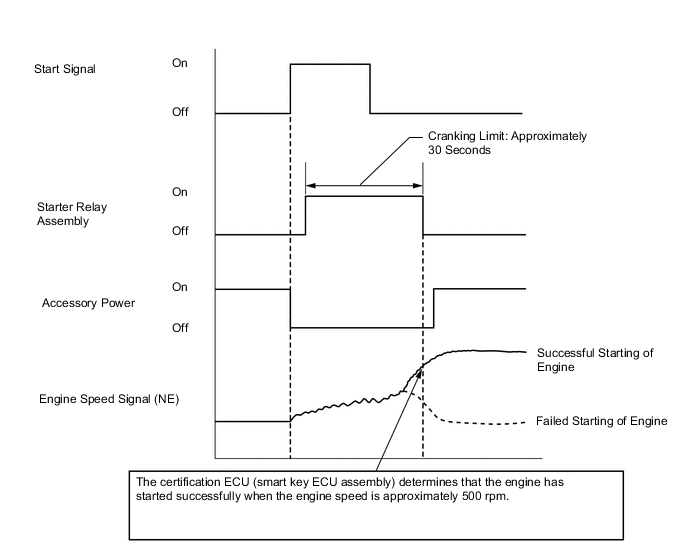
Once the engine switch (push start switch) is pushed, this function continues to operate the starter until the engine starts, provided that the clutch pedal*1 is pressed or park/neutral position switch assembly*2 is closed. This prevents starting failures and the engine from being cranked after the engine has started.
-
This system cuts off the current that powers the accessories while the engine is cranking to prevent the accessory illumination from operating intermittently due to the unstable voltage that is associated with the cranking of the engine.
-
When the certification ECU (smart key ECU assembly) detects a start signal from the engine switch (push start switch), this system monitors the engine speed (NE) signal and continues to operate the starter until it determines that the engine has started. Furthermore, even if the certification ECU (smart key ECU assembly) detects a start signal from the ECM, this system will not operate the starter if the certification ECU (smart key ECU assembly) has determined that the engine has already started.
-
After the starter operates and the engine speed becomes higher than approximately 500 rpm, the certification ECU (smart key ECU assembly) determines that the engine has started and stops the output of the STAR signal to the ST relay. Thus, the starter operation stops and the certification ECU (smart key ECU assembly) energizes the ACC relay.
-
If the engine has any failure and does not start, the starter continues to operate for a predetermined maximum continuous operation time, and stops automatically. The maximum continuous operation time is approximately 30 seconds.
Tech Tips
*1: Models with M/T
*2: Models with CVT
-
-
Cranking Hold Function (Models with both the Entry and Start System and Tandem Solenoid Starter Assembly)
-
Once the engine switch (push start switch) is pushed, this function continues to operate the starter until the engine starts, provided that the park/neutral position switch assembly is closed. This prevents starting failures and the engine from being cranked after the engine has started.
-
This system cuts off the current that powers the accessories while the engine is cranking to prevent the accessory illumination from operating intermittently due to the unstable voltage that is associated with the cranking of the engine.
-
When the certification ECU (smart key ECU assembly) detects a start signal from the engine switch (push start switch), the certification ECU (smart key ECU assembly) turns on the ST relay to move the pinion gear, of the starter, forward. Simultaneously, the certification ECU (smart key ECU assembly) sends a signal to energize the starter motor and starts the engine. This system monitors the engine speed (NE) signal and continues to operate the starter until it determines that the engine has started. Furthermore, even if the certification ECU (smart key ECU assembly) detects a start signal from the ECM, this system will not operate the starter if the certification ECU (smart key ECU assembly) has determined that the engine has already started.
-
After the starter operates and the engine speed becomes higher than approximately 500 rpm, the certification ECU (smart key ECU assembly) determines that the engine has started and stops sending the STAR signal to the ST relay and signal used to energize the starter motor. Thus, the starter operation stops, and the certification ECU (smart key ECU assembly) energizes the ACC relay.
-
If the engine has any failure and does not start, the starter continues to operate for a predetermined maximum continuous operation time, and stops automatically. The maximum continuous operation time is approximately 30 seconds.
-
-
Timing Chart
-
Starting Function (Models with Tandem Solenoid Starter Assembly)
-
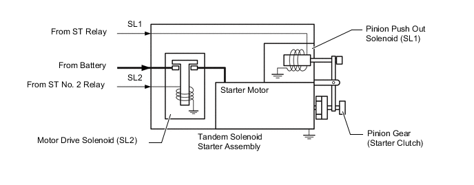
The tandem solenoid starter assembly has a mechanism to separately control the pinion push out solenoid (SL1), which controls the forward movement of the pinion gear (starter clutch), and the motor drive solenoid (SL2), which energizes the starter motor. This allows the pinion gear to engage the ring gear to restart the engine by the stop and start system while the engine is still rotating.
-
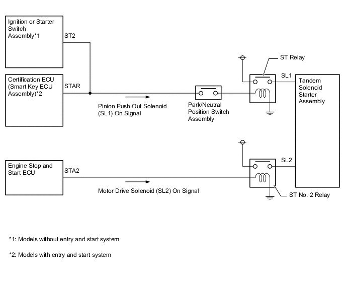
For normal engine start, the ignition or starter switch assembly*1 and certification ECU (smart key ECU assembly)*2 control the pinion push out solenoid (SL1) by sending signals via SL1, and the engine stop and start ECU controls the motor drive solenoid (SL2) by sending signals via SL2.
-
*1: Models without entry and start system
-
*2: Models with entry and start system
-
-
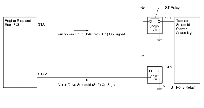
The engine stop and start ECU controls both the pinion push out solenoid (SL1) and motor drive solenoid (SL2) when restarting the engine by the stop and start system.
-
-
-
CONSTRUCTION
-
Armature Coil
-
Instead of round-shaped conductor wires used in a conventional starter assembly, the PS type starter assembly uses square-shaped conductors. In this type of construction, square-shaped conductors can achieve the same magnetic field strength as would be achieved by winding numerous round-shaped conductor wires, but without increasing the mass. As a result, the output torque is increased, and the armature coil is more compact.
-
Because the surface of the square-shaped conductors that are used in the armature coil functions as a commutator, the overall length of the PS type starter assembly is shortened.
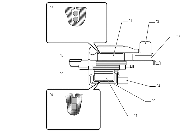
Text in Illustration *1 Starter Armature Assembly *2 Brush *3 Commutator *4 Surface Commutator *a Round-shaped Conductor Wire *b Conventional Type Starter Assembly *c PS Type Starter Assembly *d Square-shaped Conductor
-
-
Field Coil
-
Instead of the field coils used in the conventional starter assembly, the PS type starter assembly used 2 types of permanent magnets: main magnets and interpolar magnets. The main and interpolar magnets are arranged alternately inside the starter yoke assembly. This allows the magnetic flux generated between the main and interpolar magnets to be added to the magnetic flux generated by the main magnets. In addition to increasing the amount of magnetic flux, this construction shortens the overall length of the starter yoke assembly.
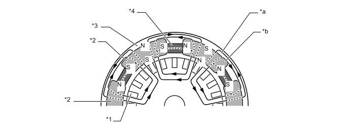
Text in Illustration (Cross Section of Starter Yoke Assembly:) *1 Starter Armature Assembly *2 Main Magnet *3 Starter Yoke Assembly *4 Interpolar Magnet *a Magnetic Flux Generated by Main Magnets. *b Magnetic Flux Generated by Relationship between Main and Interpolar Magnets.
-
-