SPEED LIMITER SYSTEM(for 1KR-FE)
-
FUNCTION OF MAIN COMPONENTS
-
Speed Limiter Control
Component Function Speed Limiter Main Switch Turns on/off the power to the speed limiter control system. Speed Limiter Switch (Cruise Control Main Switch) "CANCEL" A cancel signal can be output to the ECM through the operation of this switch. "+ RES" The acceleration function and resume control function can be performed by operating this switch. A signal is output to the ECM when this switch is operated. "- SET" The deceleration function and set control function can be performed by operating this switch. A signal is output to the ECM when this switch is operated. ECM
-
Controls the speed limiter control mode in accordance with signals from the switches and sensors.
-
If the ECM detects a malfunction in the speed limiter system, it will store a Diagnostic Trouble Code (DTC).
Combination Meter Assembly Speed Limiter Main Indicator Light
-
Based on a speed limiter control indicator operation signal sent by the ECM, the combination meter assembly illuminates the speed limiter main indicator light in green when the speed limiter control mode has been turned on using the speed limiter main switch.
-
Based on a speed limiter control indicator operation signal sent by the ECM, the combination meter assembly illuminates the speed limiter main indicator light in yellow if a malfunction occurs in the speed limiter control mode.
Multi-information Display Shows the state of the speed limiter control mode. Throttle with Motor Body Assembly Throttle Control Motor Adjusts the throttle valve to the limiter position in accordance with signals from the ECM. Throttle Position Sensor Transmits the throttle valve position information to the ECM. Speed Sensor Detects the vehicle speed and transmits a signal via the skid control ECU to the combination meter assembly. Accelerator Pedal Sensor Assembly Detects whether the accelerator pedal is in the kick down mode and transmits signals to the ECM. Clutch Switch Assembly Detects the depressing of the clutch pedal and transmits a signal to the ECM. -
-
-
FUNCTION
Function Outline Constant Speed Control When the speed limiter control is on, the ECM will compare the actual vehicle speed with the limit speed. If the actual vehicle speed is greater than the limit speed, the ECM will control the throttle control motor in the closing direction. Thus, the system reduces the actual vehicle speed to the limit speed. Set Control When the driver turns on the speed limiter main switch, the speed limiter main indicator light will illuminate in the combination meter assembly. In this state, when the speed limiter switch (cruise control main switch) is pressed in the "- SET" direction, the system will memorize the speed that the vehicle was traveling at prior to the operation of the speed limiter switch (cruise control main switch) as a limit speed, and display the limit speed on the combination meter assembly (If the speed limiter switch (cruise control main switch) is pressed in the "- SET" direction while the vehicle is being driven at 30 km/h [20 mph] or less, or while the vehicle is stopped, the system will store the limit speed as being approximately 30 km/h [20 mph]). Coast Control If the driver continues to press the speed limiter switch (cruise control main switch) in the "- SET" direction, the system will reduce the limit speed in 5 km/h or 5 mph increments. The instant the driver releases the speed limiter switch (cruise control main switch), that speed will be stored as the set speed. Tap-down Control If the driver presses the speed limiter switch (cruise control main switch) momentarily (for approximately 0.6 seconds) in the "- SET" direction, the system will reduce the limit speed by 1 km/h or 1 mph with each pressing of the switch. Accelerator Control If the driver continues to press the speed limiter switch (cruise control main switch) in the "+ RES" direction, the system will increase the limit speed in 5 km/h or 5 mph increments. The instant the driver releases the cruise control main switch, that speed will be stored as the limit speed. Tap-up Control If the driver presses the speed limiter switch (cruise control main switch) momentarily (for approximately 0.6 seconds) in the "+ RES" direction, the system will increase the limit speed by 1 km/h or 1 mph with each pressing of the switch. Override Control While driving the vehicle with the speed limiter control on, if the driver fully depresses the accelerator pedal, the ECM will detect that the accelerator pedal sensor assembly is in the kick down mode. Then, the ECM will recognize this to be the driver's acceleration requirement, and allow the vehicle to accelerate higher than the limit speed. After the acceleration, when the vehicle speed falls below the limit speed, this function will resume limit speed control. Cancel Control
-
While the vehicle is being driven with the speed limiter control on, if any one of the following signals is input into the ECM, the system will cancel the speed limiter control:
-
"CANCEL" switch on signal (the driver has pressed the speed limiter switch (cruise control main switch) in the "CANCEL" direction).
-
Speed limiter main switch off signal (deletes the limit speed).
Resume Control After turning the "CANCEL" switch on to turn the speed limiter control off, if the driver pushes the speed limiter switch (cruise control main switch) in the "+ RES" direction, the system will limit the vehicle speed at the limit speed that was set at the time of cancellation. Other Cancellation Items
-
While the clutch pedal is depressed, the system temporarily deactivates the speed limiter control.
-
If the ignition switch is turned off, the limit speed is deleted.
-
-
CONSTRUCTION
-
Speed Limiter Switch (Cruise Control Main Switch)
-
The speed limiter switch (cruise control main switch) consists of the "+ RES", "- SET" and "CANCEL" switches. The "+ RES", "- SET" and "CANCEL" switches are operated using a lever that operates in 3 directions.
-
The speed limiter switch (cruise control main switch) is an automatic reset (normally open) type that turns on only when the switch is being operated and turns off as soon as the driver releases the switch. Furthermore, the functions of the control switch are active only when the speed limiter system has been turned on.
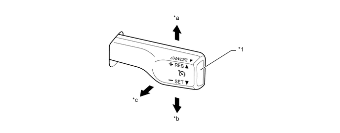
Text in Illustration *1 Speed Limiter Switch (Cruise Control main Switch) - - *a "+ RES" *b "- SET" *c "CANCEL" - -
-
-
-
OPERATION
-
Combination Meter Assembly
-
The combination meter assembly illuminates an indicator light or gives an indication on the multi-information display.
Condition 
Multi-information Display Speed Limiter Main Switch On Illuminates (Green) - Mode Set Effecting Control Illuminates (Green) 
Set Speed Exceeded Illuminates (Green) 

-
The indication comes on and off repeatedly.
Malfunction Occurred Illuminates (Yellow) - -
-
-
-
DIAGNOSIS
-
If a malfunction occurs in the speed limiter system during speed limit control operation, the ECM automatically cancels control and illuminates the speed limiter indicator light in yellow. At this time, the ECM stores the malfunction in the form of a 5-digit Diagnostic Trouble Code (DTC).
-
The 5-digit DTC can be read by connecting the Global TechStream (GTS) to the DLC3. For details, refer to the Repair Manual.
-