INTAKE SYSTEM
-
CONSTRUCTION
-
Air Cleaner
-
A paper type air cleaner filter element sub-assembly is used.
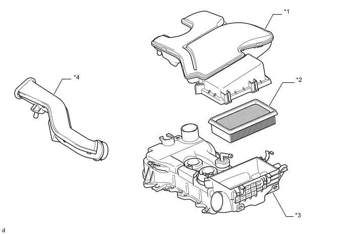
Text in Illustration *1 Air Cleaner Cap Sub-assembly *2 Air Cleaner Filter Element Sub-assembly *3 Cylinder Head Cover Sub-assembly *4 No. 1 Air Cleaner Inlet
-
-
Throttle Body with Motor Assembly
-
A link-less type throttle body with motor assembly in which the throttle control motor and the throttle position sensor are integrated is used. It realizes excellent throttle valve control.
-
In the throttle control motor, a DC motor with excellent response and minimal power consumption is used. The ECM performs the duty ratio control of the direction and the amperage of the current that flows to the throttle control motor in order to regulate the throttle valve angle.
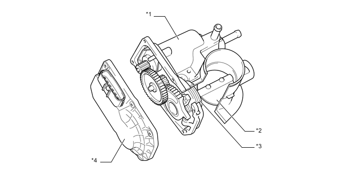
Text in Illustration *1 Throttle Control Motor *2 Throttle Valve *3 Return Spring *4 Throttle Position Sensor
-
-
Intake Manifold
-
The intake manifold has been made of plastic to reduce the weight and the amount of heat transferred from the cylinder head sub-assembly. As a result, it has become possible to reduce the intake air temperature and realize the high intake volumetric efficiency.
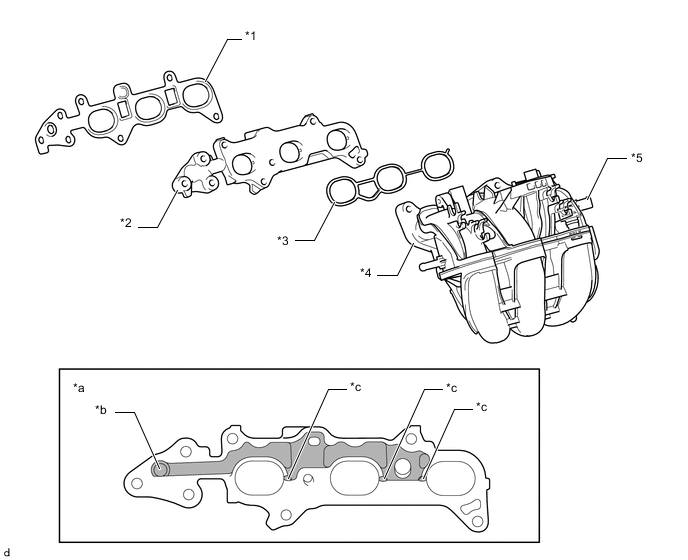
Text in Illustration *1 No. 2 Intake Manifold To Head Gasket *2 No. 1 Intake Manifold Insulator *3 No. 1 Intake Manifold To Head Gasket *4 Intake Manifold *5 E.F.I. Vacuum Sensor Assembly - - *a No. 1 Intake Manifold Insulator Cross Section *b From EGR Valve Assembly *c Through Holes For Exhaust Gas - -
-
-