EMISSION CONTROL SYSTEM
-
FUNCTION OF MAIN COMPONENTS
-
Exhaust Emission Control System
Component Function TWC Reduces emissions by oxidation of CO and HC in exhaust gas and reduction of NOx. Oxygen Sensor Is used to determine the concentration of oxygen remaining in the exhaust gas, and has a characteristic where its output is proportional to the air fuel ratio. No. 2 Oxygen Sensor Detects the oxygen concentration in the exhaust emission by measuring the electromotive force which is generated in the sensor itself. ECM Controls the volume of fuel consumed based primarily on the signal from the oxygen sensor, with minor corrections based on the signal from the No. 2 oxygen sensor. This control optimizes the air fuel ratio. Manifold Temperature Sensor Manifold Pressure Sensor Detects the pressure in the air intake pipe after supercharging. -
Blowby Gas Ventilation System
Component Function Ventilation Valve Sub-assembly Opens and closes the valve using vacuum generated in the air intake pipe and controls the flow rate of the blowby gas. -
Evaporative Emission Control System
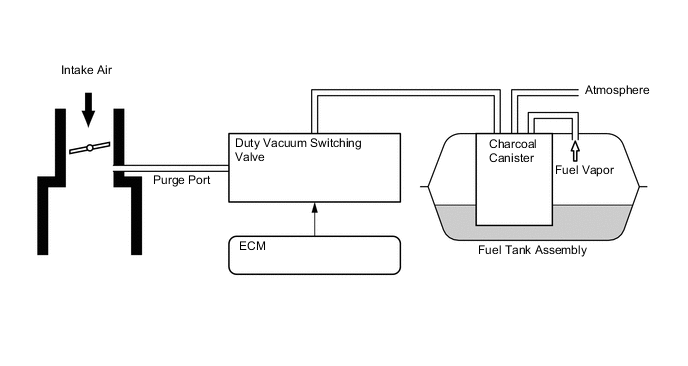
Component Function Fuel Suction Tube Assembly Charcoal Canister Contains activated charcoal to absorb the fuel vapors that are created in the fuel tank assembly. Duty Vacuum Switching Valve Opens and closes the valve based on signals from the ECM and controls the flow rate of the evaporative emission. ECM Controls the duty vacuum switching valve in accordance with the signals from various sensors, in order to achieve a purge volume that suits the driving conditions.
-
-
SYSTEM CONTROL
-
Blowby Gas Ventilation System
-
By introducing blowby gas that has a large amount of HC into the air intake and burning it again, the system attempts to enhance the emission performance. Returning blowby gas volume is regulated to the appropriate amount corresponding to the engine operating conditions, reducing the engine oil volume consumed and engine idling speeds.
-
The ventilation valve sub-assembly passage returns blowby gas into the area after the throttle valve in accordance with the intake vacuum.
-
When load is low, the passage from the cylinder head cover sub-assembly to the area before the throttle valve increases the air purification performance inside the crankcase by introducing fresh air, and when load is high, the passage circulates the blowby gas together with the ventilation valve sub-assembly side passage due to the intake vacuum.
-
An oil separator is located in the cylinder block sub-assembly. This contributes to the compactness of the entire engine.
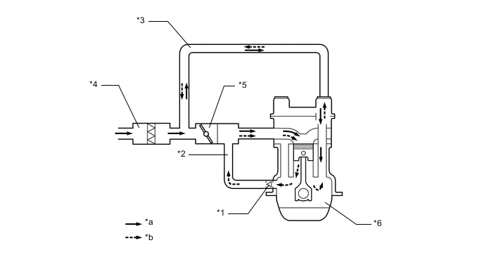
*1 Ventilation Valve Sub-assembly *2 Ventilation Hose *3 No. 2 Ventilation Hose *4 Air Cleaner Assembly *5 Throttle Body with Motor Assembly *6 Crankcase *a Fresh Air *b Blowby Gas
-
-
Evaporative Emission Control System
-
Based on the signals from various sensors, the ECM opens and closes the duty vacuum switching valve. Thus, it controls the purge flow of evaporative emissions (HC) in the charcoal canister in accordance with the engine conditions.
-
-
-
CONSTRUCTION
-
Three-Way Catalytic converter (TWC)
-
A TWC is provided in the front exhaust pipe assembly.
-
The TWC enables improvement of exhaust emissions.
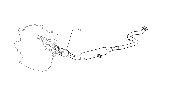
*1 Front Exhaust Pipe Assembly
-
TWC
- - -
-
-