EMISSION CONTROL SYSTEM
-
FUNCTION OF MAIN COMPONENTS
-
The main components of the 1ND-TV emission control system are as follows:
Components Outline Quantity Function Differential Pressure Sensor* Semiconductor Strain Gauge Type 1 This pressure sensor measures the pressure differences between front and back of the DPF catalyst with PM in order to detect the clogging. Exhaust Gas Temperature Sensor* Thermistor Type 2 The exhaust gas temperature sensor is installed in front and back of the oxidation catalyst in order to detect the temperature of the exhaust gas. Air Fuel Ratio Sensor* Wide Band Type with Heater 1 This sensor detects the oxygen concentration in the exhaust gas linearly. Oxidation Catalytic Converter (Exhaust Manifold Converter Sub-assembly) On Exhaust Manifold 1 The converter oxidizes CO and HC in the exhaust gas to purify and then converts them into CO2and H2O, and this has excellent preheating performance as it is provided on the exhaust manifold.
DPF Catalytic Converter (No. 2 Exhaust Manifold Converter Sub-assembly)* On Exhaust Pipe Front 1 This converter traps PM in the exhaust gas and further oxidizes CO and HC to purify and convert them into the CO2and H2O.
EGR Cooler Assembly Water-cooled Type 1 The EGR cooler cools the exhaust gas temperature to improve the EGR efficiency, thus reducing NOX in the exhaust gas. EGR Cooler Bypass Switching Valve VSV Drive Type 1 In response to the engine operating conditions, this valve opens and closes to change the passage through which the EGR gas flows. EGR Valve DC Motor Drive Type 1 This valve opens and closes in accordance with the engine operating conditions and optimally controls the EGR amount. EGR Valve Position Sensor Contact Type 1 This sensor detects the actual amount of the EGR valve opening.
-
*: Models with Diesel Particulate Filter (DPF)
-
-
-
SYSTEM CONTROL
-
System Control Table
-
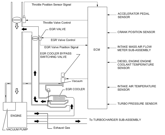
The emission control system of the 1ND-TV engine has the following systems.
System Outline EGR Control Based on the signals received from the sensors, the ECM determines the EGR volume via EGR valve and throttle control valve in accordance with the engine condition. Catalyst Support Control* Based on the signals received from the sensors, the ECM controls the fuel injection from the injector and the engine idle speed to purify PM. Air Fuel Ratio Sensor Heater Control* Maintains the temperature of the air fuel ratio sensors at an appropriate level to increase accuracy of detection of the oxygen concentration in the exhaust gas.
-
*: Models with Diesel Particulate Filter (DPF)
-
-
-
EGR Control
-
This system is designed to reduce and control NOx formation due to a reduction of peak temperature in the engine combustion chamber, which is accomplished by introducing the exhaust gas into intake manifold.
-
By sensing the engine driving conditions and actual amount of the EGR valve opening, the ECM operates the EGR valve and diesel throttle control motor, and regulates the amount of exhaust gas.
-
-
Catalyst Support Control (Models with DPF)
-
The ECM judges the DPF catalyst conditions, based on signals from the air flow meter, engine coolant temperature sensor, 2 exhaust gas temperature sensors, differential pressure sensor and air fuel ratio sensor to control the fuel injection from the injectors and the engine idle speed for the catalyst support control.
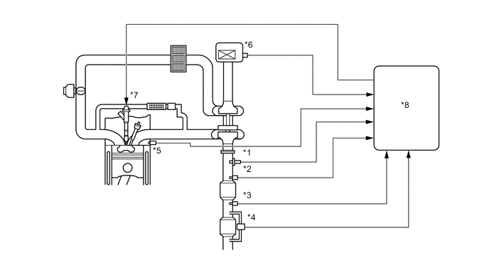
Text in Illustration *1 Air Fuel Ratio Sensor *2 Exhaust Gas Temperature Sensor *3 No. 2 Exhaust Gas Temperature Sensor *4 Differential Pressure Sensor *5 Engine Coolant Temperature Sensor *6 Air Flow Meter *7 Injector *8 ECM -
If the DPF catalyst temperature becomes low, catalyst performance decreases, resulting in an increase of the amount of PM stuck in the filter substrate. When the ECM detects clogs in the filter substrate by calculating the accumulated volume of PM discharged by the engine, a post injection and an idle-up control are performed to reduce PM. At the same time, filter substrate temperature becomes high and PM reacts with active oxygen and changes into CO2for purification. Fuel efficiency drops during this control.
Tech Tips
In the post injection, fuel is injected into the cylinder at a timing at which the fuel is not combusted, sending the fuel into the oxidation catalyst and increasing the exhaust gas temperature by catalytic oxidation reaction, resulting in increasing the catalyst temperature.
-
A small portion of the fuel injected by the post injection enters the crankcase via the cylinder walls, causing dilution of the engine oil. The oil level is less likely to increase during normal use, as the fuel in the oil evaporates with the increase in the engine oil temperature. However, the engine oil is gradually diluted after consecutive driving of which the running distance per single trip is short, which results in reducing the lubricating performance. In an attempt to prevent this, the oil level sensor detects the engine oil level and turns on/blinks the oil change remainder indicator light to urge the driver to change the engine oil.
-
-
-
CONSTRUCTION
-
EGR Cooler
-
A bypass with an EGR cooler bypass switching valve is added to the EGR cooler.
-
If EGR gas is cooled down in the EGR cooler with light engine load, compression air temperature decreases. To prevent this, the EGR gas passage is switched by the EGR cooler bypass switching valve.
Text in Illustration *1 Cooler Core *2 Bypass Passage *3 EGR Cooler Bypass Valve *4 EGR Gas Passage *5 Water Passage - - *a Out (Cooled) *b Out *c In *d A-A Cross Section 
Water 
EGR Gas
-
-
EGR Valve
-
A butterfly type EGR valve, in which the drive is controlled by the DC motor, is used, thus sending a large amount of gas and offering precise control.
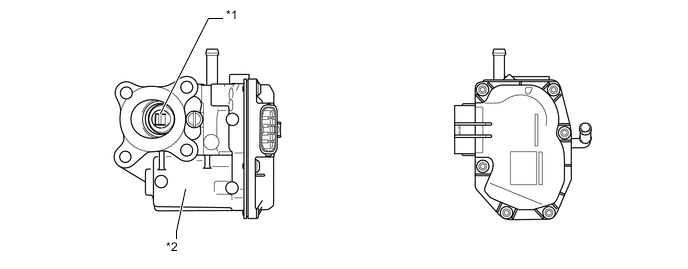
Text in Illustration *1 EGR Valve *2 DC Motor
-
-
Catalytic Converter (Models with DPF)
-
An oxidation catalytic converter (exhaust manifold converter sub-assembly) is used in the exhaust manifold converter.
-
The DPF catalytic converter (No. 2 exhaust manifold converter sub-assembly) is located at the front of the exhaust pipe.
-
The DPF catalyst purifies the PM.
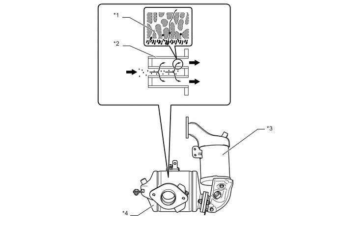
Text in Illustration *1 PM *2 Filter *3 Oxidation Catalytic Converter (Exhaust Manifold Converter Sub-assembly) *4 DPF Catalytic Converter (No. 2 Exhaust Manifold Converter Sub-assembly) Exhaust Gas - -
-
-
Differential Pressure Sensor (Models with DPF)
-
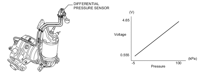
The differential pressure sensor measures the pressure differences between front and back of the DPF catalyst with PM in order to detect the clogging.
-
The sensor is mounted on the cowl, where the effects of vibration are minimal. The DPF catalyst and the sensor are connected with pipes and hoses.
-
-
Exhaust Gas Temperature Sensor and No. 2 Exhaust Gas Temperature Sensor (Models with DPF)
-
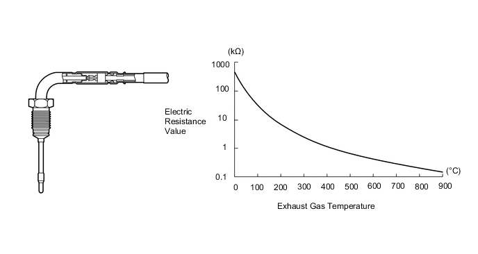
The exhaust gas temperature sensor, which is a thermistor type, is installed in front and back of the oxidation catalytic converter, in order to detect the temperature of the catalyst.
-
-
Air Fuel Ratio Sensor (Models with DPF)
-
The wide band type with heater air fuel ratio sensor is used.
-
This sensor includes a sensor element of zirconia and a heater. The heater is optimally controlled, thus improving the warm-up performance of the sensor.
-
The air fuel ratio sensor and the heated oxygen sensor differ in output characteristics. The air fuel ratio sensor data is approximately proportionate to the existing air fuel ratio. The air fuel ratio sensor converts the oxygen density to the current and sends it to the ECM. The air fuel ratio sensor data is read out by the intelligent tester.
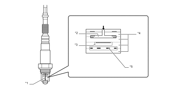
Text in Illustration *1 Sensor Element *2 Diffusion Gap *3 Reference Air *4 Ceramic Foils (ZrO2) *5 Heater - - Exhaust Gas - -
-
-