ENGINE UNIT
-
CONSTRUCTION
-
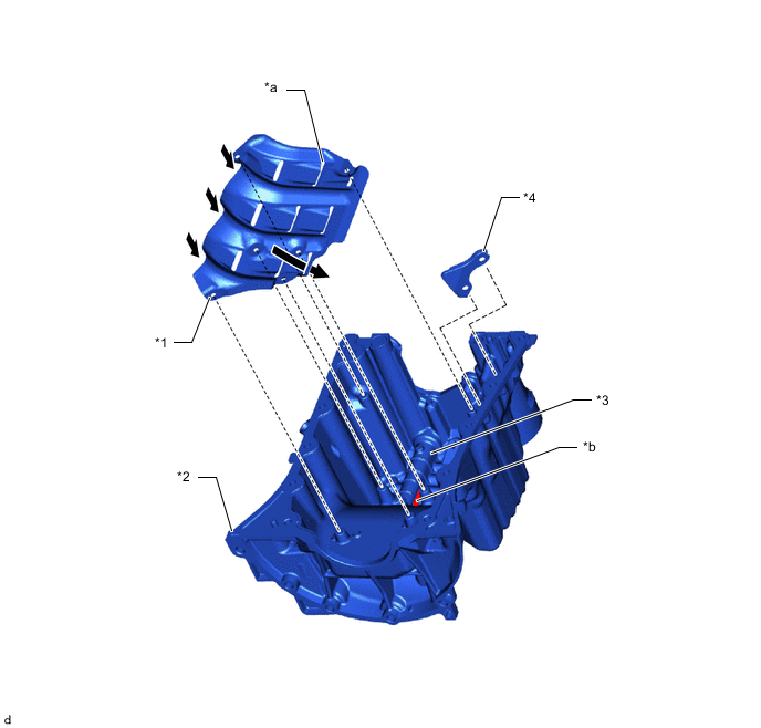
Cylinder Head Cover
-
A plastic cylinder head cover sub-assembly is used for weight reduction.
-
By using a ventilation baffle plate to reduce the blowby gas flow speed, oil droplets and oil mist are eliminated, reducing the amount of oil lost.
-
An oil delivery pipe is installed inside the cylinder head cover sub-assembly. This ensures lubrication of the sliding parts of the roller rocker arms, improving reliability.
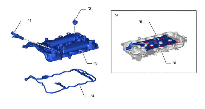
*1 Camshaft Timing Oil Control Valve Assembly *2 Ventilation Valve Sub-assembly *3 Cylinder Head Cover Sub-assembly *4 Cylinder Head Cover Gasket *5 Oil Delivery Pipe *6 Ventilation Baffle Plate *a Back of Cylinder Head Cover Sub-assembly - -
-
-
Cylinder Head
-
A cylinder head sub-assembly made of aluminum alloy is used.
-
The cylinder head sub-assembly structure has been simplified by separating the camshaft housing sub-assembly (cam journal portion) from the cylinder head sub-assembly.
-
The cylinder head gasket adopts a metal, 2-tier type equipped with a shim around the cylinder bore. By adopting a shim, the width of the seal surface of the cylinder bore is increased to ensure the gas seal and durability.
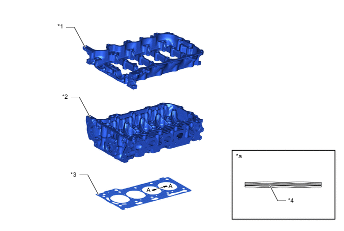
*1 Camshaft Housing Sub-assembly *2 Cylinder Head Sub-assembly *3 Cylinder Head Gasket *4 Shim *a A-A Cross Section - - -
The angle of the intake and exhaust valves has been narrowed and set at 23.3° to permit a compact cylinder head sub-assembly.
-
The cylinder head sub-assembly contains a pentroof type combustion chamber. The spark plug is located in the center of the combustion chamber in order to improve the engine's anti-knocking performance.
-
Needle-needle type spark plugs with a 12 mm (0.472 in.) diameter threaded base are used in order to make it possible to increase the diameter of the intake and exhaust valves. As a result, improved intake and exhaust efficiency has been achieved.
-
A taper squish combustion chamber is used to improve anti-knocking performance and intake efficiency. In addition, engine performance and fuel economy have been improved.
-
Siamese type intake ports are used to reduce the overall surface area of the intake port walls. This helps prevent fuel from adhering to the intake port walls, thus reducing HC exhaust emissions.
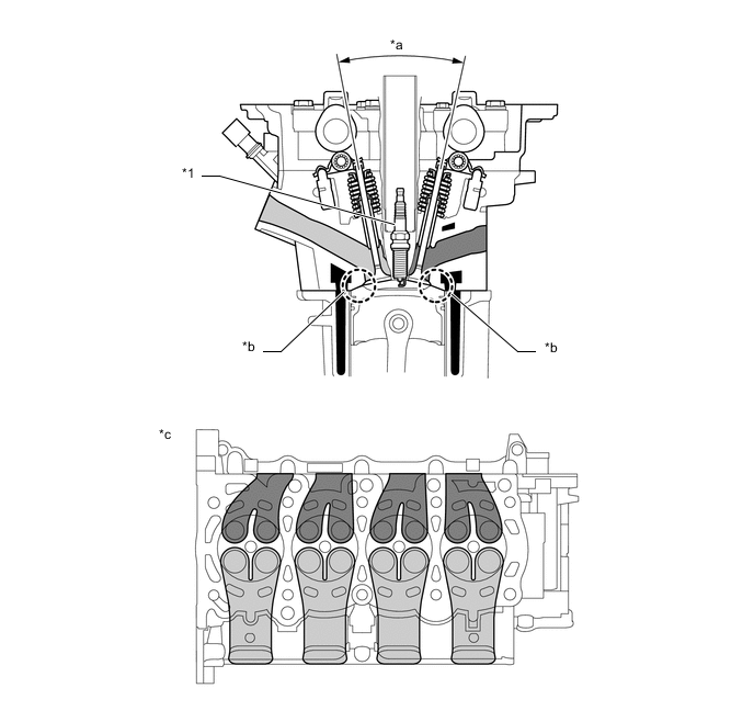
*1 Spark Plug - - *a 23.3° *b Taper Squish *c Cylinder Head Sub-assembly Bottom View - - 
Water Jacket 
Exhaust Port 
Intake Port - -
-
-
Cylinder Block
-
An aluminum cylinder block sub-assembly with a 7 mm (0.276 in.) distance between the cylinder bores is used to achieve a compact and lightweight configuration.
-
The cylinder bores are heat treated to prevent wear, reducing oil consumption.
-
A spiny type liner, which has an irregularly shaped outer casting surface, is used to enhance the adhesion between the liners and the aluminum of the cylinder block sub-assembly. The enhanced adhesion helps heat dissipation, resulting in a lower overall temperature and reduced heat deformation of the cylinder bores. A cylinder block sub-assembly with this type of liner cannot be rebored.
-
Plateau honing is used for the cylinder bores. This precision finish replicates a broken-in bore surface, minimizing friction. Water-soluble coolant is used for the plateau honing in consideration of the environment.
-
An open deck type water jacket is used. By optimizing the bore wall thickness, water jacket depth and outer wall ribs, cooling performance is enhanced.
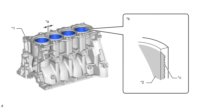
*1 Cylinder Block Sub-assembly *2 Cylinder Liner *a 7 mm (0.276 in.) *b Cylinder Bore Cross Section *c Irregularly Shaped Outer Casting Surface of Liner (Spiny Type Liner) - - -
Water passages are provided between the cylinder bores. By allowing the engine coolant to flow between the cylinder bores, this construction enables the temperature of the cylinder walls to be kept uniform.
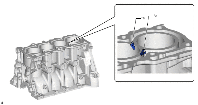
*a Water Passage - -
-
-
Water Jacket Spacer
-
Resin cylinder block water jacket spacers with foam rubber liners are used inside the water jackets of the cylinder block sub-assembly.
-
The cylinder block water jacket spacers optimize the flow of coolant within the water jackets. The resin cylinder block water jacket spacer is held tightly to the cylinder bores by springs, keeping the temperature of the cylinder bore walls uniform. As a result, deformation due to temperature differences across the cylinder bores is suppressed, reducing friction between the pistons and bores.
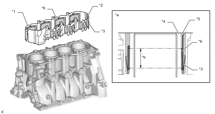
*1 No. 1 Cylinder Block Water Jacket Spacer *2 No. 2 Cylinder Block Water Jacket Spacer *3 Spring *4 Cylinder Bore *5 Water Jacket *6 Foam Rubber *a Cylinder Bore Cross Section *b Temperature is kept even by foam rubber.
-
-
Cam Drive Control
-
A timing chain (chain sub-assembly) with an 8 mm (0.315 in.) pitch is used to make the engine more compact.
-
The No. 1 chain tensioner assembly uses a spring and oil pressure to maintain proper chain tension at all times.
-
The No. 1 chain tensioner assembly suppresses noise generated by the timing chain (chain sub-assembly).
-
The No. 1 chain tensioner assembly is a ratchet type tensioner with a non-return mechanism.
-
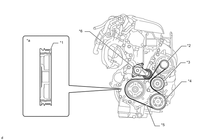
An aluminum die-cast timing chain cover assembly is used.
-
The timing chain cover assembly has an integrated construction including parts of the cooling system (water pump and water passage) and the lubrication system (oil pump and oil passage). Thus, the number of parts has been reduced for weight reduction.
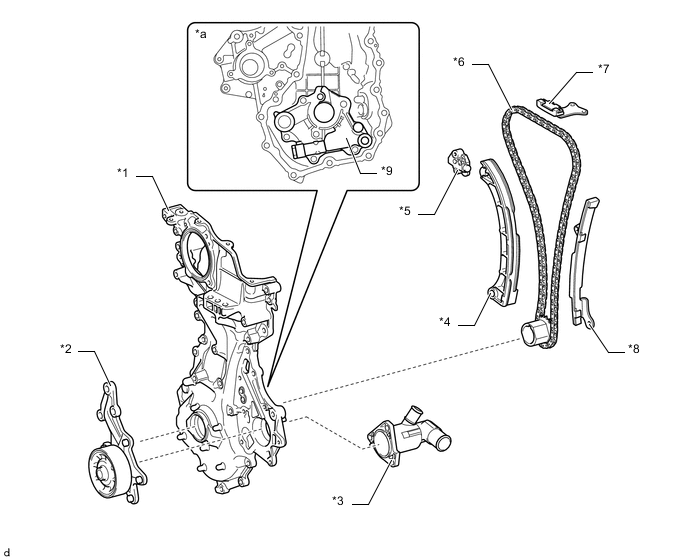
*1 Timing Chain Cover Assembly *2 Engine Water Pump Assembly *3 Water Inlet with Thermostat Sub-assembly *4 Timing Chain Tension Arm *5 No. 1 Chain Tensioner Assembly *6 Timing Chain (Chain Sub-assembly) *7 No. 2 Chain Vibration Damper *8 Timing Chain Guide *9 Oil Pump Cover - - *a Back of Timing Chain Cover Assembly - -
-
-
Valve Mechanism
-
This engine has a dual Variable Valve Timing-intelligent (VVT-iE and VVT-i) system which controls the intake and exhaust camshafts to provide optimal valve timing according to driving conditions. With this adoption, lower fuel consumption, higher engine performance, and fewer exhaust emissions have been achieved.
-
Cast iron camshafts are used.
-
The No. 1 valve rocker arm sub-assembly is used as a valve mechanism and by achieving size reduction while drastically reducing the amount of friction that occurs between the sliding parts and cams, low fuel consumption is achieved. Also, a hydraulic valve lash adjuster assembly is used to make valve clearance adjustment unnecessary in consideration of serviceability.
-
Together with the use of the No. 1 valve rocker arm sub-assembly, the cam profile has been designed with a concave R (radius). This results in increased valve lift when the valve begins to open and finishes closing, helping to achieve enhanced output performance.
-
A valve spring (outer compression spring), whose upper portion is shaped like a beehive, is used to reduce inertial mass. As a result, the load on the valve spring (outer compression spring) and friction are reduced.
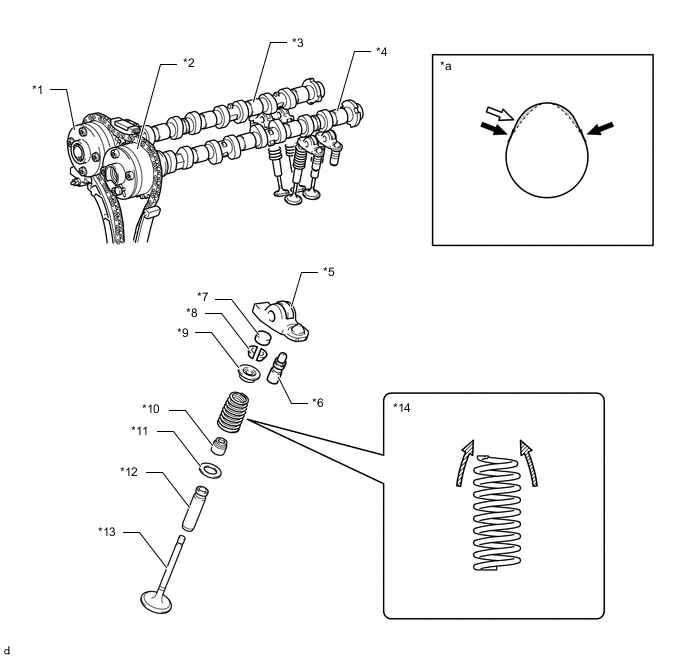
*1 Camshaft Timing Gear Assembly *2 Camshaft Timing Exhaust Gear Assembly *3 Intake Camshaft (Camshaft) *4 Exhaust Camshaft (No. 2 Camshaft) *5 No. 1 Valve Rocker Arm Sub-assembly *6 Valve Lash Adjuster Assembly *7 Valve Stem Cap *8 Valve Spring Retainer Lock *9 Valve Spring Retainer *10 Oil Seal *11 Valve Spring Sheet *12 Valve Guide Bush *13 Valve *14 Valve Spring (Outer Compression Spring) *a Cam Profile - - 
Cam with Concave R 
Concave R Portion of Cam (Profile) 
Beehive - - Lift Amount Increase - - Figure 1. Valve Timing
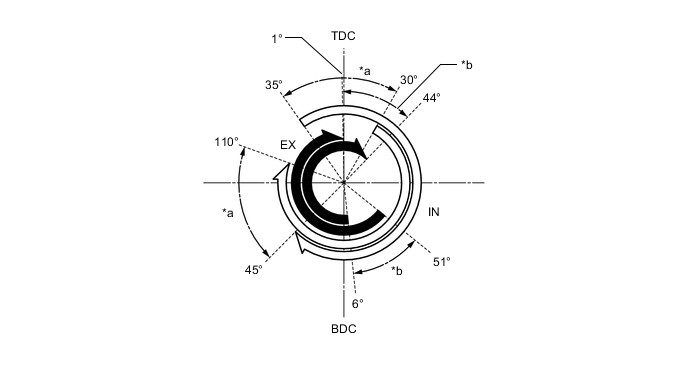
*a Intake VVT-iE Operation Range *b Exhaust VVT-i Operation Range Exhaust Valve Opening Angle Intake Valve Opening Angle
-
-
Valve Rocker Arm
-
The valve mechanism uses a No. 1 valve rocker arm sub-assembly with built-in needle bearings. This reduces the friction that occurs between the cams and the areas on the No. 1 valve rocker arm sub-assemblies that push the valves down, thus improving fuel economy.
*1 Valve Lash Adjuster Assembly *2 No. 1 Valve Rocker Arm Sub-assembly *3 Needle Bearing - -
-
-
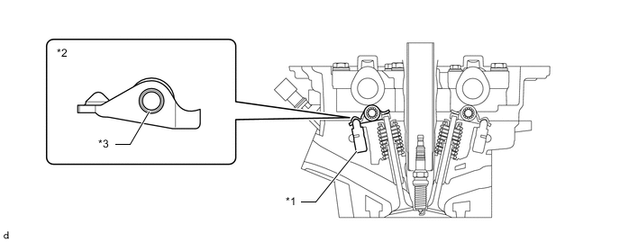
Valve Lash Adjuster
-
A valve lash adjuster assembly is located at the fulcrum of each No. 1 valve rocker arm sub-assembly. A valve lash adjuster assembly consists primarily of a plunger, a plunger spring, a check ball and a check ball spring.
-
The valve lash adjuster assembly is actuated by the engine oil, plunger spring and check ball spring. The oil pressure and the spring force that act on the plunger push the No. 1 valve rocker arm sub-assembly against the cam, in order to adjust the valve clearance. This reduces the engine noise that is created during the opening and closing of the valve.
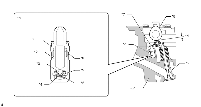
*1 Body *2 Plunger *3 Check Ball *4 Ball Retainer *5 Check Ball Spring *6 Plunger Spring *7 No. 1 Valve Rocker Arm Sub-assembly *8 Cam *9 Valve *10 Cylinder Head Sub-assembly *a Valve Lash Adjuster Assembly Cross Section *b Oil Hole *c Oil Passage *d Clearance
-
-
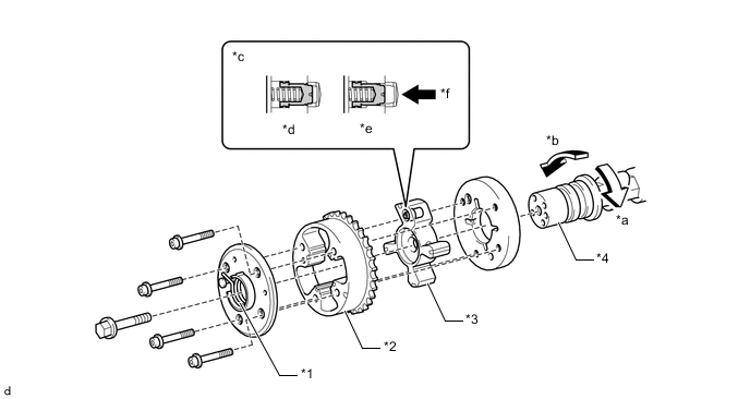
Camshaft Control Actuator
-
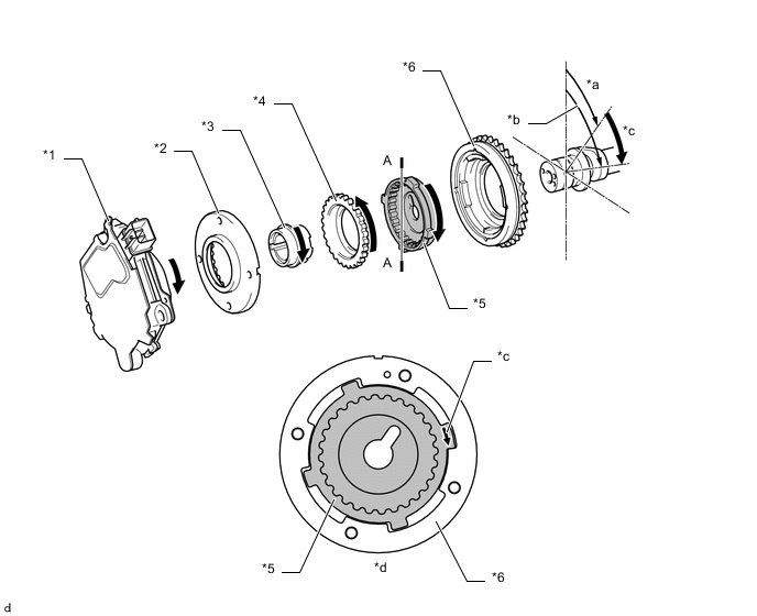
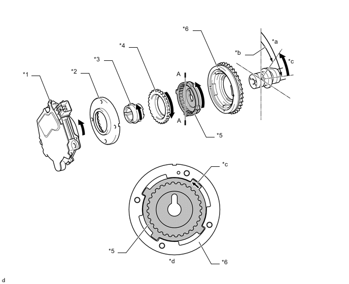
The camshaft control actuator (camshaft timing gear assembly) rotates the intake camshaft to the advance side or retard side, and consists of a 2-stage cycloid reduction unit which reduces the rotation speed of the cam timing control motor with EDU assembly.
-
The rotation of the cam timing control motor with EDU assembly rotates the planetary gear via the cycloid reduction unit. By rotating the planetary gear, the intake camshaft fixed into the camshaft gear is rotated to the advance side or retard side.
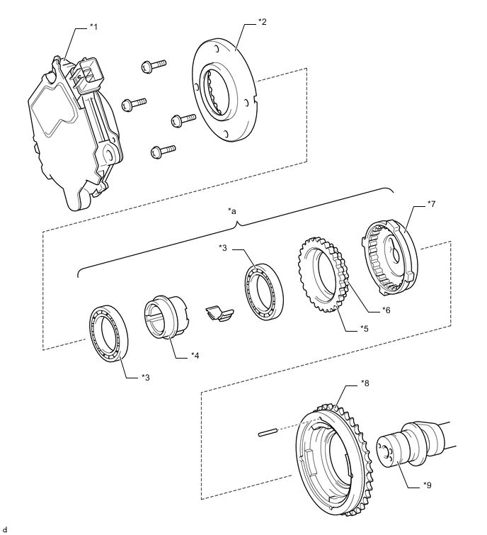
*1 Cam Timing Control Motor with EDU Assembly *2 Sprocket Gear *3 Bearing *4 Eccentric Shaft *5 Planetary Gear
-
Large Gear
*6 Planetary Gear
-
Small Gear
*7 Camshaft Gear (Fixed on Intake Camshaft) *8 Cam Sprocket *9 Intake Camshaft - - *a Cycloid Reduction Unit - - -
-
-
VVT-i controller
-
A 4-blade vane type VVT-i controller (camshaft timing exhaust gear assembly) is used on the exhaust side.
-
When the engine is stopped, a lock pin locks the exhaust camshaft at the most advanced position to ensure that the engine starts properly.
-
An advance assist spring is provided in the camshaft timing exhaust gear assembly to assist the necessary torque in the advanced direction to keep the lock pin securely connected when the engine is stopped.
-
The ECM controls the amount of oil pressure applied to the advanced chamber and retarded chamber inside the camshaft timing exhaust gear assembly based on signals from each sensor via the camshaft timing oil control valve assembly installed on the cylinder head cover sub-assembly and continuously changes the exhaust camshaft (No. 2 camshaft) phase.
*1 Advance Assist Spring *2 Housing *3 Vane (Fixed on Exhaust Camshaft (No. 2 Camshaft)) *4 Exhaust Camshaft (No. 2 Camshaft) *a Advance *b Retard *c Lock Pin Operating *d At a Stop *e In Operation *f Oil Pressure
-
-
Piston
-
Pistons made of lightweight aluminum alloy are used, with a taper squish shape upper surface for highly efficient intake and combustion, and a shape to maintain tumble flow.
-
A surface treatment with superior seize resistance is used with a resin coating for the piston skirts to ensure scuffing resistance and low friction.
-
Low-tension piston rings are used to reduce friction and achieve excellent fuel economy.
-
The sliding surface of the No. 1 compression ring uses a Diamond Like Carbon (DLC) coating, providing low friction and high wear resistance, while the top and bottom surfaces have received nitride treatment for improved wear resistance.
-
The sliding surface of the No. 2 compression ring is chrome plated for improved wear resistance.
-
The oil ring uses a 3-piece type for improved reliability and reduced tension, while a DLC coating on the sliding surface provides reduced friction and improved abrasion resistance.
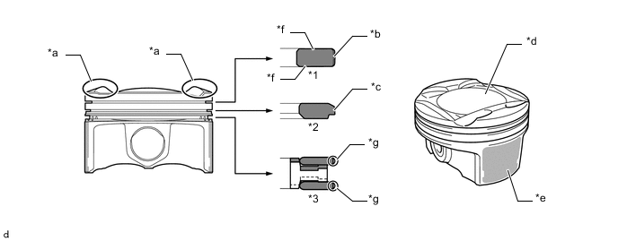
*1 No. 1 Compression Ring *2 No. 2 Compression Ring *3 Oil Ring - - *a Taper Squish Shape *b DLC Coating *c Chrome Plating *d Tumble Flow Maintaining Shape *e Resin Coating *f Nitride Treatment *g DLC Coating (Top and Bottom Asymmetry Barrel) - -
-
-
Connecting Rod and Connecting Rod Bearing
-
The connecting rod sub-assemblies are made of high-strength steel for weight reduction.
-
Plastic region tightening bolts (connecting rod bolts) are used to achieve light weight.
-
The lining surface of the connecting rod bearing is micro-grooved to provide an optimal oil clearance. As a result, cold-engine cranking performance has been improved and engine vibration has been reduced.
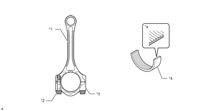
*1 Connecting Rod *2 Plastic Region Tightening Bolt (Connecting Rod Bolt) *3 Connecting Rod Cap *4 Connecting Rod Bearing *a Micro-grooved - -
-
-
Crankshaft
-
A crankshaft made of forged steel, which excels in rigidity and wear resistance, is used.
-
The crankshaft has 5 main journals and 8 balance weights.
-
The oil groove on the crankshaft bearing is made eccentric to reduce the amount of oil leakage from the bearing. This enables the capacity of the oil pump to be reduced in order to reduce parasitic losses.
-
Resin coated aluminum crankshaft bearings are used for the crankshaft bearings. The crankshaft bearings are reduced in width to reduce friction.
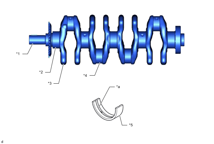
*1 Crankshaft *2 Crank Journal *3 Balance Weight *4 Crank Pin *5 Crankshaft Bearing - - *a Oil Groove - -
-
-
Oil Pan
-
A lightweight aluminum alloy oil pan sub-assembly is used. By integrating the stiffener into the oil pan sub-assembly, the rigidity of the joint between the oil pan sub-assembly and the continuously variable transaxle assembly is enhanced.
-
The oil strainer is integrated into the oil pan sub-assembly to reduce the number of parts and weight.
-
The shape of the oil strainer inlet port is optimized to ensure a high rate of oil flow, enhancing reliability.
-
The No. 1 oil pan baffle plate contains curved shaped, optimally positioned oil traps to remove air from the oil.
-
The No. 2 oil pan baffle plate prevents oil mist in the crankcase from entering the blowby gas passages, enhancing reliability.
*1 No. 1 Oil Pan Baffle Plate *2 Oil Pan Sub-assembly *3 Oil Strainer *4 No. 2 Oil Pan Baffle Plate *a Oil Trap *b Oil Strainer Inlet Port Oil Flow - -
-
-
V-ribbed Belt
-
Accessory components are driven by a serpentine belt consisting of a single fan and generator V belt. This reduces the overall engine length, weight and the number of engine parts.
-
An automatic V-ribbed belt tensioner assembly eliminates the need for tension adjustment.
-
The crankshaft pulley contains torsional damper rubber to reduce torsional vibration of the crankshaft.
*1 Torsional Damper Rubber *2 Generator with Clutch Pulley *3 Water Pump Pulley *4 Cooler Compressor Pulley *5 Fan and Generator V Belt *6 V-ribbed Belt Tensioner Assembly *a Crankshaft Pulley Cross Section - -
-
-
Engine Mount
-
The engine is supported by 3 mountings. A hydraulic mounting is used for the engine mounting insulator sub-assembly RH to reduce vibration and noise.
Figure 2. Models with CVT
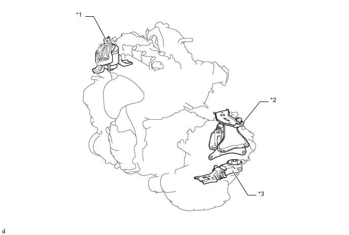
*1 Engine Mounting Insulator Sub-assembly RH *2 Engine Mounting Insulator LH *3 Engine Moving Control Rod - - Figure 3. Models with Manual Transaxle
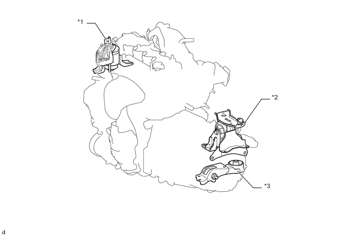
*1 Engine Mounting Insulator Sub-assembly RH *2 Engine Mounting Insulator LH *3 Engine Moving Control Rod - -
-
-
-
OPERATION
-
Camshaft Control Actuator
-
Cycloid Reduction Unit
-
The cycloid reduction unit consists of a sprocket gear, an eccentric shaft, a planetary gear and a camshaft gear.
-
The eccentric shaft has a circular shape, which is eccentric in relation to the rotation axis of the camshaft, and connects with the sprocket gear.
-
The sprocket gear has 1 tooth more than the large gear of the planetary gear, and the small gear of the planetary gear has 1 tooth less than the camshaft gear.
-
Through the eccentric movement of the eccentric shaft, the planetary gear rotates while meshing with the sprocket gear and camshaft gear.
-
When the eccentric shaft rotates once, the planetary gear moves while meshing with the sprocket gear, and rotates by 1 tooth only. The rotations that are decelerated by the cycloid reduction unit cause the intake camshaft to rotate.
*1 Sprocket Gear *2 Eccentric Shaft *3 Planetary Gear
-
Large Gear
*4 Camshaft Gear *5 Planetary Gear
-
Small Gear
- - *a Eccentric shaft rotates 120° *b Eccentric shaft rotates 240° *c Eccentric shaft rotates 360° *d Rotates by 1 tooth of planetary gear -
-
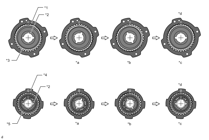
Advance Operation
-
As the advance signals from the ECM cause the motor to rotate faster than the camshaft, the camshaft gear rotates in the direction shown in the illustration via the reduction unit. This rotation causes the intake camshaft coupled with the camshaft gear to rotate in the advance direction.
*1 Cam Timing Control Motor with EDU Assembly *2 Sprocket Gear *3 Eccentric Shaft *4 Planetary Gear *5 Camshaft Gear (Fixed on Intake Camshaft) *6 Cam Sprocket *a Sprocket Speed *b Camshaft Speed *c Advance Side *d A-A Cross Section -
-
Retard Operation
-
As the retard signals from the ECM cause the motor to rotate slower than the camshaft, the camshaft gear rotates in the direction shown in the illustration via the reduction unit. This rotation causes the intake camshaft coupled with the camshaft gear to rotate in the retard direction. The motor turns clockwise and counterclockwise in accordance with engine conditions.
*1 Cam Timing Control Motor with EDU Assembly *2 Sprocket Gear *3 Eccentric Shaft *4 Planetary Gear *5 Camshaft Gear (Fixed on Intake Camshaft) *6 Cam Sprocket *a Sprocket Speed *b Camshaft Speed *c Retard Side *d A-A Cross Section -
-
Hold Operation
-
After the target valve timing has been reached, the ECM rotates the motor at the same rotational speed as the camshaft. As a result, the camshaft control actuator becomes locked, thus holding the camshaft at the valve timing.
-
-
-
VVT-i controller
-
Advance
-
When the camshaft timing oil control valve assembly is operated as illustrated below by the advance signal from the ECM, the resultant oil pressure is applied to the timing advance side vane chamber to rotate the camshaft in the timing advance direction.
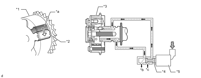
*1 Housing *2 Vane (Fixed on Exhaust Camshaft (No. 2 Camshaft)) *3 Camshaft Timing Exhaust Gear Assembly *4 Spool Valve *5 Camshaft Timing Oil Control Valve Assembly - - *a Advance Side Vane Chamber *b Drain *c From Oil Pump - - Oil Pressure Rotation Direction From ECM - - -
-
Retard
-
When the camshaft timing oil control valve assembly is operated as illustrated below by the retard signal from the ECM, the resultant oil pressure is applied to the timing retard side vane chamber to rotate the camshaft in the timing retard direction.
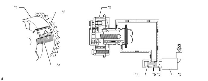
*1 Housing *2 Vane (Fixed on Exhaust Camshaft (No. 2 Camshaft)) *3 Camshaft Timing Exhaust Gear Assembly *4 Spool Valve *5 Camshaft Timing Oil Control Valve Assembly - - *a Retard Side Vane Chamber *b From Oil Pump *c Drain - - Oil Pressure Rotation Direction From ECM - - -
-
Hold
-
After reaching the target timing, the valve timing is held by keeping the camshaft timing oil control valve assembly in the neutral position unless the traveling state changes. This adjusts the valve timing at the desired target position and prevents the engine oil from running out when it is unnecessary.
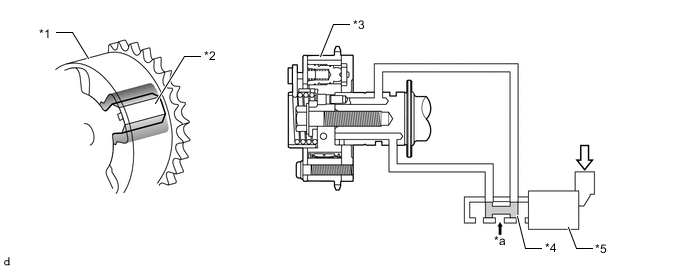
*1 Housing *2 Vane (Fixed on Exhaust Camshaft (No. 2 Camshaft)) *3 Camshaft Timing Exhaust Gear Assembly *4 Spool Valve *5 Camshaft Timing Oil Control Valve Assembly - - *a From Oil Pump - - Oil Pressure From ECM -
-
-
Crankshaft
-
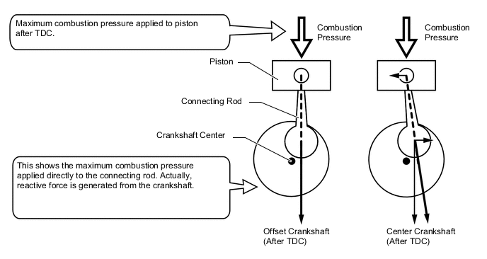
Through the use of an offset crankshaft, the centerline of the cylinder bores is shifted 8 mm (0.315 in.) towards the exhaust in relation to the centerline of the crankshaft. Thus, the side force (thrust) applied to the cylinder walls is reduced when maximum combustion pressure is applied. This contributes to fuel economy.
-
Maximum combustion pressure is efficiently transmitted to the crankshaft, and the thrust direction force applied to the pistons in the combustion stroke is reduced thereby reducing friction loss.
-
-