ENGINE UNIT
-
CONSTRUCTION
-
Cylinder Head Cover Sub-assembly (Models with DPF)
-
A cylinder head cover sub-assembly made of lightweight plastic resin is used.
-
The cylinder head cover sub-assembly includes an oil delivery pipe, and by supplying oil, ensures that the sliding portions of the valves are properly lubricated, leading to improved reliability.
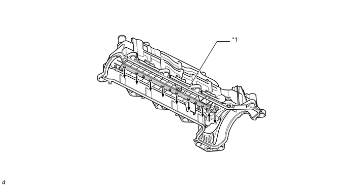
Text in Illustration *1 Oil Delivery Pipe - - 
Oil - -
-
-
Cylinder Head Sub-assembly
-
The cylinder head sub-assembly is made of aluminum alloy.
-
The intake manifold is integrated the cylinder head sub-assembly to realize compact design.
-
The injector is located near the center of the combustion chamber to promote the mixture of fuel and air.
-
A water jacket consists of the 2-stage construction to realize excellent cooling performance.
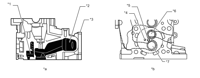
Text in Illustration *1 Water Jacket *2 Intake Manifold *3 Cylinder Head Sub-assembly *4 Glow Plug Hole *5 Injector Hole *6 Exhaust Valve *7 Intake Valve - - *a Cylinder Head Sub-assembly Cross Section *b View from the Bottom
-
-
Cylinder Block Sub-assembly
-
The cylinder block sub-assembly is made of aluminum die-cast.
-
A compact block has been achieved by producing the thin cast-iron liners and cylinder block sub-assembly as a unit. Do not bore the block with this liner.
-
The liners are the spiny-type, which have been manufactured so that their casting exterior forms a large irregular surface in order to enhance the adhesion between the liners and the aluminum cylinder block sub-assembly. The enhanced adhesion helps improve heat dissipation, resulting in a lower overall temperature and heat deformation of the cylinder bores.
-
Cylinder block water jacket spacers are used in the water jackets of the cylinder block sub-assembly. They suppress the water flow in the center of the water jackets, guide the coolant above and below the cylinder bores, and ensure uniform temperature distribution. As a result, the viscosity of the engine oil that acts as a lubricant between the bore walls and the pistons can be lowered, thus reducing friction.
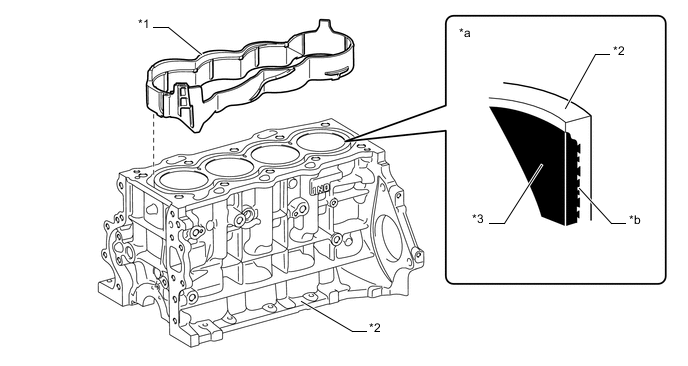
Text in Illustration *1 Cylinder Block Water Jacket Spacer *2 Cylinder Block Sub-assembly *3 Spiny Type Liner - - *a Cylinder Bore Cross Section *b Irregularly Shaped Outer Casting Surface of Liner
-
-
Oil Pan Sub-assembly
-
The oil pan sub-assembly is made of aluminum die-cast.
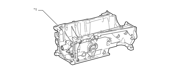
Text in Illustration *1 Oil Pan Sub-assembly - -
-
-
Piston (Models without DPF)
-
The pistons are made of aluminum alloy.
-
The combustion chamber is provided on the piston for direct injection.
-
A cooling channel is provided to realize excellent piston cooling performance.
-
A cast iron ring carrier is used to realize excellent wear resistance.
-
The piston skirt is coated with resin to reduce friction.
-
Full floating type piston pins are used.
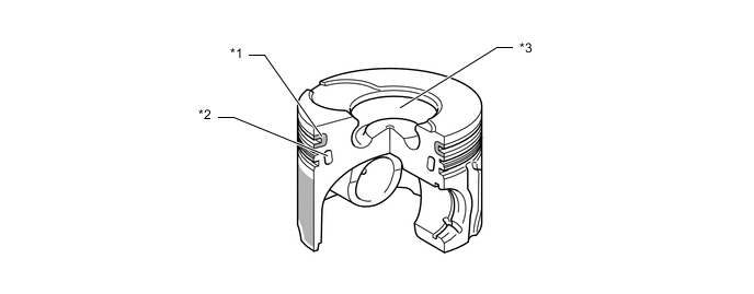
Text in Illustration *1 No. 1 Journal Cast Iron Ring Carrier *2 Cooling Channel *3 Combustion Chamber - - 
Resin Coating - -
-
-
Piston (Models with DPF)
-
The pistons are made of aluminum alloy.
-
By optimizing the squish area at the top of the piston head, the flow of intake air and fuel is controlled, realizing increased cooling efficiency of the area around the combustion chamber.
-
The combustion chamber bowl has been offset from the center to optimize the flow of the fuel air mixture, suppressing the generation of white smoke while at the same time realizing increased fuel efficiency.
-
A cooling channel is provided to realize excellent piston cooling performance.
-
A cast iron ring carrier is used to realize excellent wear resistance.
-
The piston skirt is coated with resin to reduce friction.
-
The piston pin has been provided with a Diamond Like Carbon (DLC) coating to reduce friction.
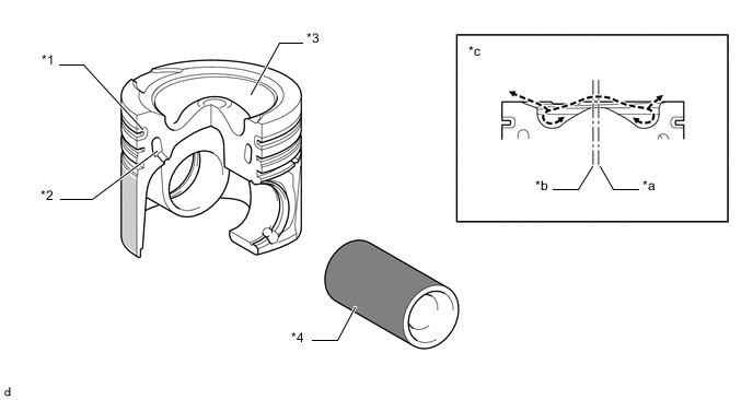
Text in Illustration *1 No. 1 Journal Cast Iron Ring Carrier *2 Cooling Channel *3 Combustion Chamber *4 Piston Pin *a Combustion Chamber Center *b Bore Center *c Cross Section - - Flow of Fuel Air Mixture - - 
Diamond Like Carbon (DLC) Coating Resin Coating
-
-
Connecting Rod Sub-assembly
-
The connecting rod sub-assemblies and caps are made of high strength steel for weight reduction.
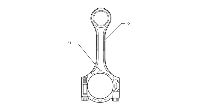
Text in Illustration *1 Front Mark *2 Connecting Rod Sub-assembly
-
-
Crankshaft
-
The crankshaft has 5 journals and 4 balance weights.
-
The crankshaft is made of forged steel.
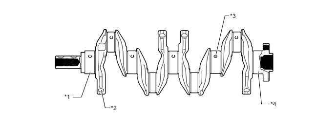
Text in Illustration *1 No. 1 Journal *2 Balance Weight *3 Oil Hole *4 No. 5 Journal
-
-
Crankshaft Pulley
-
The crankshaft pulley hub is made of cast-iron.
-
The Ethylene Propylene Diene Rubber (EPDM) material is used for the torsional damper rubber to realize high durability and reliability.
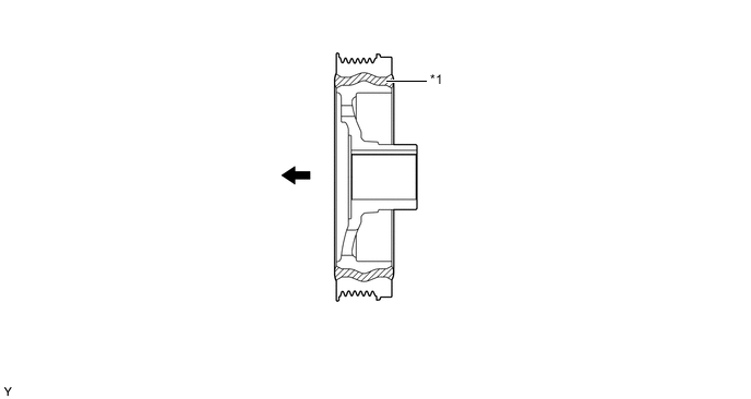
Text in Illustration *1 Torsional Damper Rubber - - Engine Front - -
-
-
Valve Mechanism
-
The camshaft is driven by a timing chain. The camshaft drives the vacuum pump and supply pump in order to reduce the number of parts and realize a lightweight and compact design.
-
The intake and exhaust valves are opened and closed via the No. 1 valve rocker arm sub-assembly.
-
The No. 1 valve rocker arm sub-assembly consists of the rocker arm and roller.
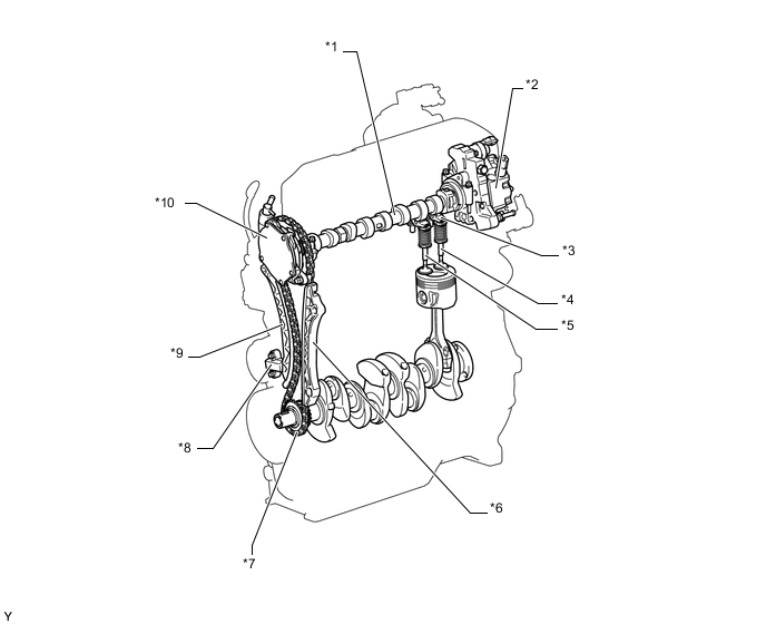
Text in Illustration (Models without DPF:) *1 Camshaft *2 Supply Pump Assembly *3 No. 1 Valve Rocker Arm Sub-assembly *4 Exhaust Valve *5 Intake Valve *6 No. 1 Chain Vibration Damper *7 Chain Sub-assembly *8 No. 1 Chain Tensioner Assembly *9 Chain Tensioner Slipper *10 Vacuum Pump Assembly 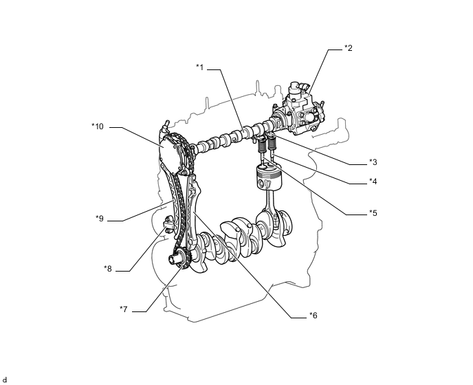
Text in Illustration (Models with DPF:) *1 Camshaft *2 Supply Pump Assembly *3 No. 1 Valve Rocker Arm Sub-assembly *4 Exhaust Valve *5 Intake Valve *6 No. 1 Chain Vibration Damper *7 Chain Sub-assembly *8 No. 1 Chain Tensioner Assembly *9 Chain Tensioner Slipper *10 Vacuum Pump Assembly
-
-
Camshaft
-
The camshaft is made of cast iron.
-
The hollow type camshaft is used to realize light weight.
-
The cam nose is hardened by induction heating to realize excellent durability.
-
A rib, by which the camshaft position sensor detects the cam position, is provided on the camshaft. (Models without DPF)
-
Oil holes are provided in the camshaft in order to supply engine oil to the rocker arm. (Models without DPF)
-
To supply oil to the cylinder head cover sub-assembly, an oil hole has been provided. (Models with DPF)
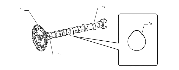
Text in Illustration (Models without DPF:) *1 Camshaft Timing Gear or Sprocket Assembly *2 Camshaft *3 Rib - - *a Induction Hardening - - 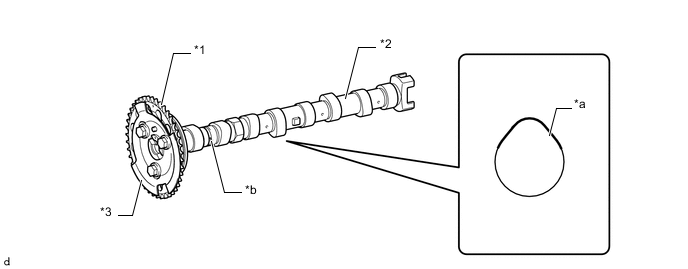
Text in Illustration (Models with DPF:) *1 Camshaft Timing Gear or Sprocket Assembly *2 Camshaft *3 No. 1 Crank Angle Sensor Plate - - *a Induction Hardening *b Oil Hole for Supplying Oil to Cylinder Head Cover Sub-assembly
-
-
No. 1 Valve Rocker Arm Sub-assembly and Valve
-
The rocker arm mechanism consists of the rocker arm, roller and adjusting screw.
-
Narrow valve stems are used to realize light weight.

Text in Illustration *1 Adjusting Screw *2 Roller *3 No. 1 Valve Rocker Arm Sub-assembly - -
-
-
Chain Sub-assembly and Chain Tensioner
-
A bushed chain with 9.525 mm (0.375 in.) pitch is used to realize light weight and maintenance-free operation.
-
An oil jet lubricates the timing chain.
-
The chain tensioner uses a spring and oil pressure to maintain proper chain tension at all times.
-
The chain tensioner suppresses noise generated by the chain.
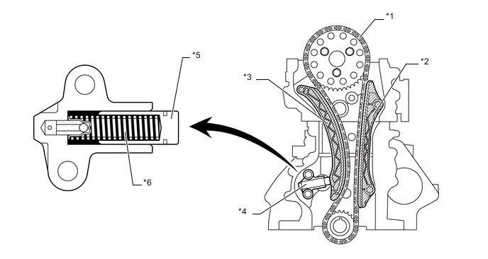
Text in Illustration *1 Chain Sub-assembly *2 Chain Vibration Damper *3 Chain Tensioner Slipper *4 No. 1 Chain Tensioner Assembly *5 Plunger *6 Main Spring
-
-
Serpentine Belt Drive System
-
An automatic tensioner is used. It eliminates the need for tension adjustment.
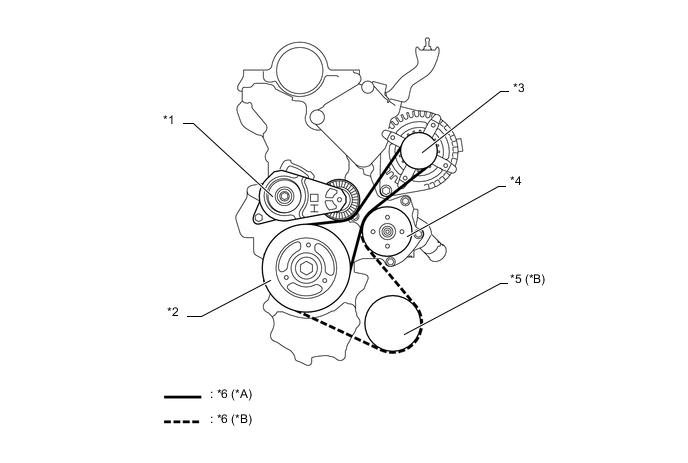
Text in Illustration *A Models without Air Conditioning System *B Models with Air Conditioning System *1
-
Automatic Tensioner
-
Idler Pulley
*2 Crankshaft Pulley *3 Generator Pulley *4 Water Pump Pulley *5 Cooler Compressor Pulley *6 Fan and Generator V Belt -
-
-