ENGINE UNIT
-
CONSTRUCTION
-
Cylinder Head Cover
-
A cylinder head cover made of plastic and integrated with the air cleaner case is used for weight reduction.
-
Acrylic rubber, which excels in heat resistance and reliability, is used for the cylinder head cover gasket.
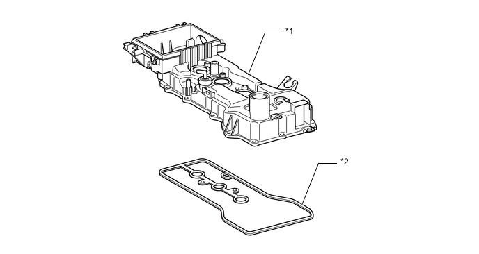
Text in Illustration *1 Cylinder Head Cover Sub-assembly *2 Cylinder Head Cover Gasket
-
-
Cylinder Head Gasket
-
A steel-laminate type cylinder head gasket is used.
-
The surface of the cylinder head gasket is coated with fluorine rubber to ensure a high level of reliability.
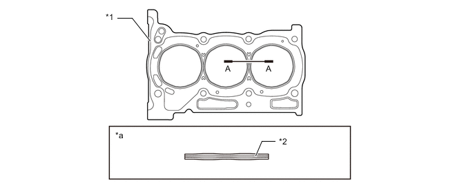
Text in Illustration *1 Cylinder Head Gasket *2 Shim *a A-A Cross Section - -
-
-
Cylinder Head
-
The spark plug has been located in the center of the combustion chamber in order to achieve high the engine's anti-knocking performance.
-
The angle of the intake and exhaust valves is narrowed and set at 33.5° to realize a compact cylinder head.
-
A taper squish combustion chamber is used to achieve high anti-knocking performance and intake efficiency. In addition, excellent engine performance and fuel economy have been realized.
-
The shape of the intake ports has been optimized to realize efficient combustion.
-
The exhaust port for each cylinder is merged inside the cylinder head sub-assembly to accelerate warm-up of the TWC, thus improving the fuel economy. In addition, at high engine speeds, with the effective cooling of the exhaust gases, the operation range for maintaining stoichiometric air-fuel mixture ratio is widened, thus reducing rich air-fuel mixtures and also improving fuel economy.
-
The cylinder head bolt employs plastic region tightening bolts.
-
The routing of the water jacket in the cylinder head is optimized to achieve high cooling performance.
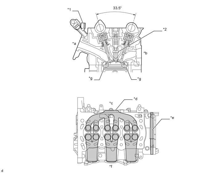
Text in Illustration *1 Fuel Injector Assembly *2 Spark Plug *a Intake Port *b Exhaust Port *c Exhaust Side *d Merged Port *e EGR Gas Passage *f Intake Side *g Taper Squish - -
-
-
Cylinder Block Sub-assembly
-
An aluminum cylinder block sub-assembly with a 7 mm (0.276 in.) distance between the cylinder bores is used to realize a compact and lightweight configuration.
-
It is not possible to bore the block with this liner. The liners are the spiny type, which have been manufactured so that their casting exterior forms a large irregular surface in order to enhance the adhesion between the liners and the aluminum cylinder block sub-assembly. The enhanced adhesion helps heat dissipation, resulting in a lower overall temperature and heat deformation of the cylinder bores.
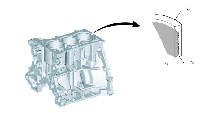
Text in Illustration *a Cylinder Bore Cross Section *b Cylinder Bore *c Irregularly Shaped Outer Casting Surface of Liner - - 
Spiny Type Liner - - -
Through the use of the offset crankshaft, the bore center is shifted 8 mm (0.31 in.) towards the intake, in relation to the crankshaft center. Thus, the side force to cylinder wall is reduced when the maximum pressure is applied, which contributes to fuel economy.
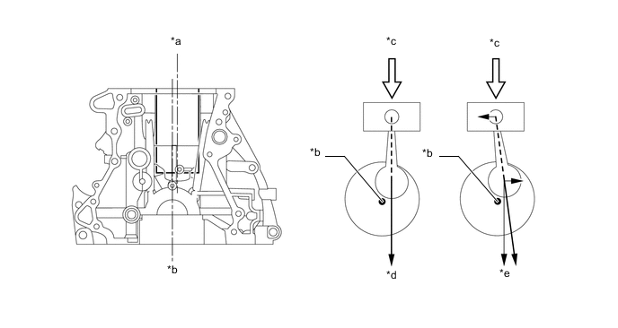
Text in Illustration *a Bore Centerline *b Crankshaft Centerline *c Maximum Pressure *d Offset Crankshaft *e Non-offset Crankshaft - - -
A cylinder block water jacket spacer is used in the water jackets of the cylinder block sub-assembly.
-
They suppress the water flow in the center of the water jackets, guide the coolant above the cylinder bores, and ensure uniform temperature distribution. As a result, the viscosity of the engine oil that acts as a lubricant between the bore walls and the pistons can be lowered, thus reducing friction.
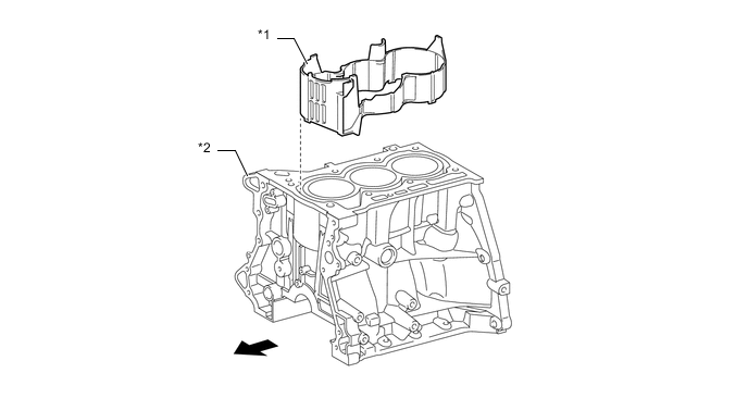
Text in Illustration *1 Cylinder Block Water Jacket Spacer *2 Cylinder Block Sub-assembly 
Engine Front - -
-
-
Piston
-
The piston is made of aluminum alloy.
-
The piston head portion uses a taper squish shape to accomplish fuel combustion efficiency.
-
The piston skirt is coated with resin to reduce friction losses.
-
Low-tension piston rings are used to reduce friction and achieve excellent fuel economy.
-
The No. 1 compression ring, with a thickness of 1.2 mm (0.0472 in.), is used to maintain rigidity to correspond with the higher in-cylinder pressure caused by the increase in the compression ratio.
-
The oil ring is a 3-piece type, and use of the oil ring contributes higher reliability and lower friction.
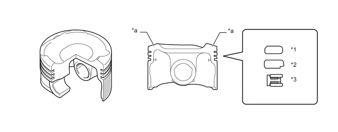
Text in Illustration *1 No. 1 Compression Ring *2 No. 2 Compression Ring *3 Oil Ring - - *a Taper Squish Shape - - Resin Coating - -
-
-
Connecting Rod and Connecting Rod Bearing
-
Connecting rods that have been forged for high strength are used for weight reduction.
-
Plastic region tightening bolts are used.
-
The lining surface of the connecting rod bearing has been micro-grooved to realize an optimal amount of oil clearance. As a result, excellent cold-engine cranking performance has been realized and engine vibrations have been reduced.
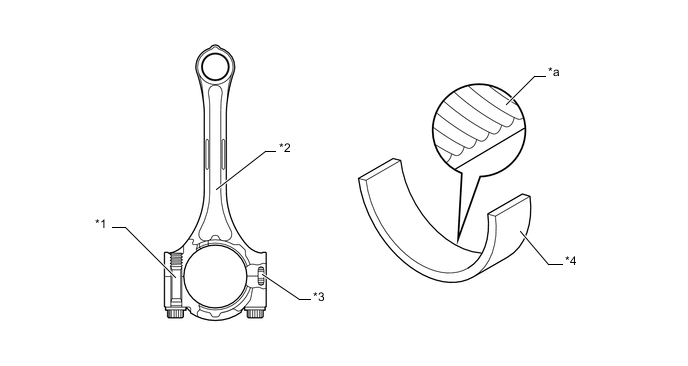
Text in Illustration *1 Plastic Region Tightening Bolt *2 Connecting Rod *3 Knock Pin *4 Connecting Rod Bearing *a Micro-grooved - -
-
-
Crankshaft and Crankshaft Bearing
-
The crankshaft has 4 journals and 6 balance weights.
-
All pins and journal fillets are roll-finished to maintain adequate strength.
-
The lining surface of the crankshaft bearings has been micro-grooved to realize an optimal amount of oil clearance. As a result, excellent cold-engine cranking performance has been realized.
-
The upper main bearing has an oil groove around its inside circumference.
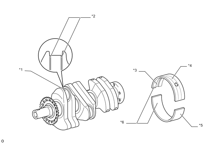
Text in Illustration *1 Oil Hole *2 Roll-Finished *3 Oil Grooved *4 Upper Main Bearing *5 Lower Main Bearing *6 Micro-Grooved
-
-
Oil Pan Sub-assembly
-
Dual-chamber type oil pan, which has a No. 2 oil pan sub-assembly inside an oil pan, is used.
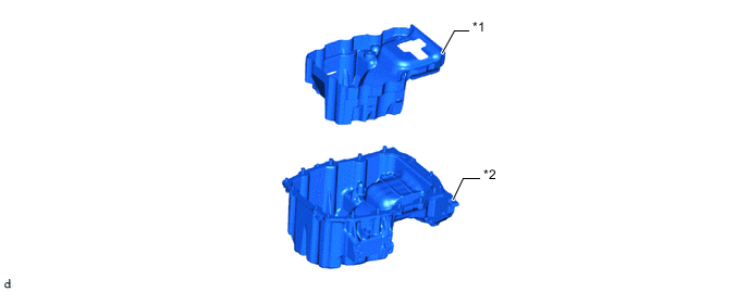
Text in Illustration *1 No. 2 Oil Pan Sub-assembly *2 Oil Pan Sub-assembly -
While the engine is stopped, engine oil in the inner and outer chambers is circulated through the holes in the No. 2 oil pan sub-assembly.
-
While the engine is running, the engine oil inside the No. 2 oil pan sub-assembly is mainly used to accelerate warming up of the engine oil, thus reducing the friction of the engine when cold.
-
A float valve is provided inside the No. 2 oil pan sub-assembly to ensure the capacity of oil replacement between the inner and outer oil pans.
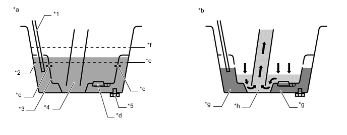
Text in Illustration *1 Engine Oil Level Dipstick Sub-assembly *2 Oil Pan Sub-assembly *3 No. 2 Oil Pan Sub-assembly *4 Oil Strainer Sub-assembly *5 Oil Pan Drain Plug - - *a While engine is stopped. *b While engine is running. *c Hole *d Float Valve *e Lower Oil Level *f Upper Oil Level *g Engine Oil in Outer Pan *h Engine Oil in Inner Pan
-
-
Valve Mechanism
-
Each cylinder has 2 intake valves and 2 exhaust valves. Intake and exhaust efficiency is increased by means of the large total port areas.
-
The valves are directly opened and closed by 2 camshafts.
-
The VVT-i system is used to achieve low fuel consumption, high engine performance and reduce exhaust emissions.
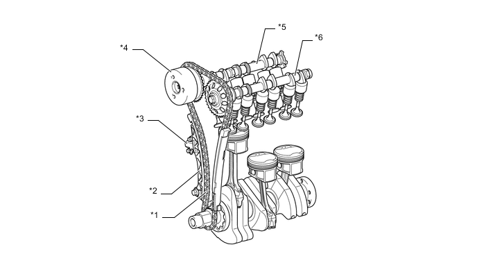
Text in Illustration *1 Timing Chain (Chain Sub-assembly) *2 Timing Chain Tension Arm *3 No. 1 Chain Tensioner Assembly *4 VVT-i Controller (Camshaft Timing Sprocket Assembly) *5 Camshaft *6 No. 2 Camshaft
-
-
Camshaft
-
Oil passages are provided in the intake camshaft in order to supply engine oil pressure to the VVT-i system.
-
A VVT-i controller (camshaft timing sprocket assembly) is installed on the front of the intake camshaft to vary the timing of the intake valves.
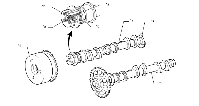
Text in Illustration *1 VVT-i Controller (Camshaft Timing Sprocket Assembly) *2 Camshaft *3 Timing Rotor *4 No. 2 Camshaft *a Oil Passage (Retard) *b Oil Passage (Advance)
-
-
Camshaft Timing Sprocket Assembly
-
The camshaft timing sprocket assembly consists of an outer housing that is driven by the timing chain sprocket, and a vane that is coupled to camshaft.
-
The camshaft timing sprocket assembly uses 3 vanes.
-
When the engine stops, the camshaft timing sprocket assembly is locked at the most retarded angle by its lock pin. This ensures excellent engine startability.
-
The oil pressure sent from the advance or retard side passages of the intake camshaft causes rotation of the vane relative to the timing chain sprocket, to vary the valve timing continuously.
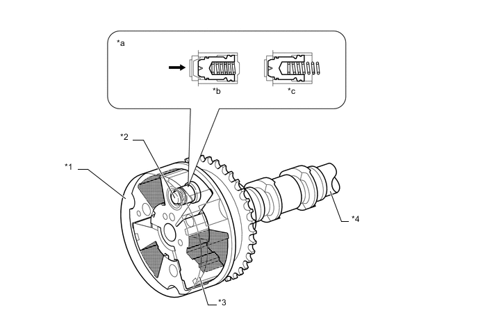
Text in Illustration *1 Housing *2 Lock Pin *3 Vane *4 Intake Camshaft *a Lock Pin Operation *b Engine Operating *c Engine Stopped - - Oil Pressure - -
-
-
Intake and Exhaust Valve and Valve Lifter
-
Narrower valve stems are used to reduce the intake and exhaust resistance and to reduce weight.
-
The same valve springs are used for both the intake and exhaust valves. They are variable pitch springs that offer good valve following performance.
-
Valve lifters with shimless valve adjustment is used for weight reduction.
-
Diamond Like Carbon (DLC) coating is applied to improve fuel efficiency, which is achieved due to reduced friction.
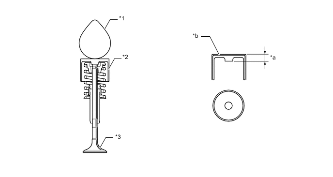
Text in Illustration *1 Cam *2 Valve Lifter *3 Valve - - *a Lifter Thickness *b Diamond Like Carbon (DLC) Coating Tech Tips
The adjustment of the valve clearance is accomplished by selecting and replacing the appropriate valve lifters. Adjusting valve lifters are available in 29 increments of 0.02 mm (0.00079 in.), from 5.12 mm (0.201 in.) to 5.68 mm (0.223 in.).
-
-
Timing Chain (Chain Sub-assembly) and Chain Tensioner
-
A high-strength roller chain with an 8.0 mm (0.315 in.) pitch is used to make the engine more compact and to ensure the reliability of the timing chain (chain sub-assembly).
-
The No. 1 chain tensioner assembly uses a spring and oil pressure to maintain proper chain tension at all times. The No. 1 chain tensioner assembly suppresses noise generated by the timing chain (chain sub-assembly).
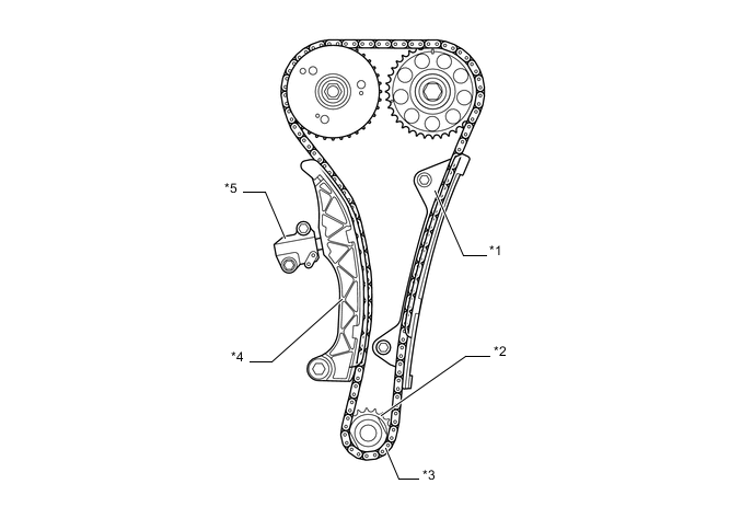
Text in Illustration *1 Timing Chain Guide *2 Crankshaft Timing Gear or Sprocket *3 Timing Chain (Chain Sub-assembly) *4 Timing Chain Tension Arm *5 No. 1 Chain Tensioner Assembly - -
-
-
Timing Chain Cover Sub-assembly
-
The oil pump housing is enclosed in a timing chain cover sub-assembly made of aluminum, to which an engine water pump assembly is mounted.
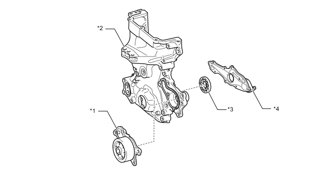
Text in Illustration *1 Engine Water Pump Assembly *2 Timing Chain Cover Sub-assembly *3 Oil Pump Rotor *4 Oil Pump Housing
-
-
Fan and Generator V Belt
-
Accessory components are driven by a serpentine belt consisting of a single V-ribbed belt. It reduces the overall engine length, weight and the number of engine parts.
-
An automatic v-ribbed belt tensioner assembly eliminates the need for tension adjustment.
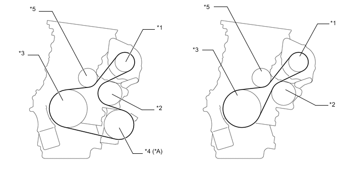
Text in Illustration *A Models with Air Conditioning System - - *1 Generator with Clutch Pulley *2 Water Pump Pulley *3 Crankshaft Pulley *4 Compressor with Pulley Assembly *5 V-ribbed Belt Tensioner Assembly - -
-
-
Crankshaft Pulley
-
The rigidity of the crankshaft pulley with its built-in torsional damper rubber reduces noise.

Text in Illustration (Crankshaft Pulley Cross Section:) *1 Torsional Damper Rubber - - Front - -
-
-