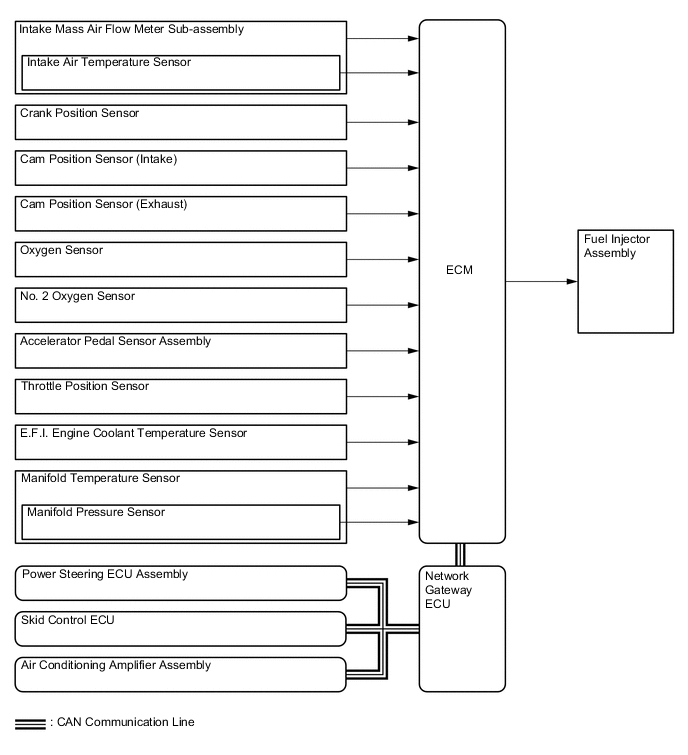
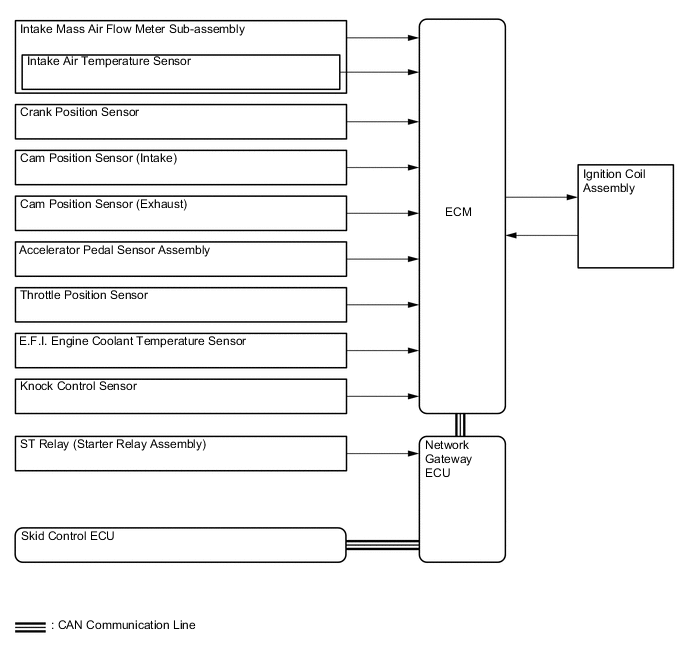
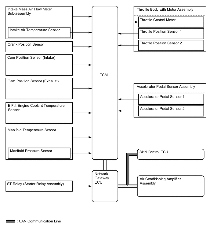
SFI SYSTEM
-
FUNCTION OF MAIN COMPONENTS
-
The main components of the 2ZR-FE engine control system are as follows.
Components Outline Quantity Function ECM 32-bit CPU 1 Optimally controls the engine control system to suit the operating conditions of the engine in accordance with the signals provided by the sensors. Intake Mass Air Flow Meter Sub-assembly Hot-wire Type 1 Uses a built-in hot-wire to directly detect the intake air mass. Crank Position Sensor [Rotor Teeth] Pick-up Coil Type [36 - 2] 1 Detects the engine speed and the crank angle. Cam Position Sensor [Rotor Teeth] Magneto Resistive Element (MRE) Type [3] 2 Performs cylinder identification and detects the VVT angle. Accelerator Pedal Sensor Assembly Non-contact Type 1 Detects the amount of pedal effort applied to the accelerator pedal. Throttle Body with Motor Assembly Throttle Position Sensor Non-contact Type 1 Detects the throttle valve opening angle. Throttle Control Motor DC Motor 1 Regulates the opening of the throttle valve in accordance with the signals from the ECM. Camshaft Timing Oil Control Valve Assembly Solenoid Type 2 Changes the oil passage to the camshaft timing gear assembly and the camshaft timing exhaust gear assembly in response to signals from the ECM. E.F.I. Engine Coolant Temperature Sensor Thermistor Type 1 Detects the water temperature by means of an internal thermistor. Oxygen Sensor Type with Heater (Planar Type) 1 Detects the oxygen concentration in the exhaust emissions by measuring the electromotive force generated in the sensor itself. No. 2 Oxygen Sensor Type with Heater (Cup Type) 1 Knock Control Sensor Built-in Piezoelectric Element Type (Flat Type) 1 Detects an occurrence of engine knocking indirectly from the vibration of the cylinder block caused by the occurrence of engine knocking. Manifold Temperature Sensor Silicon Chip Type 1 Detects the temperature and pressure in the air intake pipe after supercharging. Ignition Coil Assembly Type with Igniter 4 Incorporates an igniter and provides the high voltage electricity necessary for ignition in accordance with signals from the ECM. Spark Plug Iridium-tipped Type 4 Produces a spark inside the cylinder using high voltage electricity delivered from the ignition coil assembly. Fuel Injector Assembly 12-hole Type 4 Is an electromagnetically-operated nozzle which injects fuel in accordance with the signals from the ECM. Network Gateway ECU Gateway Function 1 Sends signals to and receives signals from the ECM.
-
-
SYSTEM CONTROL
-
The engine control system of the 2ZR-FE engine has the following systems.
System Function Sequential Multiport Fuel Injection (SFI)
-
An L-type SFI system detects the intake air mass with a hot-wire type mass air flow meter sub-assembly.
-
The fuel injection system is a sequential multiport fuel injection system.
Electronic Spark Advance (ESA) Ignition timing is determined by the ECM based on signals from various sensors. The ECM corrects ignition timing in response to engine knocking. Electronic Throttle Control System-intelligent (ETCS-i) Optimally controls the throttle valve opening in accordance with the amount of accelerator pedal effort, the throttle valve opening control request from the ECM, and the condition of the engine and the vehicle. Dual Variable Valve Timing-intelligent (Dual VVT-i) Regulates operation of the intake and exhaust camshafts to ensure an optimal valve timing in accordance with engine operating conditions. Cooling Fan Control Cooling fan operation is controlled by signals from the ECM based on the E.F.I. engine coolant temperature sensor signal. Fuel Pump Control
-
Fuel pump operation is controlled by signals from the ECM.
-
The fuel pump is stopped when any of the Supplemental Restraint System (SRS) airbags are deployed.
Evaporative Emission Control The ECM controls the purge flow of evaporative emissions (HC) from the charcoal canister in accordance with engine conditions. Air Conditioning Cut-off Control By turning the air conditioning compressor on or off in accordance with engine operating conditions, driveability is maintained. Oxygen Sensor Heater Control Maintains the temperature of the oxygen sensor and No. 2 oxygen sensor at an appropriate level to increase accuracy of detection of the oxygen concentration in the exhaust gas. Engine Immobiliser Prohibits fuel delivery and ignition if an attempt is made to start the engine with an invalid ignition key. Brake Override System When the accelerator and brake pedals are depressed at the same time, the motive force may be restrained. (For the Activation Conditions and Inspection Method, refer to the Repair Manual.) -
-
Sequential Multiport Fuel Injection (SFI)
-
EFI-L, which uses an intake mass air flow meter sub-assembly to detect intake air volume and subsequently control fuel injection volume, is used.
-
Synchronous injection timing (1 injection per cylinder for every 2 crankshaft rotations) is used.
-
There are 2 fuel injection modes, a synchronous injection and asynchronous injection. In synchronous injection, the basic injection duration is corrected based on signals from each sensor to always inject fuel at the same position. In asynchronous injection, fuel is injected at the point the injection request is detected according to signals from each sensor regardless of the crankshaft angle. In addition, to protect the engine and improve fuel efficiency, a fuel cut that stops fuel injections will be implemented according to the operating conditions.
-
Fuel injection is stopped to protect the engine and improve fuel efficiency.
Fuel Cut Fuel Cut Off During Deceleration If the engine speed is above a standard value when decelerating (when the ECM determines that the throttle is off), the fuel injection is stopped to prevent overheating of the catalyst by misfiring, and to improve fuel efficiency. If the coolant temperature is low, the fuel cut speed and restoration speed will be increased. Fuel Cut According to Engine Speed If the engine speed is higher than a standard value, fuel injection is stopped to prevent excessive speed. Fuel Cut Speed at High Engine Speed Engine Speed When Driving (rpm) 7000 or more Fuel Cut Speed When Vehicle Stopped Engine Speed When Vehicle Stopped (rpm) 3300 or more
-
-
Electronic Spark Advance (ESA)
-
The optimum ignition timing is selected according to signals from the sensors and the ignition signal (IGt) is sent to the igniter.
-
The ignition timing can be expressed using the following equation. The ignition timing is set initially to 10° BTDC.
Ignition Timing = A. Initial Set Ignition Timing or B. Basic Advanced Angle + C. Corrected Advanced Angle A. Fixed Advanced Angle Characteristics Fixed to 5° BTDC when starting the engine. The service terminals are short-circuited, and it is fixed to 10° BTDC when the throttle is closed. B. Basic Advanced Angle Characteristics Selects the optimum ignition timing, depending on each sensor signal. C. Correction Advanced Angle Characteristics Selects the appropriate advanced or retarded angles according to the engine status at that time, depending on each sensor signal. C-1. Warm-up Advanced Angle Characteristics Sets the ignition timing to advanced angle according to the operating status to improve drivability, when the coolant temperature is low. C-2. Idling Stability Advanced Angle Characteristics Sets the ignition timing to advance to stabilize idle speed when the idle speed is low. Also, as the speed gets higher, the ignition timing is retarded. C-3. Knocking Correction Retarded Angle When knocking is generated, the ignition timing is corrected according to a signal from the knock control sensor. -
If engine knocking is detected, the ignition timing is retarded gradually in equal steps according to the size of knocking, until the engine stops knocking.
-
After knocking has stopped, the ignition timing is advanced gradually in equal steps. If the engine knocks again during this process, then the ignition timing is retarded again.
Figure 1. Knocking Feedback Control Cycle

*1 Knocking Occurs *2 Retard *3 Advance *4 No Knocking
-
-
Electronic Throttle Control System-intelligent (ETCS-i)
-
By controlling the engine output optimally for the accelerator pedal opening angle with centralized control using the ECM, good accelerator controllability and vehicle stability are enabled across all speed ranges.
-
Ordinary throttle valve opening angle control (non-linear control) and the idle speed control (ISC) functions have been brought together in the throttle body with motor assembly.
-
By integrated control with the powertrain, superior operability is ensured and comfort is improved.
-
To enable driving in the event of trouble, the system is duplicated to ensure reliability.
ETCS-i Control Driving Control Controls the opening angle of the throttle valve in order to produce engine output in response to the driving conditions and the accelerator pedal opening angle. TRC/VSC Cooperative Control Stabilizes the vehicle by communicating with the skid control ECU when the TRC and VSC are operating. Idle Speed Control Controls the fast idle speed to suit the engine coolant temperature and the idle speed after the engine is warmed up. In addition, it controls the idle speed in accordance with the fuel injection volume and throttle position.
-
-
Dual Variable Valve Timing-intelligent (Dual VVT-i)
-
Using the engine speed, intake air mass, throttle position, manifold pressure and engine coolant temperature, the ECM can calculate the optimal valve timing for each driving condition and can control the camshaft timing oil control valve assembly. In addition, the ECM uses signals from the crank position sensor and cam position sensor to detect the actual valve timing, thus providing feedback control to achieve the target valve timing.
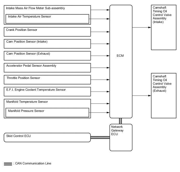
-
The dual VVT-i system delivers excellent benefit in vehicle states as shown in the table below.
-
During Idle

*1 TDC *2 Most Retarded *3 BDC Objective Effect Eliminating overlap to reduce blowback to the intake side.
-
Stabilized idle speed
-
Better fuel economy
-
-
At Light Load

*1 To Retarded Side Objective Effect Eliminating overlap to reduce blowback to the intake side. Ensures engine stability
-
At Medium Load

*1 To Advanced Side Objective Effect Increasing overlap to increase internal EGR to reduce pumping losses.
-
Better fuel economy
-
Improved emission control
-
-
In Low to Medium Speed Range with Heavy Load

*1 To Advanced Side Objective Effect Advancing the intake valve close timing for volumetric efficiency improvement. Improved torque in low to medium speed range
-
In High Speed Range with Heavy Load

*1 To Retarded Side Objective Effect Retarding the intake valve close timing for volumetric efficiency improvement Improved output
-
At Low Temperatures

Objective Effect Eliminating overlap to reduce blowback to the intake side stabilizes the idle speed during fast idle.
-
Stabilized idling engine speed
-
Better fuel economy
-
-
Upon Starting the Engine / Upon Stopping the Engine

*1 Most Retarded Objective Effect Eliminating overlap to minimize blowback to the intake side. Improved startability
-
-
-
Cooling Fan Control
-
According to the cooling fan drive request signal (low or high) from the air conditioning amplifier assembly and the engine coolant temperature, the ECM regulates the cooling fan speed over 2 levels. A cooling fan drive request signal is determined by the air conditioning amplifier assembly depending on mainly the refrigerant pressure and the A/C switch status.
-
The low speed operation is accomplished by applying the current through a resistor, which reduces the speed of the cooling fan.
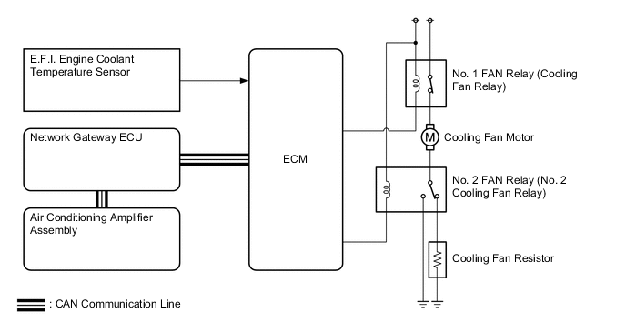
Cooling Fan Operation Engine Coolant Temperature Cooling Fan Drive Request Signal Cooling Fan Operation Low Off Off Low Low High High High Off High Low High High High
-
-
Fuel Pump Control
-
Fuel Cut Control
-
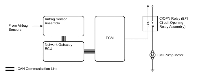
The fuel pump control is used to stop the fuel pump when the airbags deploy in a collision.
-
In this system, the airbag deployment signal from the airbag sensor assembly is detected by the ECM, which turns off the C/OPN relay (EFI circuit opening relay assembly).
-
After the fuel cut control has been activated, turning the engine switch from off to on (IG) cancels the fuel cut control, and the engine can be restarted.
-
-
-
-
CONSTRUCTION
-
Air Flow Meter
-
The compact and lightweight plug-in type intake mass air flow meter sub-assembly allows a portion of the intake air to flow through the detection area. By directly measuring the mass flow rate of the intake air, the detection precision is improved and the intake air resistance has been reduced.
-
This intake mass air flow meter sub-assembly has a built-in intake air temperature sensor.
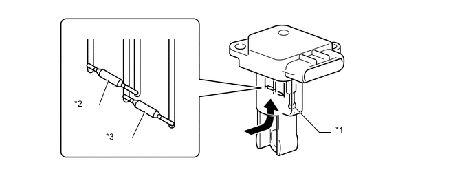
*1 Intake Air Temperature Sensor *2 Temperature Sensing Element *3 Hot-wire Element - - 
Air Flow - -
-
-
Crank Position Sensor and Cam Position Sensor
-
A pick-up coil type crank position sensor is used. The No. 1 crankshaft position sensor plate of the crankshaft consists of 34 teeth, with 2 teeth missing. The crank position sensor outputs the crankshaft rotation signals every 10°, and the missing teeth are used to determine the top-dead-center.
-
A Magneto Resistive Element (MRE) type cam position sensor is used. To detect the camshaft position, each timing rotor on the intake and exhaust camshafts is used to generate 3 (3 high output, 3 low output) pulses for every 2 revolutions of the crankshaft.
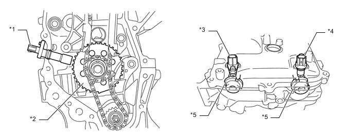
*1 Crank Position Sensor *2 No. 1 Crankshaft Position Sensor Plate *3 Cam Position Sensor (Intake) *4 Cam Position Sensor (Exhaust) *5 Timing Rotor (Camshaft) - - Figure 2. Sensor Output Waveforms
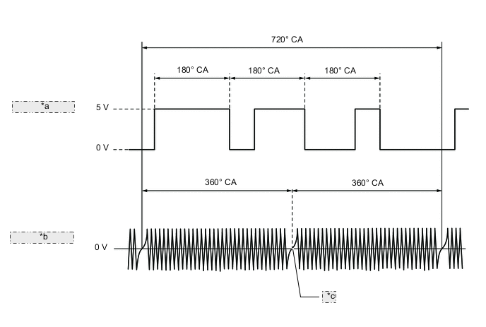
*a Cam Position Sensor (for Intake Camshaft) *b Crank Position Sensor *c 2 Teeth Missing -
The MRE type cam position sensor consists of an MRE, a magnet and a sensor. The direction of the magnetic field changes due to the differing shape (protruded and non-protruded portions) of the timing rotor, which passes by the sensor. As a result, the resistance of the MRE changes, and the output voltage to the ECM changes to high or low. The ECM detects the camshaft position based on this output voltage.
-
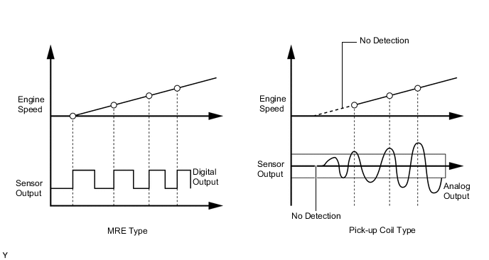
The differences between the MRE type cam position sensor and the pick-up coil cam position sensor used on the conventional model are as follows:
Item Sensor Type MRE Pick-up Coil Signal Output Constant digital output starts from low engine speeds. Analog output changes with the engine speed. Camshaft Position Detection Detection is made by comparing the NE signals with the high/low output switch timing due to the protruded/non-protruded portions of the timing rotor, or made based on the number of the input NE signals during high/low outputs. Detection is made by comparing the NE signals with the change of waveform that is output when the protruded portion of the timing rotor passes. Figure 3. MRE Type and Pick-up Type Output Waveform Image Comparison
-
-
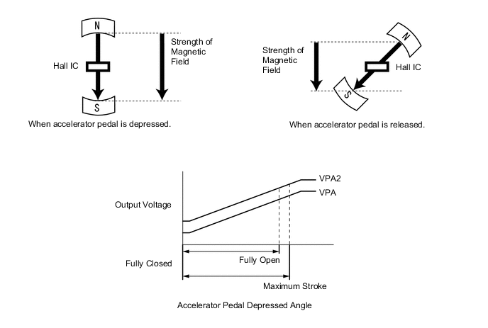
Accelerator Pedal Sensor
-
A non-contact type accelerator pedal sensor assembly is used.
-
This sensor uses a Hall IC*1, which can retrieve the strength of the magnetic field as an electrical signal, using the Hall effect*2, in which the output voltage can be directly received in accordance with the accelerator pedal depression amount. When the accelerator pedal depression amount changes, the angle of the magnetic field towards the flow of the current in the Hall IC changes. As a result, the strength of the current and vertical magnetic field changes. Due to this, the change in the voltage generated in the vertical direction towards the forced current and direction of the magnetic field is sent to the ECM as an accelerator pedal depression amount signal. Also, in order to ensure reliability, duplicate sensors (main and sub) with differing sensor output characteristics, are used.
Tech Tips
*1: An electrical component which uses the electromotive force resulting from the potential difference in the magnetic field.
*2: Phenomenon in which a potential difference occurs in the electric current and magnetic field in the vertical direction when a magnetic field in the vertical direction is applied and electric current is flowing through a rod or plated conductor or semiconductor.
-
-
Throttle Position Sensor
-
A non-contact type throttle position sensor is used.
-
This sensor uses a Hall IC*1, which can retrieve the strength of the magnetic field as an electrical signal using Hall effect*2, in which the output voltage can be directly received in accordance with the throttle valve opening angle. When the throttle valve opening angle changes, the angle of the magnetic field towards the flow of the current in the Hall IC changes. As a result, the strength of the current and vertical magnetic field changes. Due to this, the change in the voltage generated in the vertical direction towards the current and direction of the magnetic field is sent to the ECM as a throttle valve opening angle signal. Also, duplicate sensors (main and sub) with differing sensor output characteristics, are used, ensuring reliability.
Tech Tips
*1: An electrical component which uses the electromotive force resulting from the potential difference in the magnetic field.
*2: Phenomenon in which a potential difference occurs in the electric current and magnetic field in the vertical direction when a magnetic field in the vertical direction is applied and electric current is flowing through a rod or plated conductor or semiconductor.
Figure 4. Sensor Output Characteristics
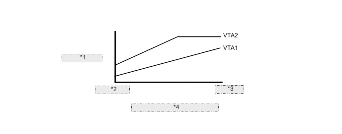
*1 Output Voltage *2 Fully Closed *3 Fully Open *4 Throttle Valve Opening Angle
-
-
Throttle Body
-
A single valve type electronic control throttle body with motor assembly that drives the throttle valve by a motor to ensure excellent driving stability.
-
A DC motor with good response and low power consumption is adopted for the motor for throttle valve drive.
-
Driver operations (the amount of the accelerator pedal being depressed) are transmitted to the ECM by the accelerator pedal sensor assembly provided on the accelerator pedal. The ECM determines the throttle valve opening angle that matches the driving status to drive the throttle control motor. The throttle valve opening angle is fed back to the ECM by the throttle position sensor.
-
When an error is detected, the driver is notified by a warning light in the combination meter assembly and current to the motor is cut. This causes the throttle valve to return to its predetermined angle by the throttle valve return spring. Fuel cut and ignition retard adjust the engine output according to the accelerator pedal opening angle to allow the vehicle to continue at a minimal speed.
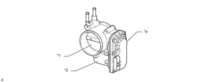
*1 Throttle Valve *2 Throttle Control Motor *a Throttle Position Sensor Portion - -
-
-
Camshaft Timing Oil Control Valve
-
This camshaft timing oil control valve assembly controls the spool valve using duty cycle control from the ECM. This allows hydraulic pressure to be applied to the VVT-i controller (camshaft timing gear assembly and camshaft timing exhaust gear assembly) advanced or retarded side. When the engine is stopped, the camshaft timing oil control valve assembly (for intake camshaft) will move to the retard position, and the camshaft timing oil control valve assembly (for exhaust camshaft) will move to the advanced position.
Figure 5. Intake Side
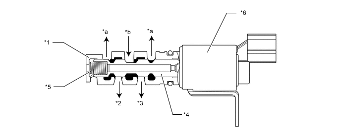
*1 Sleeve *2 To VVT-i Controller (Camshaft Timing Gear Assembly) (Advanced Side) *3 To VVT-i Controller (Camshaft Timing Gear Assembly) (Retard Side) *4 Spool Valve *5 Spring *6 Camshaft Timing Oil Control Valve Assembly *a Drain *b Oil Pressure Figure 6. Exhaust Side
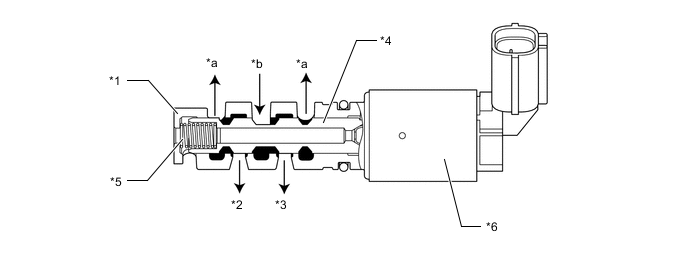
*1 Sleeve *2 To VVT-i Controller (Camshaft Timing Exhaust Gear Assembly) (Retard Side) *3 To VVT-i Controller (Camshaft Timing Exhaust Gear Assembly) (Advanced Side) *4 Spool Valve *5 Spring *6 Camshaft Timing Oil Control Valve Assembly *a Drain *b Oil Pressure
-
-
Water Temperature Sensor
-
This sensor detects the engine coolant temperature. A thermistor whose resistance value greatly changes according to the temperature is built-in. Changes in the coolant temperature are detected by the changes in the thermistor resistance value.
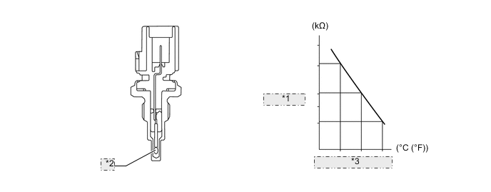
*1 Resistance *2 Thermistor *3 Coolant Temperature
-
-
Oxygen Sensor
-
The oxygen sensor is a wide band type sensor that can detect ratios into the lean range.
-
Constructed of planar zirconia, the Nernst cell reacts with the oxygen in the exhaust gas and generates an output voltage. The ECM then drives a pumping cell in order to keep the generated output voltage at a constant value. By detecting that pumping cell drive voltage, the oxygen concentration and therefore the air fuel ratio can be determined.
-
The sensor element is heated by the integrated heater, thus keeping the zirconia at a constant temperature in order to facilitate feedback control.
*1 Sensor Element (Zirconia) *2 Diffusion Gap *3 Reference Air *4 Heater *5 Pumping Cell (Zirconia) *6 Nernst Cell (Zirconia) Exhaust Gas - -
-
-
No. 2 Oxygen Sensor
-
The output voltage of the No. 2 oxygen sensor changes in accordance with the oxygen concentration in the exhaust gas. The ECM uses this output voltage to determine whether the present air fuel ratio is richer or leaner than the stoichiometric air fuel ratio.
-
The sensor element is heated by the integrated heater, thus keeping the zirconia at a constant temperature in order to facilitate feedback control.
*1 Heater *2 Sensor Element (Zirconia) *3 Platinum Electrode *4 Atmosphere
-
-
Knock Control Sensor
-
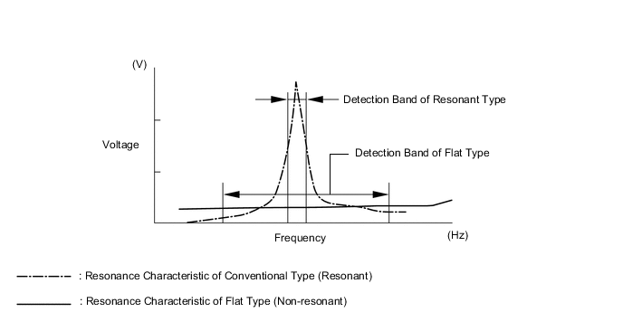
In a conventional knock control sensor (resonant type), a vibration plate is built into the sensor. This plate has the same resonance point as the knocking frequency of the engine block. This sensor can only detect vibration in this frequency band.
-
A flat type knock control sensor (non-resonant type) has the ability to detect vibration in a wider frequency band (from about 5 kHz to 15 kHz). It has the following features.
-
The engine knocking frequency will vary slightly depending on the engine speed. The flat type knock control sensor can detect vibration even when the engine knocking frequency changes. Due to the use of the flat type knock control sensor, the vibration detection ability is increased compared to a conventional type knock control sensor, and more precise ignition timing control is possible.
Figure 7. Characteristics of Knock Control Sensor
-
A flat type knock control sensor is installed to an engine by placing it over the stud bolt installed on the cylinder block sub-assembly. For this reason, a hole for the stud bolt exists in the center of the sensor.
-
In the sensor, a steel weight is located in the upper portion. An insulator is located between the weight and a piezoelectric element.
-
An open/short circuit detection resistor is integrated in the sensor. When the ignition is ON, the open/short circuit detection resistor in the knock control sensor and the resistor in the ECM keep the voltage at terminal KNK1 constant. An Integrated Circuit (IC) in the ECM constantly monitors the voltage of terminal KNK1. If the open/short circuit occurs between the knock control sensor and the ECM, the voltage of terminal KNK1 will change and the ECM will detect the open/short circuit and store a Diagnostic Trouble Code (DTC).
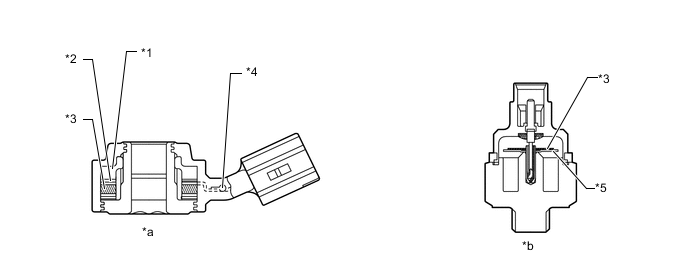
*1 Steel Weight *2 Insulator *3 Piezoelectric Element *4 Open/Short Circuit Detection Resistor *5 Vibration Plate - - *a Flat Type Knock Control Sensor (Non-resonant Type) *b Conventional Type Knock Control Sensor (Resonant Type) 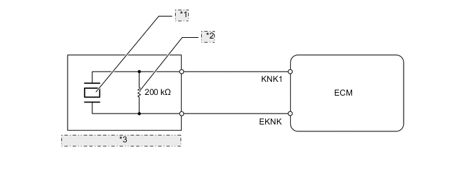
*1 Piezoelectric Element *2 Open/Short Circuit Detection Resistor *3 Flat Type Knock Control Sensor -
Vibrations caused by knocking are transmitted to the steel weight. The inertia of this weight applies pressure to the piezoelectric element. This action generates electromotive force.

*1 Steel Weight *2 Piezoelectric Element Inertia - -
-
-
Manifold Temperature Sensor
-
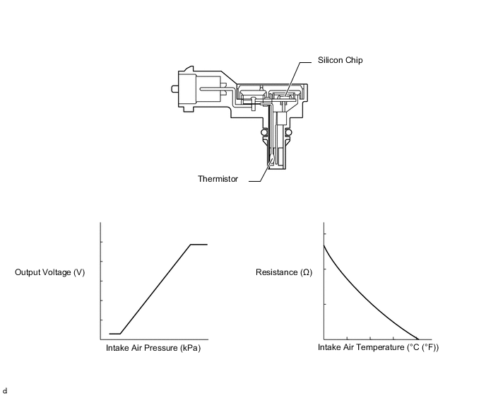
The manifold temperature sensor has a built-in manifold pressure sensor.
-
The manifold pressure sensor consists of a silicon chip which utilizes the characteristic of a silicon chip that changes its electrical resistance when pressure is applied to it. The sensor converts the pressure into an electrical signal, and sends it to the ECM in an amplified form.
-
The manifold temperature sensor detects the intake air temperature via a thermistor.
-
-
Ignition Coil
-
The Direct Ignition System (DIS) provides 4 ignition coil assemblies, one for each cylinder. The spark plug caps, which provide contact to spark plugs, are integrated with the ignition coil assembly. Also, an igniter is enclosed to simplify the system.
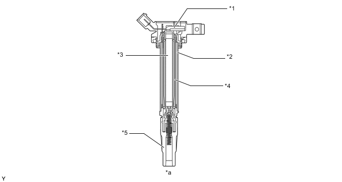
*1 Igniter *2 Primary Coil *3 Iron Core *4 Secondary Coil *5 Plug Cap - - *a Ignition Coil Assembly Cross Section - -
-
-
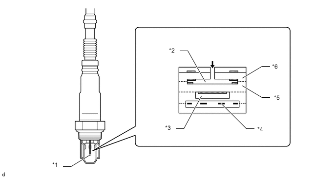
Spark Plug
-
Long-reach, thin-electrode type iridium-tipped spark plugs are used. This type of spark plugs allows the area of the cylinder head sub-assembly to receive the spark plugs to be made thick. Thus, the water jacket can be extended near the combustion chamber, which contributes to cooling performance.
-
Iridium-tipped spark plugs improve ignition performance while maintaining the same durability as platinum-tipped spark plugs.
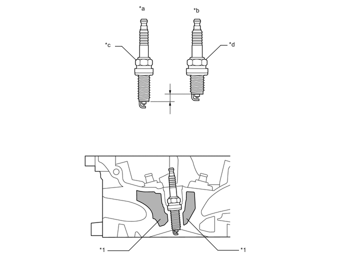
*1 Water Jacket - - *a Long-reach Type *b Conventional Type *c Hex. 14 mm *d Hex. 16 mm Tech Tips
Be sure to use a spark plug wrench of the proper size because the size of the spark plugs is different from conventional spark plugs.
-
-
-
FAIL-SAFE
-
When the ECM detects a malfunction, the ECM stops or controls the engine according to the data already stored in the memory. For details, refer to the Repair Manual.
-
-
DIAGNOSIS
-
When the ECM detects a malfunction, the ECM diagnoses and memorizes the failed section. For details, refer to the Repair Manual.
-