SFI SYSTEM
-
FUNCTION OF MAIN COMPONENTS
-
The main components of the 2NR-FKE engine control system are as follows.
Components Outline Quantity Function ECM 32-bit CPU 1 The ECM optimally controls the SFI, ESA, EGR and ETCS-i to suit the operating conditions of the engine in accordance with the signals provided by the sensors. Intake Mass Air Flow Meter Sub-assembly Hot-wire Type 1 This sensor uses a built-in hot-wire to directly detect the intake air mass. Crank Position Sensor [Rotor Teeth] Magneto Resistive Element (MRE) Type [36-2] 1 This sensor detects the engine speed and performs cylinder identification. Cam Position Sensor (No. 1 Crank Position Sensor) [Rotor Teeth] Magneto Resistive Element (MRE) Type [3] 2 This sensor performs cylinder identification. Accelerator Pedal Sensor Assembly Non-contact Type 1 This sensor detects the amount of pedal effort applied to the accelerator pedal. Throttle Position Sensor Non-contact Type 1 This sensor detects the throttle valve opening angle. Throttle Control Motor DC Motor 1 Regulates the opening of the throttle valve in accordance with the signals from the ECM. Cam Timing Control Motor with EDU Assembly EDU-integrated (Brushless Type DC Motor) 1 The rotational movement of the cam timing control motor with EDU assembly changes the intake valve timing by operating the camshaft timing gear assembly in accordance with the signals received from the ECM. Camshaft Timing Oil Control Valve Assembly Solenoid Type 1 This solenoid changes the oil passage to the camshaft timing exhaust gear assembly in response to signals from the ECM. E.F.I. Engine Coolant Temperature Sensor Thermistor Type 1 This sensor detects the water temperature by means of an internal thermistor. Oxygen Sensor Cup Type with Heater 1 This sensor detects the oxygen concentration in the exhaust emission by measuring the electromotive force which is generated in the sensor itself. Air Fuel Ratio Sensor Planar Type with Heater 1 As with the oxygen sensor, this sensor detects the oxygen concentration in the exhaust gas. However, it detects the oxygen concentration in the exhaust gas linearly. No. 1 Ignition Coil Type with Igniter 4 Incorporates an igniter and provides the high voltage electricity necessary for ignition in accordance with signals from the ECM. Spark Plug Iridium-tipped Type 4 Produces a spark inside the cylinder using high voltage electricity delivered from the ignition coil assembly. Fuel Injector Assembly 8-hole Type 4 The fuel injector is an electromagnetically-operated solenoid with a nozzle which injects fuel in accordance with signals from the ECM. EGR Valve Assembly Step Motor Type 1 This valve opens and closes based on signals from the ECM and controls the flow rate of the exhaust gas in the EGR bypass.
-
-
SYSTEM CONTROL
-
The engine control system of the 2NR-FKE engine has the following systems.
System Function Sequential Multiport Fuel Injection (SFI) An L-type SFI system is used, the intake air mass is detected with a hot-wire type intake mass air flow meter sub-assembly. The fuel injection system is a sequential multiport fuel injection system. Electronic Spark Advance (ESA) The ECM determines the optimal ignition timing in accordance with the signals received from the sensors and sends (IGt) ignition signal to the igniter. The ECM corrects ignition timing in response to engine knocking. Electronic Throttle Control System-intelligent (ETCS-i) Optimally controls the throttle valve opening in accordance with the amount of accelerator pedal effort, the throttle valve opening control request from the ECM, and the condition of the engine and the vehicle. Dual Variable Valve Timing-intelligent (VVT-iE and VVT-i) Regulates operation of the intake and exhaust camshafts to ensure optimal valve timing in accordance with engine operating conditions. Exhaust Gas Recirculation (EGR) Control By controlling the EGR amount according to the operating status, NOx and pumping loses are reduced. Cooling Fan Control Cooling fan operation is controlled by signals from the ECM based on the E.F.I. engine coolant temperature sensor signal. Fuel Pump Control
-
Based on signals from the ECM, the fuel pump control ECU controls the fuel pump.
-
The fuel pump is stopped when a SRS airbag is deployed.
Evaporative Emission Control The ECM controls the purge flow of evaporative emissions (HC) from the charcoal canister in accordance with engine conditions. Brake Booster Vacuum Ejector Control The ECM controls the No. 2 vacuum switching valve assembly to compensate for the reduction in negative pressure of the brake booster assembly. Charging Control The ECM regulates the charging voltage of the generator assembly in accordance with the driving conditions and the charge state of the battery. This reduces the load on the engine, contributing to the fuel economy of the engine. Air Conditioning Cut-off Control*1
-
By turning the air conditioning compressor on or off in accordance with engine operating conditions, drivability is maintained.
-
By using the pressure inside the brake booster and the atmospheric pressure to calculate the negative pressure inside the brake booster, the compressor assembly operation stop time is optimized and the engine load is reduced, reducing the pressure inside the intake manifold and maintaining the negative pressure of the brake booster.
Air Fuel Ratio Sensor and Oxygen Sensor Heater Control Maintains the temperature of the air fuel ratio sensor and oxygen sensor at an appropriate level to increase the detection accuracy of the exhaust gas oxygen concentration. Early Stage Injection Control*2 The ECM calculates appropriate injection and ignition at an early stage. The ECM uses these calculated values when the engine is stopped due to stop and start system control. Engine Immobiliser Prohibits fuel delivery and ignition if an attempt is made to start the engine with an invalid ignition key. Brake Override System When the accelerator and brake pedals are depressed at the same time, the motive force may be restrained. (For the Activation Conditions and Inspection Method, refer to the Repair Manual.) *1: Models with air conditioning system
*2: Models with stop and start system
-
-
Sequential Multiport Fuel Injection (SFI)
-
EFI-L, which uses an intake mass air flow meter sub-assembly to detect intake air volume and subsequently control fuel injection volume, is used.
-
Synchronous injection timing (1 injection per cylinder for every 2 crankshaft rotations) is used.
-
There are 2 fuel injection modes, a synchronous injection and asynchronous injection. In synchronous injection, the basic injection duration is corrected based on signals from each sensor to always inject fuel at the same position. In asynchronous injection, fuel is injected at the point the injection request is detected according to signals from each sensor regardless of the crankshaft angle. In addition, to protect the engine and improve fuel efficiency, a fuel cut that stops fuel injections will be implemented according to the operating conditions.
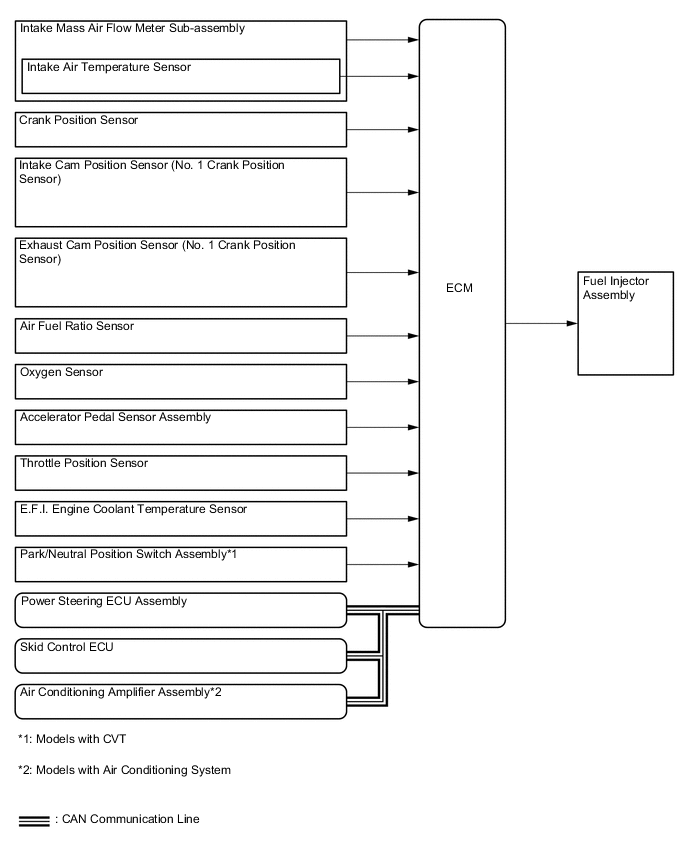
-
Fuel injection is stopped to protect the engine and improve fuel efficiency.
Fuel Cut Fuel Cut Off During Deceleration If the engine speed is above a standard value when decelerating (when the ECM determines that the throttle is off), the fuel injection is stopped to prevent overheating of the catalyst by misfiring, and to improve fuel efficiency. If the coolant temperature is low, the fuel cut speed and restoration speed with be increased. Fuel Cut According to Engine Speed If the engine speed is higher than a standard value, fuel injection is stopped to prevent excessive speed. Fuel Cut When Shifting from "N" to "D"* If the engine speed is higher than a standard value, fuel injection is stopped when the shift lever is operated to protect the CVT. *: Models with CVT
Fuel Cut Speed at High Engine Speed Engine Speed (rpm) 6300
-
-
Electronic Spark Advance (ESA)
-
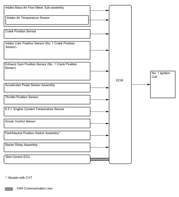
The optimum ignition timing is selected according to signals from the sensors and the ignition signal (IGt) is sent to the igniter.
-
The ignition timing can be expressed using the following equation. The ignition timing is set initially to 10° BTDC.
Ignition Timing = A. Initial Set Ignition Timing or B. Basic Advanced Angle + C. Corrected Advanced Angle A. Fixed Advanced Angle Characteristics Fixed to 5° BTDC when starting the engine. The service terminals are short-circuited, and it is fixed to 10° BTDC when the throttle is closed. B. Basic Advanced Angle Characteristics Selects the optimum ignition timing, depending on each sensor signal. C. Correction Advanced Angle Characteristics Selects the appropriate advanced or retarded angles according to the engine status at that time, depending on each sensor signal. C-1. Warm-up Advanced Angle Characteristics Sets the ignition timing to advanced angle according to the operating status to improve drivability, when the coolant temperature is low. C-2. Idling Stability Advanced Angle Characteristics Sets the ignition timing to advance to stabilize idle speed when the idle speed is low. Also, as the speed gets higher, the ignition timing is retarded. C-3. Knocking Correction Retarded Angle When knocking is generated, the ignition timing is corrected according to a signal from the knock control sensor. -
If engine knocking is detected, the ignition timing is retarded gradually in equal steps according to the size of knocking, until the engine stops knocking.
-
After knocking has stopped, the ignition timing is advanced gradually in equal steps. If the engine knocks again during this process, then the ignition timing is retarded again.
Figure 1. Knocking Feedback Control Cycle

*1 Knocking Occurs *2 Retard *3 Advance *4 No Knocking
-
-
Electronic Throttle Control System-intelligent (ETCS-i)
-
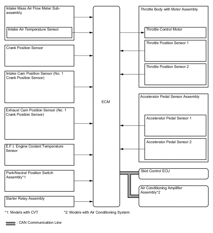
By controlling the engine output optimally for the accelerator pedal opening angle with centralized control using the ECM, good accelerator controllability and vehicle stability are enabled across all speed ranges.
-
Ordinary throttle valve opening angle control (non-linear control) and the idle speed control (ISC) functions have been brought together in the throttle body with motor assembly.
-
By integrated control with the powertrain, superior operability is ensured and comfort is improved.
-
To enable driving in the event of trouble, the system is duplicated to ensure reliability.
ETCS-i Control Driving Control Controls the opening angle of the throttle valve in order to produce engine output in response to the driving conditions and the accelerator pedal opening angle. TRC/VSC Cooperative Control* Stabilizes the vehicle by communicating with the skid control ECU when the TRC and VSC are operating. Idle Speed Control Controls the fast idle speed to suit the engine coolant temperature and the idle speed after the engine is warmed up. In addition, it controls the idle speed in accordance with the fuel injection volume and throttle position. *: Models with brake control system (ABS with EBD, Brake Assist, TRC and VSC)
-
-
Dual Variable Valve Timing-intelligent (VVT-iE and VVT-i)
-
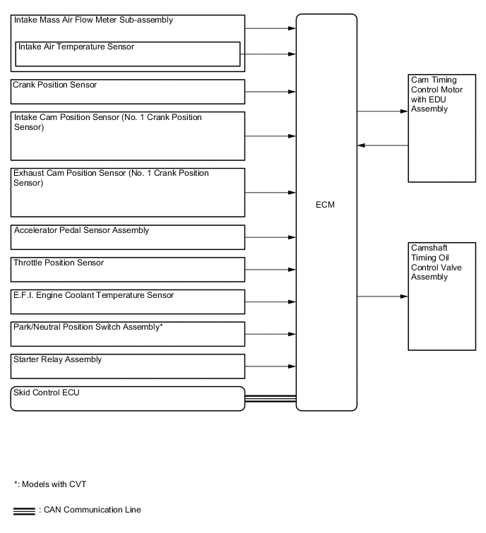
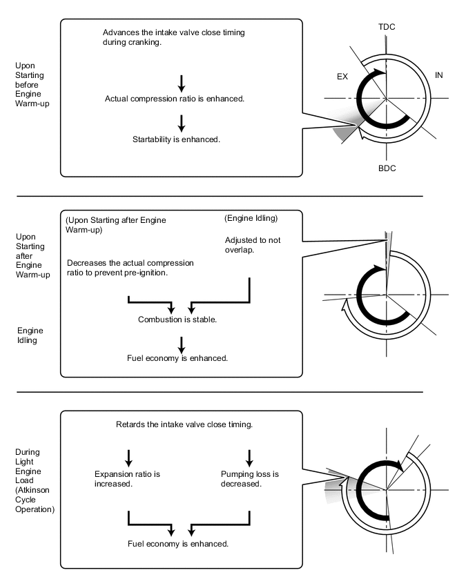
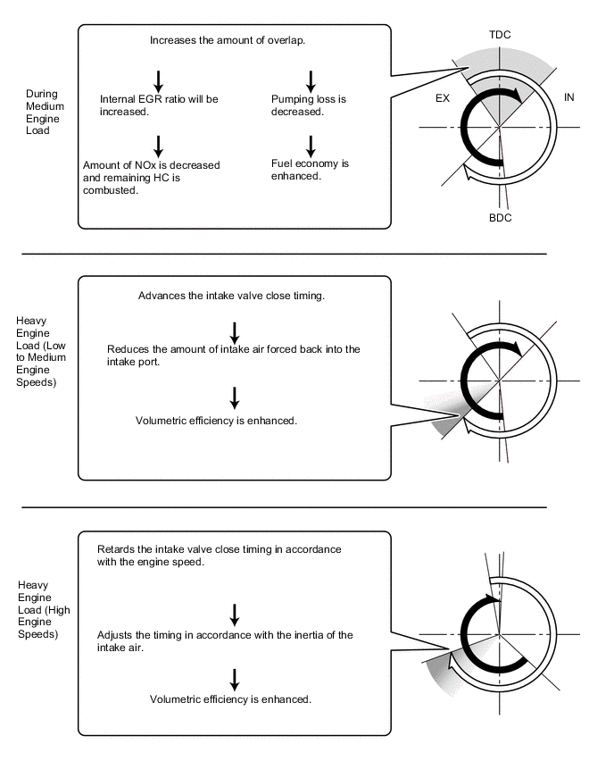
By adopting dual Variable Valve Timing-intelligent (VVT-iE and VVT-i) which can vary the camshaft phase to affect intake and exhaust succession, thus providing high output power with improved fuel efficiency and reduced emissions.
-
Intake valve timing control is by Variable Valve Timing-intelligent by Electric motor (VVT-iE), performed via the cam timing control motor with EDU assembly and camshaft timing gear assembly. Valve timing control via VVT-iE is performed using an electrically driven cam timing control motor with EDU assembly, and so valve timing control does not rely on oil pressure and is performed from the time of engine start.
-
VVT-iE has a wide operating range, and can improve startability of a cold engine by varying intake valve timing toward the advanced side, and shift valve timing towards the retarded side in a warmed-up engine to prevent preignition. Also, when driving at low load, the timing can be set to most retarded to improve fuel efficiency according to the Atkinson cycle.
-
Exhaust valve timing is by Variable Valve Timing-intelligent (VVT-i), performed via the camshaft timing oil control valve assembly and camshaft timing exhaust gear assembly.
-
The ECM, in order to achieve the most suitable valve timing control for the current driving conditions, detects the phase shifts of each camshaft and performs feedback control via the cam position sensor (No. 1 crank position sensor).
-
The VVT-iE and VVT-i systems deliver excellent benefits in vehicle states such as those shown in the illustration below.
-
-
Cooling Fan Control
-
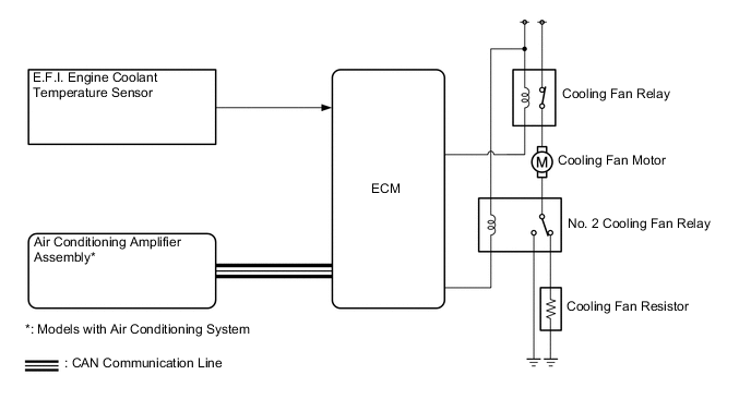
According to the cooling fan drive request signal (low or high) from the air conditioning amplifier assembly and the engine coolant temperature, the ECM regulates the cooling fan speed over 2 levels. A cooling fan drive request signal is determined by the air conditioning amplifier assembly depending on mainly the refrigerant pressure and the A/C switch status.
-
The low speed operation is accomplished by applying the current through a resistor, which reduces the speed of the cooling fan.
Cooling Fan Operation Engine Coolant Temperature Cooling Fan Drive Request Signal Cooling Fan Operation Low Off Off Low Low High High High Off High Low High High High
-
-
Fuel Pump Control
-
In this vehicle, there are 2 types of fuel pump controls. The fuel pump is controlled to an optimum speed to match the engine operating conditions, and the fuel pump operation is stopped when the SRS airbags deploy.
-
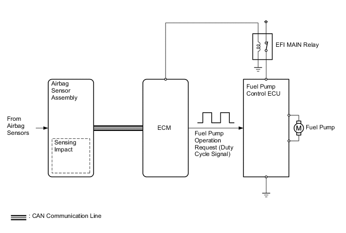
The ECM transmits a fuel pump operation request signal to the fuel pump control ECU that corresponds to the engine operating conditions. The fuel pump control ECU receives this request signal and controls the speed of the fuel pump. As a result, under light engine loads, fuel pump speed is kept low to reduce electric power loss.
-
A fuel cut control is used to stop the fuel pump when the SRS airbags deploy. In this control, if an airbag deployment signal from the airbag sensor assembly is detected by the ECM, the ECM will turn off the EFI MAIN relay. As a result, the power supply to the fuel pump control ECU is stopped, causing the fuel pump to stop operating.
-
The fuel pump control ECU controls fuel pump speed by receiving a duty cycle signal (FPC terminal input) from the ECM.
-
-
-
CONSTRUCTION
-
Air Flow Meter
-
The compact and lightweight plug-in type intake mass air flow meter sub-assembly allows a portion of the intake air to flow through the detection area. By directly measuring the mass and the flow rate of the intake air, the detection precision is improved and the intake air resistance has been reduced.
-
This intake mass air flow meter sub-assembly has a built-in intake air temperature sensor.
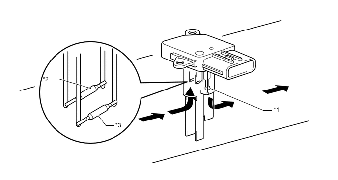
*1 Intake Air Temperature Sensor *2 Hot-wire Element *3 Temperature Sensing Element - - 
Air Flow - -
-
-
Crankshaft Position Sensor and Camshaft Position Sensor
-
Magneto Resistive Element (MRE) type sensors are used for the crank position, intake cam position and exhaust cam position sensors (No. 1 crank position sensors).
-
The timing rotor of the crankshaft has 34 teeth, with 2 teeth missing. Based on these teeth, the crank position sensor transmits crank position signals (NE signal) consisting of 33 high or low output pulses every 10° per revolution of the crankshaft. The ECM uses the NE signal for detecting the crank position as well as for detecting the engine speed. It uses the missing teeth signal for determining the top dead center.
-
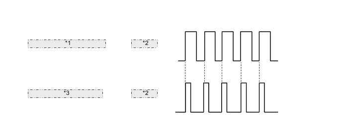
To detect the cam position, a timing rotor on the intake and a timing rotor on the exhaust camshaft are used to generate 3 (3 high output, 3 low output) pulses for every 2 revolutions of the crankshaft.
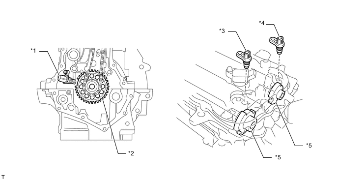
*1 Crank Position Sensor *2 Timing Sprocket *3 Exhaust Cam Position Sensor (No. 1 Crank Position Sensor) *4 Intake Cam Position Sensor (No. 1 Crank Position Sensor) *5 Timing Rotor - - Figure 2. Sensor Output Waveforms
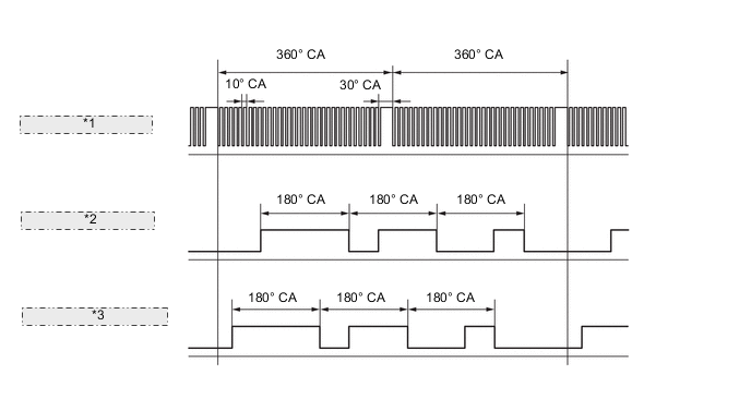
*1 Crank Position Sensor *2 Intake Cam Position Sensor (No. 1 Crank Position Sensor) *3 Exhaust Cam Position Sensor (No. 1 Crank Position Sensor) -
An MRE type sensor consists of an MRE, a magnet and a sensor. The direction of the magnetic field changes due to the profile (protruding and non-protruding portions) of the timing rotor, which passes by the sensor. As a result, the resistance of the MRE changes, and the output voltage to the ECM changes to either high or low. The ECM detects cam position based on this output voltage.
-
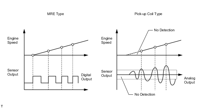
The differences between the MRE type sensor and the pick-up coil type sensor used on a conventional model are as follows.
-
An MRE type sensor outputs a constant level of Hi/Lo digital signals regardless of the engine speed. Therefore, an MRE type sensor can detect the positions of the crankshaft and camshaft at an early stage of cranking.
-
A pick-up coil type sensor outputs analog signals with levels that change with engine speed.
-
-
In order to deliver a smooth engine restart from the engine stop state, the MRE type crank position sensor provided on models with the stop and start system detects crankshaft movements swinging back and forth from the timing rotor rotation direction when the engine has been brought into a stop, helping the ECM determine a more exact crankshaft stop position.
-
The MRE type crank position sensor determines the timing rotor rotation direction from the phase difference between the 2 rectangular wave signals generated by the sensor itself, and then transmits Hi/Lo signals, a short low voltage time when the timing rotor rotates in the normal direction and a long low voltage time when in the reverse direction, to the ECM.
Figure 3. Sensor Output Waveforms
*1 Normal Rotation Direction *2 Ne Signal *3 Reverse Rotation Direction
-
-
Accelerator Pedal Sensor
-
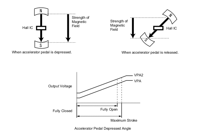
A non-contact type accelerator pedal sensor assembly is used.
-
This sensor uses a Hall IC*1, which can retrieve the strength of the magnetic field as an electrical signal, using the Hall effect*2, in which the output voltage can be directly received in accordance with the accelerator pedal depression amount. When the accelerator pedal depression amount changes, the angle of the magnetic field towards the flow of the current in the Hall IC changes. As a result, the strength of the current and vertical magnetic field changes. Due to this, the change in the voltage generated in the vertical direction towards the forced current and direction of the magnetic field is sent to the ECM as an accelerator pedal depression amount signal. Also, in order to ensure reliability, duplicate sensors (main and sub) with differing sensor output characteristics, are used.
Tech Tips
*1: An electrical component which uses the electromotive force resulting from the potential difference in the magnetic field.
*2: Phenomenon in which a potential difference occurs in the electric current and magnetic field in the vertical direction when a magnetic field in the vertical direction is applied and electric current is flowing through a rod or plated conductor or semiconductor.
-
-
Throttle Position Sensor
-
A non-contact type throttle position sensor is used.
-
This sensor uses a Hall IC*1, which can retrieve the strength of the magnetic field as an electrical signal using Hall effect*2, in which the output voltage can be directly received in accordance with the throttle valve opening angle. When the throttle valve opening angle changes, the angle of the magnetic field towards the flow of the current in the Hall IC changes. As a result, the strength of the current and vertical magnetic field changes. Due to this, the change in the voltage generated in the vertical direction towards the current and direction of the magnetic field is sent to the ECM as a throttle valve opening angle signal. Also, duplicate sensors (main and sub) with differing sensor output characteristics, are used, ensuring reliability.
Tech Tips
*1: An electrical component which uses the electromotive force resulting from the potential difference in the magnetic field.
*2: Phenomenon in which a potential difference occurs in the electric current and magnetic field in the vertical direction when a magnetic field in the vertical direction is applied and electric current is flowing through a rod or plated conductor or semiconductor.
Figure 4. Sensor Output Characteristics
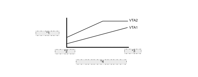
*1 Output Voltage *2 Fully Closed *3 Fully Open *4 Throttle Valve Opening Angle
-
-
Throttle Body
-
A single valve type electronic control throttle body with motor assembly that drives the throttle valve by a motor to ensure excellent driving stability.
-
A DC motor with good response and low power consumption is adopted for the motor for throttle valve drive.
-
Driver operations (the amount of the accelerator pedal being depressed) are transmitted to the ECM by the accelerator pedal sensor assembly provided on the accelerator pedal. The ECM determines the throttle valve opening angle that matches the driving status to drive the throttle control motor. The throttle valve opening angle is fed back to the ECM by the throttle position sensor.
-
When an error is detected, the driver is notified by a warning light in the combination meter assembly and current to the motor is cut. This causes the throttle valve to return to its predetermined angle by the throttle valve return spring. Fuel cut and ignition retard adjust the engine output according to the accelerator pedal opening angle to allow the vehicle to continue at a minimal speed.
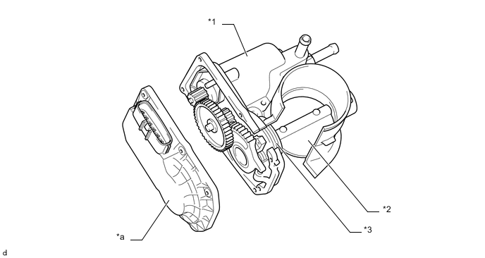
*1 Throttle Control Motor *2 Throttle Valve *3 Return Spring - - *a Throttle Position Sensor Portion - -
-
-
Camshaft Control Motor
-
The cam timing control motor with EDU assembly consists of a motor that operates the camshaft timing gear assembly in the advance or retard direction, an Electronic Driver Unit (EDU) that controls the rotation of the motor, and a Hall IC type rotation sensor that detects the rotation of the motor.
-
The motor is a brushless type DC motor that is installed in the timing chain cover assembly forward of the camshaft timing gear assembly. It rotates coaxially with the intake camshaft.
-
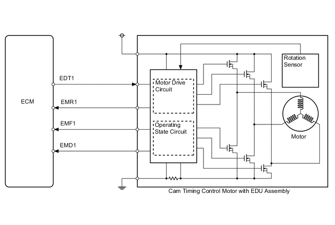
In accordance with the target valve timing, the ECM transmits the motor speed and direction of rotation instruction signals to the EDU. Based on those signals, the EDU drives the motor to advance or retard the timing of the intake camshaft.
-
The EDU always monitors the operation of the motor, and transmits the actual motor speed, direction of rotation, and the state of operation signals to the ECM. The ECM uses these signals to diagnose malfunctions.
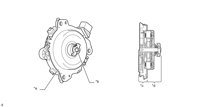
*a Timing Chain Cover Fixed Surface *b Camshaft Timing Gear Assembly Fitting Portion *c Motor Driver (EDU) Portion *d Brushless Type DC Motor Portion Figure 5. Circuit Diagram
-
-
Camshaft Timing Oil Control Valve
-
The camshaft timing oil control valve assembly controls the spool valve using duty cycle control from the ECM. This allows engine oil pressure to be applied to the camshaft timing exhaust gear assembly advance or retard side. When the engine is stopped, the camshaft timing oil control valve assembly is in the most advanced position.
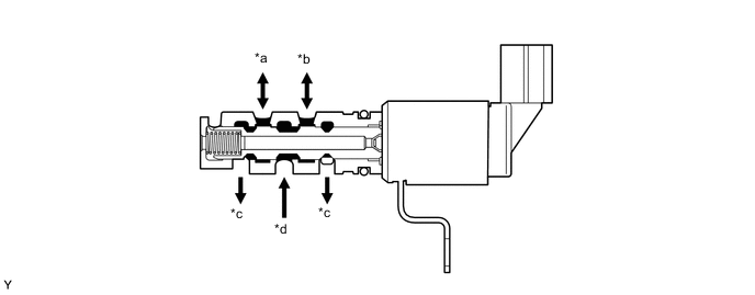
*a To Camshaft Timing Exhaust Gear Assembly (Retard Side) *b To Camshaft Timing Exhaust Gear Assembly (Advance Side) *c Drain *d Oil Pressure
-
-
Water Temperature Sensor
-
This sensor detects the engine coolant temperature. A thermistor whose resistance value greatly changes according to the temperature is built-in. Changes in the coolant temperature are detected by the changes in the thermistor resistance value.
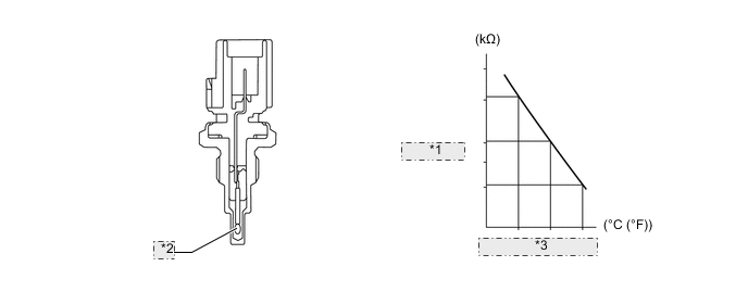
*1 Resistance *2 Thermistor *3 Coolant Temperature
-
-
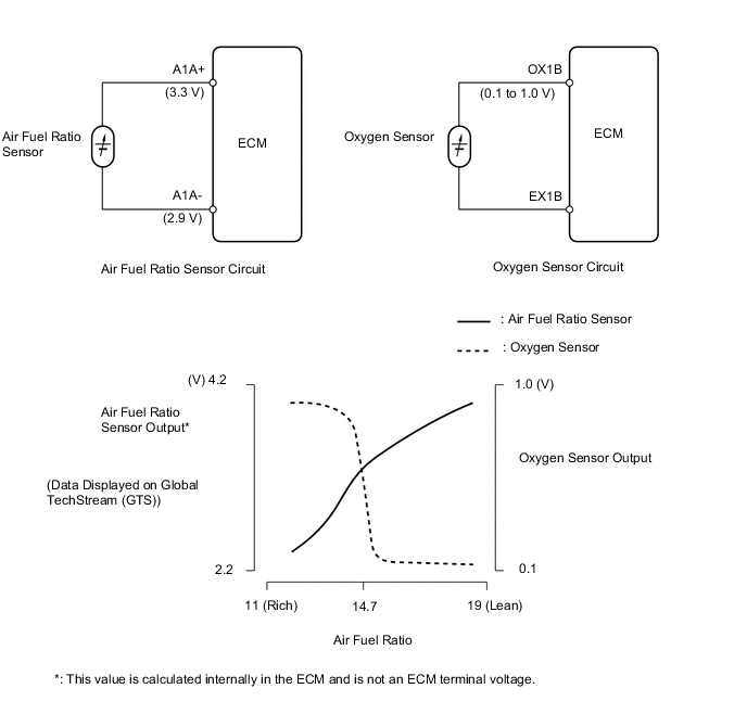
Oxygen Sensor and Air Fuel Ratio Sensor
-
The oxygen sensor and the air fuel ratio sensor differ in output characteristics.
-
The output voltage of the oxygen sensor changes in accordance with the oxygen concentration in the exhaust gas. The ECM uses this output voltage to determine whether the present air fuel ratio is richer or leaner than the stoichiometric air fuel ratio.
-
Approximately 0.4 V is constantly applied to the air fuel ratio sensor, which outputs an amperage that varies in accordance with the oxygen concentration in the exhaust gas. The ECM converts the changes in the output amperage into voltage in order to linearly detect the present air fuel ratio.
-
The basic construction of the oxygen sensor and the air fuel ratio sensor is the same. However, they are divided into the cup type and the planar type, according to the different types of heater construction that are used.
-
The cup type sensor contains a sensor element that surrounds a heater.
-
The planar type sensor uses alumina, which excels in heat conductivity and insulation, to integrate a sensor element with a heater, thus improving the warm up performance of the sensor.
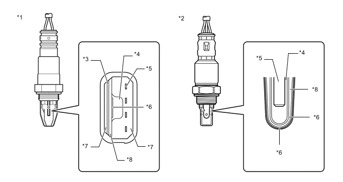
*1 Air Fuel Ratio Sensor (Planar Type) *2 Oxygen Sensor (Cup Type) *3 Diffusion Resistance Layer *4 Atmosphere *5 Heater *6 Platinum Electrode *7 Alumina *8 Sensor Element (Zirconia)
-
-
Knock Control Sensor
-
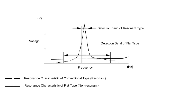
In a conventional knock control sensor (resonant type), a vibration plate is built into the sensor. This plate has the same resonance point as the knocking frequency of the engine block. This sensor can only detect vibration in this frequency band.
-
A flat type knock control sensor (non-resonant type) has the ability to detect vibration in a wider frequency band (from about 5 kHz to 15 kHz). It has the following features.
-
The engine knocking frequency will vary slightly depending on the engine speed. The flat type knock control sensor can detect vibration even when the engine knocking frequency changes. Due to the use of the flat type knock control sensor, the vibration detection ability is increased compared to a conventional type knock control sensor, and more precise ignition timing control is possible.
Figure 6. Characteristics of Knock Control Sensor
-
A flat type knock control sensor is installed to an engine by placing it over the stud bolt installed on the cylinder block sub-assembly. For this reason, a hole for the stud bolt exists in the center of the sensor.
-
In the sensor, a steel weight is located in the upper portion. An insulator is located between the weight and a piezoelectric element.
-
An open/short circuit detection resistor is integrated in the sensor. When the ignition is ON, the open/short circuit detection resistor in the knock control sensor and the resistor in the ECM keep the voltage at terminal KNK1 constant. An Integrated Circuit (IC) in the ECM constantly monitors the voltage of terminal KNK1. If the open/short circuit occurs between the knock control sensor and the ECM, the voltage of terminal KNK1 will change and the ECM will detect the open/short circuit and store a Diagnostic Trouble Code (DTC).
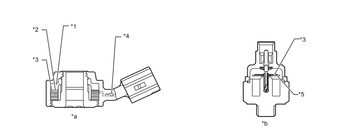
*1 Steel Weight *2 Insulator *3 Piezoelectric Element *4 Open/Short Circuit Detection Resistor *5 Vibration Plate - - *a Flat Type Knock Control Sensor (Non-resonant Type) *b Conventional Type Knock Control Sensor (Resonant Type) 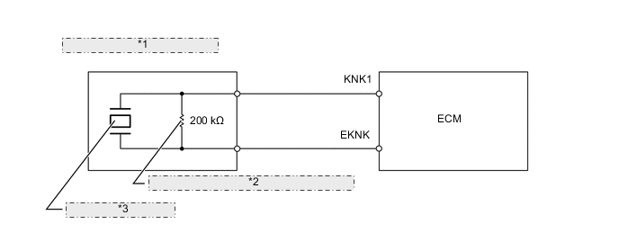
*1 Flat Type Knock Control Sensor *2 Open/Short Circuit Detection Resistor *3 Piezoelectric Element -
Vibrations caused by knocking are transmitted to the steel weight. The inertia of this weight applies pressure to the piezoelectric element. This action generates electromotive force.

*1 Steel Weight *2 Piezoelectric Element Inertia - -
-
-
Ignition Coil
-
An igniter is integrated with the ignition coils, which are provided independently in each cylinder. This improves ignition timing accuracy, reduces high-voltage loss and enhances the overall reliability of the ignition system by eliminating the distributor.
-
The spark plug caps, which provide contact to spark plugs, are integrated with a No. 1 ignition coil. Also, an igniter is enclosed to simplify the system.
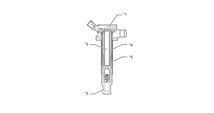
*1 Igniter *2 Iron Core *3 Spark Plug Cap *4 Secondary Coil *5 Primary Coil - -
-
-
Spark Plug
-
Long-reach type, narrow-diameter spark plugs with iridium central electrodes are used.
-
By using needle-needle type electrodes, ignitability is improved, and with their heat index of 16, they are effective against carbon fouling.
-
Because iridium offers an extremely high level of wear resistance, the central electrode could be made thinner, and more reliable ignition is achieved. In addition, the improved wear resistance of the center electrode offers longer operational life and so improves maintainability.
-
By narrowing the diameter of the threaded portion of the spark plug and changing to a long-reach type, the water jacket around the spark plug was optimized and the cooling ability of the cylinder head sub-assembly was improved.
Tech Tips
Because the plug size differs from that of normal spark plugs, be careful not to use the wrong tools during installation/removal procedures.
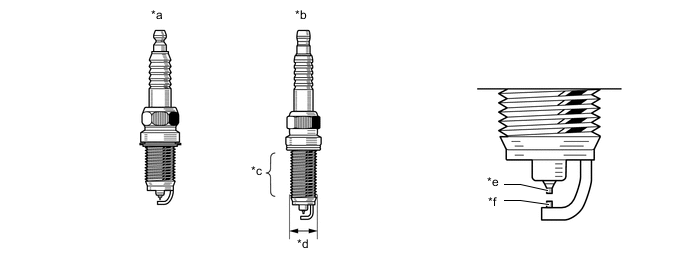
*a Conventional Type *b Long-reach Narrow-diameter Type *c Long-reach *d Narrow-diameter Portion *e Iridium Tip *f Platinum Tip
-
-
-
OPERATION
-
Camshaft Control Motor
-
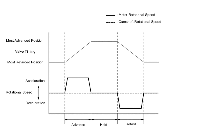
The ECM controls the advance and retard operation by way of the rotational speed difference between the motor and the camshaft. The ECM maintains the valve timing by rotating the motor at the same rotational speed as the camshaft.
-
To advance, the motor rotational speed becomes faster than the camshaft rotational speed.
-
To retard, the motor rotational speed becomes slower than the camshaft rotational speed. (The motor turns clockwise and counterclockwise in accordance with engine conditions.)
Figure 7. Relationship between Motor Rotational Speed and Advance and Retard Timing
-
-
-
-
FAIL-SAFE
-
When the ECM detects a malfunction, the ECM stops or controls the engine according to the data already stored in the memory. For details, refer to the Repair Manual.
-
-
DIAGNOSIS
-
When the ECM detects a malfunction, the ECM diagnoses and memorizes the failed section. For details, refer to the Repair Manual.
-