SFI SYSTEM
-
FUNCTION OF MAIN COMPONENTS
-
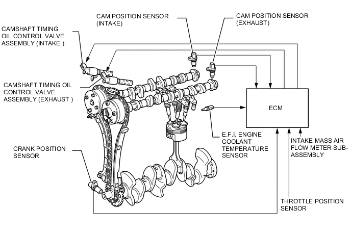
The main components of the 1NR-FE engine control system are as follows.
Components Outline Quantity Function ECM 32-bit CPU 1 The ECM optimally controls the SFI, ESA, and ETCS-i to suit the operating conditions of the engine in accordance with the signals provided by the sensors. Crank Position Sensor (Rotor Teeth) Magnetic Resistance Element (MRE) Type (36 - 2) 1 This sensor detects the engine speed and performs cylinder identification. Cam Position Sensor (Rotor Teeth) Magnetic Resistance Element (MRE) Type (3) 2 This sensor performs cylinder identification. Knock Control Sensor Built-in Piezoelectric Element Type (Flat Type) 1 This sensor detects an occurrence of the engine knocking indirectly from the vibration of the cylinder block caused by the occurrence of engine knocking. Intake Mass Air Flow Meter Sub-assembly Hot-wire Type 1 This sensor uses a built-in hot-wire to directly detect the intake air mass. Throttle Position Sensor Non-contact Type 1 This sensor detects the throttle valve opening angle. Oxygen Sensor Cup Type with Heater 1 This sensor detects the oxygen concentration in the exhaust emission by measuring the electromotive force which is generated in the sensor itself. Air Fuel Ratio Sensor Planar Type with Heater 1 As with the oxygen sensor, this sensor detects the oxygen concentration in the exhaust gas. However, it detects the oxygen concentration in the exhaust gas linearly. Accelerator Pedal Sensor Assembly Non-contact Type 1 This sensor detects the amount of pedal effort applied to the accelerator pedal. E.F.I. Vacuum sensor Assembly Semiconductor Silicon Chip Type 1 This sensor uses built-in semiconductors to detect the intake manifold pressure. Fuel Injector Assembly 8-hole Type 4 The fuel injector is an electromagnetically-operated solenoid with a nozzle which injects fuel in accordance with signals from the ECM. E.F.I. Engine Coolant Temperature Sensor Thermistor Type 1 This sensor detects the water temperature by means of an internal thermistor.
-
-
SYSTEM CONTROL
-
The engine control system of the 1NR-FE engine has the following systems.
Components Function Sequential multiport Fuel Injection (SFI) An L-type SFI system is used, the intake air mass is detected with a hot-wire type air flow meter. The fuel injection system is a sequential multiport fuel injection system. Electronic Spark Advance (ESA) The ECM determines the optimal ignition timing in accordance with the signals received from the sensors and sends (IGT) ignition signal to the igniter. The ECM corrects ignition timing in response to engine knocking. Electronic Throttle Control System-intelligent (ETCS-i) Optimally controls the throttle valve opening in accordance with the amount of accelerator pedal effort, the throttle valve opening control request from the ECM, and the condition of the engine and the vehicle. Dual Variable Valve Timing-intelligent (VVT-i) Regulates operation of the intake and exhaust camshafts to ensure optimal valve timing in accordance with engine operating conditions. Fuel Pump Control Fuel pump operation is controlled by signals from the ECM. The fuel pump is stopped when the SRS airbags deploy. Cooling Fan Control Cooling fan operation is controlled by signals from the ECM based on the E.F.I. engine coolant temperature sensor signal. Early Stage Injection Control*1 The ECM calculates appropriate injection and ignition at an early stage. The ECM uses these calculated values when the engine is stopped due to stop and start system control. Stopping Position Control*2 While the engine stopping operation is performed, the ECM uses ignition timing and generator load torque to control the crankshaft position at the time when the engine is stopped. The ECM always positions the crankshaft at the optimal position. This shortens the time necessary to start the engine. Starter Control*3 (Cranking Hold Function) On the models with entry and start system, once the engine switch is pushed, this control continues to operate the starter until the engine is started. Air Fuel Ratio Sensor and Oxygen Sensor Heater Control Maintains the temperature of the air fuel ratio sensors or oxygen sensors at an appropriate level to increase the detection accuracy of the exhaust gas oxygen concentration. Engine Immobiliser Prohibits fuel delivery and ignition if an attempt is made to start the engine with an invalid key. Air Conditioning Cut-off Control*4 By turning the air conditioning compressor on or off in accordance with engine operating conditions, drivability is maintained. Brake Override System Restricts the driving torque when both the accelerator and brake pedals are depressed. (For the Activation Conditions and Inspection Method, refer to the repair manual)
-
*1: Models with stop and start system
-
*2: M/T models with stop and start system
-
*3: Models with entry and start system
-
*4: Models with air conditioning system
-
-
Dual Variable Valve Timing-intelligent (VVT-i) System
-
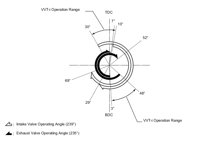
The Dual VVT-i system is designed to control the intake and exhaust camshafts within a range of 50° and 45° respectively (of crankshaft angle) to provide valve timing that is optimally suited to engine operating conditions. This improves torque in all speed ranges as well as increasing fuel economy and reducing exhaust emissions.
-
The Dual VVT-i system delivers excellent benefit vehicle states as shown in the table below.
Operation State Objective Effect During Idle 
*1 TDC *2 Most Retarded *3 BDC Eliminating overlap to reduce blow back to the intake side.
-
Stabilized idle speed
-
Better fuel economy
At Light Load 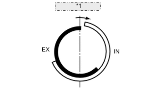
*1 To Retarded Side Eliminating overlap to reduce blow back to the intake side. Ensured engine stability is ensured At Medium Load 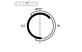
*1 To Advanced Side Increasing overlap to increase internal EGR to reduce pumping losses.
-
Better fuel economy
-
Improved emission control
In Low to Medium Speed Range with Heavy Load 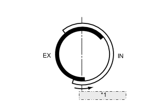
*1 To Advanced Side Advancing the intake valve close timing for volumetric efficiency improvement. Improved torque in low to medium speed range In High Speed Range with Heavy Load 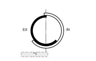
*1 To Retarded Side Retarding the intake valve close timing for volumetric efficiency improvement Improved output At Low Temperatures 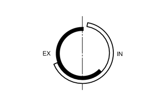
Eliminating overlap to reduce blow back to the intake side stabilizes the idle speed during fast idle.
-
Stabilized idle rpm
-
Better fuel economy
-
Upon Starting the Engine
-
Upon Stopping the Engine
*1 Most Retarded Eliminating overlap to minimize blow back to the intake side. Improved startability -
-
-
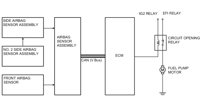
Fuel Pump Control
-
In this system, the airbag deployment signal from the airbag sensor assembly is detected by the ECM, and it turns off the circuit opening relay. After the fuel cut control has been activated, turning the power source from off to on or selecting the ignition switch from off to on mode cancels the fuel cut control, and the engine can be restarted.
-
-
Cooling Fan Control
-
A cooling fan control system controlled to achieve an optimal fan speed in accordance with the engine coolant temperature and air conditioning operating conditions.
-
-
-
CONSTRUCTION
-
ECM
-
The ECM is installed in the engine compartment. As a result, the wiring harness has been shortened, thus realizing weight reduction.
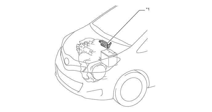
Text in Illustration *1 ECM - -
-
-
Crank Position and Cam Position Sensors
-
Magnetic Resistance Element (MRE) type sensors are used for the crank position, intake cam position and exhaust cam position sensors.
-
The timing Rotor of the crankshaft has 34 teeth, with 2 teeth missing. Based on these teeth, the crank position sensor transmits crank position signals (NE signal) consisting of 33 high or low output pulses every 10° per revolution of the crankshaft. The ECM uses the NE signal for detecting the crank position as well as for detecting the engine speed. It uses the missing teeth signal for determining the top dead center.
-
To detect the cam position, a timing rotor on the intake and a timing rotor on the exhaust camshaft are used to generate 3 (3 high output, 3 low output) pulses for every 2 revolutions of the crankshaft.
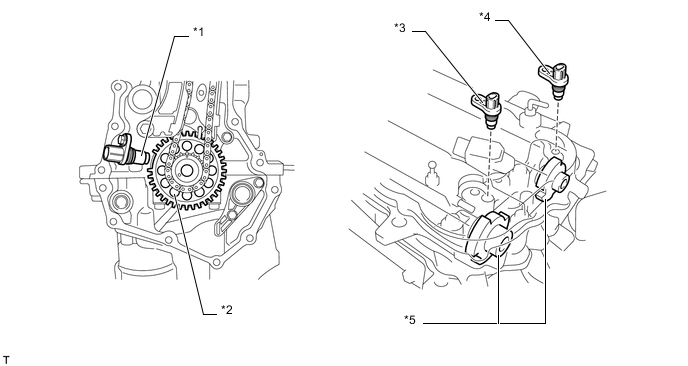
Text in Illustration *1 Crank Position Sensor *2 Timing Sprocket *3 Cam Position Sensor (Exhaust) *4 Cam Position Sensor (Intake) *5 Timing Rotor - - 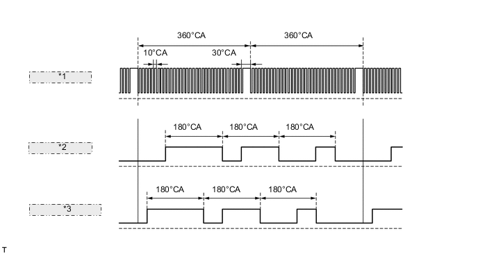
Sensor Output Waveforms *1 Crank Position Sensor *2 Cam Position Sensor (Intake) *3 Cam Position Sensor (Exhaust) -
An MRE type sensor consists of an MRE, a magnet and a sensor. The direction of the magnetic field changes due to the profile (protruding and non-protruding portions) of the timing rotor, which passes by the sensor. As a result, the resistance of the MRE changes, and the output voltage to the ECM changes to either high or low. The ECM detects cam position based on this output voltage.
-
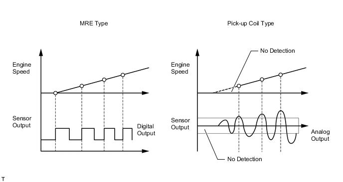
The differences between the MRE type sensor and the pick-up coil type sensor used on a conventional model are as follows.
-
An MRE type sensor outputs a constant level of Hi/Lo digital signals regardless of the engine speed. Therefore, an MRE type sensor can detect the positions of the crankshaft and camshaft at An early stage of cranking.
-
A pickup coil type sensor outputs analog signals with levels that change with engine speed.
-
-
In order to deliver a smooth engine restart from the engine stop state, the MRE type crank position sensor provided on models with the stop and start system detects crankshaft movements swinging back and forth from the timing rotor rotation direction when the engine has been brought into a stop, helping the ECM determine a more exact crankshaft stop position.
-
The MRE type crank position sensor determines the timing rotor rotation direction from the phase difference between the 2 rectangular wave signals generated by the sensor itself, and then transmits Hi/Lo signals, a short low voltage time when the timing rotor rotates in the normal direction and a long low voltage time when in the reverse direction, to the ECM.
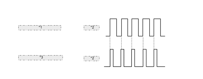
Sensor Output Waveforms *1 Normal rotation direction *2 Ne signal *3 Reverse rotation direction
-
-
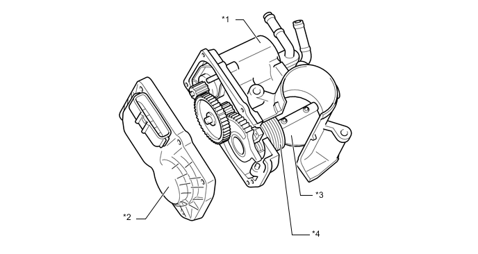
Camshaft Timing Oil Control Valve Assembly
-
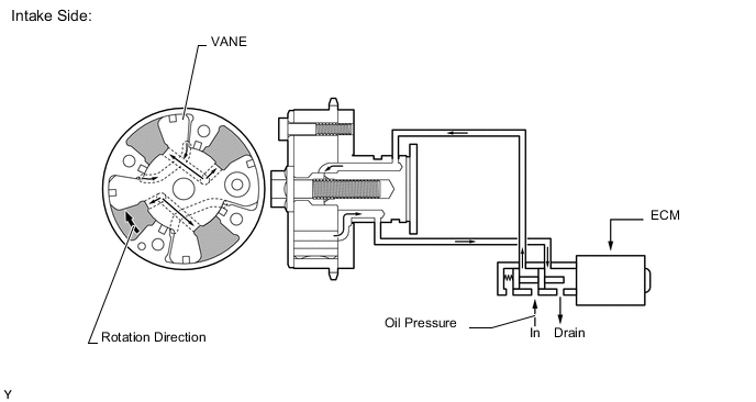
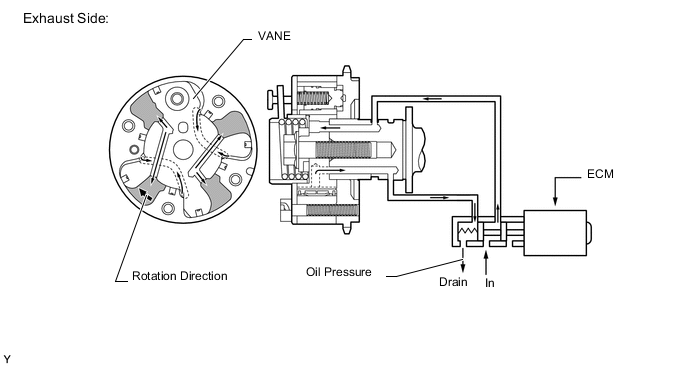
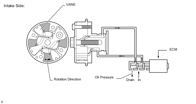
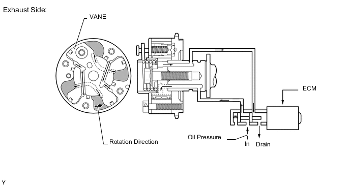
This camshaft timing oil control valve assembly controls the spool valve using duty cycle control from the ECM. This allows hydraulic pressure to be applied to the VVT-i controller advance or retard side. When the engine is stopped, the intake camshaft timing oil control valve assembly will move to the retard position, and the exhaust camshaft timing oil control valve assembly will move to the advance position.
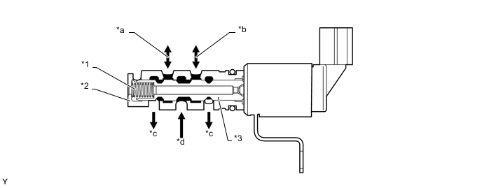
Text in Illustration (Camshaft Timing Oil Control Valve Assembly (Intake):) *1 Spring *2 Sleeve *3 Spool Valve - - *a To Intake VVT-i Controller (Advance Side) *b To Intake VVT-i Controller (Retard Side) *c Drain *d Oil Pressure 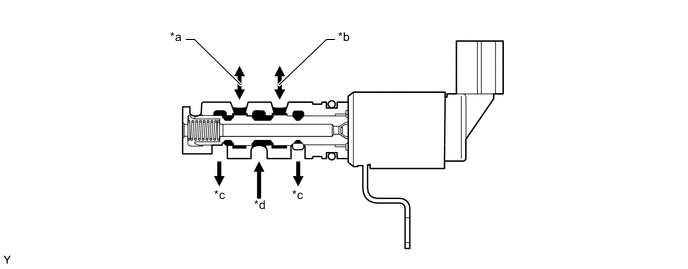
Text in Illustration (Camshaft Timing Oil Control Valve Assembly (Exhaust):) *a To Exhaust VVT-i Controller (Retard Side) *b To Exhaust VVT-i Controller (Advance Side) *c Drain *d Oil Pressure
-
-
Knock Control Sensor (Flat Type)
-
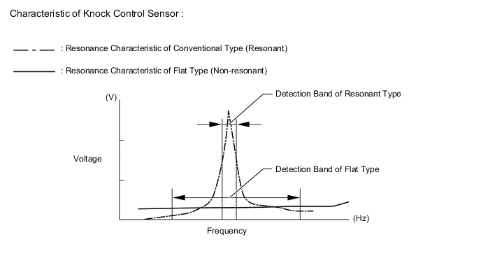
In a conventional knock control sensor (resonant type), a vibration plate is built into the sensor. This plate has the same resonance point as the knocking frequency of the engine block. This sensor can only detect vibration in this frequency band.
-
A flat type knock control sensor (non-resonant type) has the ability to detect vibration in a wider frequency band (from about 6 kHz to 15 kHz). It has the following features.
-
The engine knocking frequency will vary slightly depending on the engine speed. The flat type knock control sensor can detect vibration even when the engine knocking frequency changes. Due to the use of the flat type knock control sensor, the vibration detection ability is increased compared to a conventional type knock control sensor, and more precise ignition timing control is possible.
-
A flat type knock control sensor is installed to an engine by placing it over the stud bolt installed on the cylinder block sub-assembly. For this reason, a hole for the stud bolt exists in the center of the sensor.
-
In the sensor, a steel weight is located in the upper portion. An insulator is located between the weight and a piezoelectric element.
-
An open/short circuit detection resistor is integrated in the sensor. When the ignition is ON, the open/short circuit detection resistor in the knock control sensor and the resistor in the ECM keep the voltage at terminal KNK1 constant. An Integrated Circuit (IC) in the ECM constantly monitors the voltage of terminal KNK1. If the open/short circuit occurs between the knock control sensor and the ECM, the voltage of terminal KNK1 will change and the ECM will detect the open/short circuit and store a Diagnostic Trouble Code (DTC).
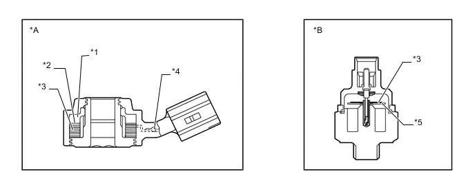
Text in Illustration *A Flat Type Knock Control Sensor (Non-Resonant Type) *B Conventional Type Knock Control Sensor (Resonant Type) *1 Steel Weight *2 Insulator *3 Piezoelectric Element *4 Open Circuit Detection Resistor *5 Vibration Plate - - 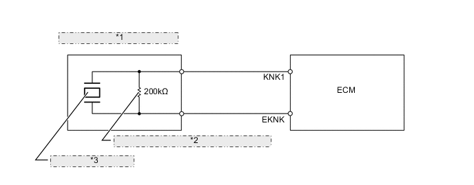
*1 Flat Type Knock Control Sensor *2 Open/Short Circuit Detection Resistor *3 Piezoelectric Element -
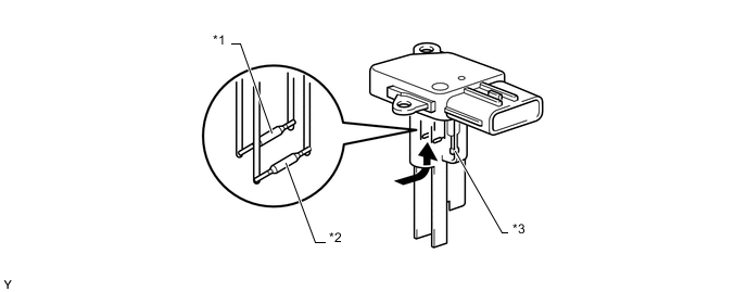
Vibrations caused by knocking are transmitted to the steel weight. The inertia of this weight applies pressure to the piezoelectric element. This action generates electromotive force.

Text in Illustration *1 Steel Weight *2 Piezoelectric Element 
Inertia - -
-
-
Intake Mass Air Flow Meter Sub-assembly
-
This compact and lightweight plug-in type intake mass air flow meter sub-assembly allows a portion of the intake air to flow through the detection area. By directly measuring the mass and the flow rate of the intake air, the detection precision is improved and the intake air resistance has been reduced.
-
This intake mass air flow meter sub-assembly has a built-in intake air temperature sensor.
Text in Illustration *1 Hot-wire Element *2 Temperature Sensing Element *3 Intake Air Temperature Sensor - - Air Flow - -
-
-
Throttle Position Sensor
-
The throttle position sensor is mounted on the throttle body to detect the opening angle of the throttle valve. The throttle position sensor converts the magnetic flux density that changes when the magnetic yoke (located on the same axis as the throttle shaft) rotates around the Hall IC into electric signals to operate the throttle control motor.
Text in Illustration *1 Throttle Control Motor *2 Throttle Position Sensor *3 Throttle Valve *4 Return Spring 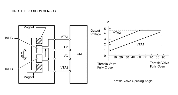
-
-
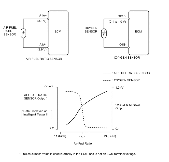
Oxygen Sensor and Air Fuel Ratio Sensor
-
The oxygen sensor and the air fuel ratio sensor differ in output characteristics.
-
The output voltage of the heated oxygen sensor changes in accordance with the oxygen concentration in the exhaust gas. The ECM uses this output voltage to determine whether the present air fuel ratio is richer or leaner than the stoichiometric air fuel ratio.
-
Approximately 0.4 V is constantly applied to the air fuel ratio sensor, which outputs an amperage that varies in accordance with the oxygen concentration in the exhaust gas. The ECM converts the changes in the output amperage into voltage in order to linearly detect the present air fuel ratio.
-
The basic construction of the heated oxygen sensor and the air fuel ratio sensor is the same. However, they are divided into the cup type and the planar type, according to the different types of heater construction that are used.
-
The cup type sensor contains a sensor element that surrounds a heater.
-
The planar type sensor uses alumina, which excels in heat conductivity and insulation, to integrate a sensor element with a heater, thus improving the warm up performance of the sensor.
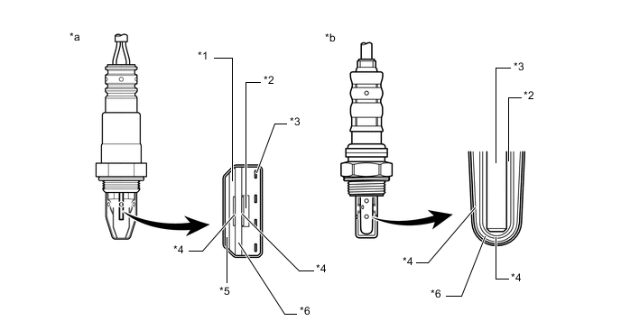
Text in Illustration *1 Diffusion Resistance Layer *2 Atmosphere *3 Heater *4 Platinum Electrode *5 Alumina *6 Sensor Element (Zirconia) *a Air Fuel Ratio Sensor (Planar Type) *b Oxygen Sensor (Cup Type)
-
-
Accelerator Pedal Sensor Assembly
-
The non-contact type accelerator pedal sensor assembly uses a Hall IC.
-
The magnetic yoke that is mounted at the accelerator pedal arm rotates around the Hall IC in accordance with the amount of effort that is applied to the accelerator pedal. The Hall IC converts the changes in the magnetic flux that occur at that time into electrical signals, and outputs them as accelerator pedal effort to the ECM.
-
The Hall IC contains circuits for the main and sub signals. It converts the accelerator pedal depressed angles into electric signals with two differing characteristics and outputs them to the ECM.
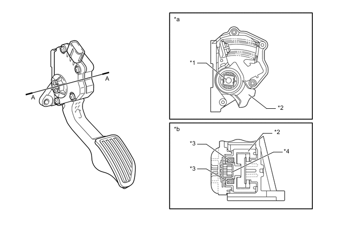
Text in Illustration *1 Magnetic Yoke *2 Accelerator Pedal Arm *3 Magnet *4 Hall IC *a Internal Construction *b A-A Cross Section 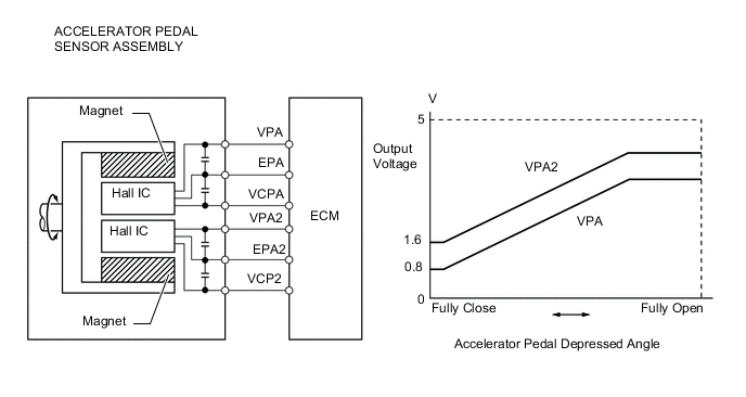
-
-
No. 1 Ignition Coil
-
An igniter is integrated with the ignition coils, which are provided independently in each cylinder. This improves ignition timing accuracy, reduces high-voltage loss and enhances the overall reliability of the ignition system by eliminating the distributor.
-
The spark plug caps, which provide contact to spark plugs, are integrated with a No. 1 ignition coil. Also, an igniter is enclosed to simplify the system.
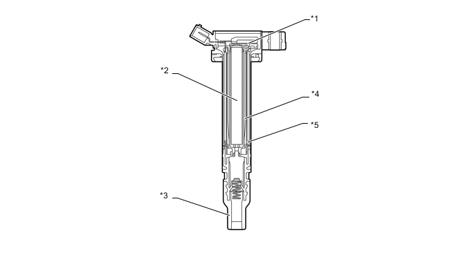
Text in Illustration *1 Igniter *2 Iron Core *3 Spark Plug Cap *4 Secondary Coil *5 Primary Coil - -
-
-
Spark Plug
-
Long-reach, thin-electrode type iridium-tipped spark plugs are used. This type of spark plugs allows the area of the cylinder head to receive the spark plugs to be made thick. Thus, the water jacket can be extended near the combustion chamber, which contributes to cooling performance.
-
Iridium-tipped spark plugs improve ignition performance while maintaining the same durability as platinum-tipped spark plugs.
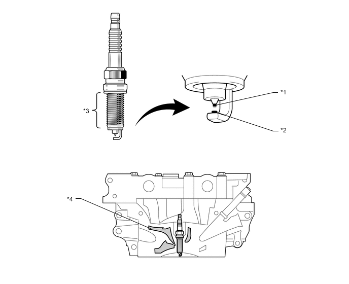
Text in Illustration *1 Iridium Tip *2 Platinum Tip *3 Long-reach *4 Water Jacket
-
-
-
OPERATION
-
Dual Variable Valve Timing-intelligent (VVT-i) System
-
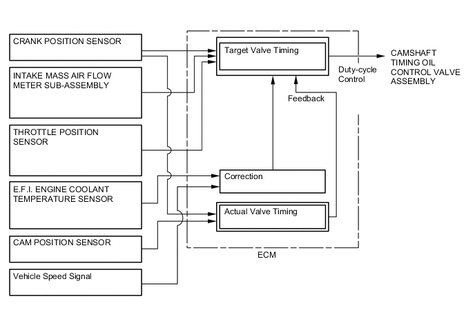
Using the engine speed, intake air mass, throttle position and water temperature, the ECM can calculate optimal valve timing for each driving condition (target valve timing). The ECM uses this calculated timing to control the camshaft timing oil control valves. In addition, the ECM uses signals from the camshaft position sensors and the crank position sensor to detect the actual valve timing, thus providing feedback control to achieve the target valve timing.
-
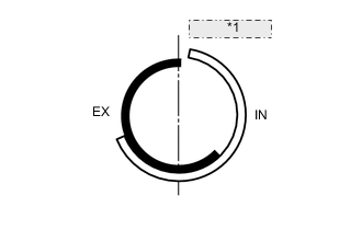
When the camshaft timing oil control valve is operated as illustrated below by the advance signal from the ECM, the resultant oil pressure is applied to the timing advance side vane chamber to rotate the camshaft in the timing advance direction.
-
When the camshaft timing oil control valve is operated as illustrated below by the retard signal from the ECM, the resultant oil pressure is applied to the timing retard side vane chamber to rotate the camshaft in the timing retard direction.
-
After reaching the target timing, the valve timing is held by keeping the camshaft timing oil control valve assembly in the neutral position unless the traveling state changes. This adjusts the valve timing at the desired target position and prevents the engine oil from running out when it is unnecessary.
-
-
Fuel Pump Control
-
The fuel pump control is used to stop the fuel pump when the airbags deploy in a front or side collision.
-
In this system, when the airbag deployment signal from the airbag sensor assembly is detected by the ECM, the ECM turns off the circuit opening relay.
-
After the fuel cut control has been activated, turning the ignition switch from off to ON cancels the fuel cut control, and the engine can be restarted.
-
-
Cooling Fan Control
-
According to the cooling fan drive request signal (low or high) from the air conditioning amplifier assembly and the engine coolant temperature, the ECM regulates the cooling fan speed over 2 levels. A cooling fan drive request signal is determined by the air conditioning amplifier assembly depending on mainly the refrigerant pressure and the A/C switch status.
-
The Low speed operation is accomplished by applying the current through a resistor, which reduces the speed of the cooling fan.
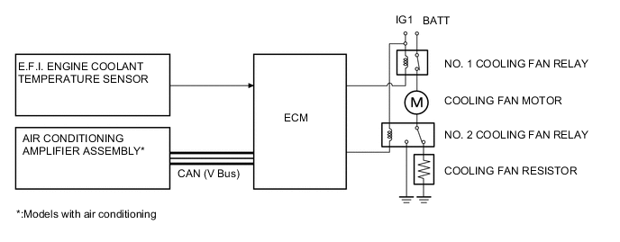
Engine Coolant Temperature Cooling Fan Drive Request Signal Cooling Fan Operation Low Off Off Low Low High High High Off High Low High High High
-
-
-
FAIL-SAFE
-
When the ECM detects a malfunction, the ECM stops or controls the engine according to the data already stored in the memory. For details, refer to the Repair Manual.
-
-
DIAGNOSIS
-
When the ECM detects a malfunction, the ECM diagnoses and memorizes the failed section. For details, refer to the Repair Manual.
-