SFI SYSTEM
-
FUNCTION OF MAIN COMPONENTS
-
The main components of the 1ND-TV engine control system are as follows:
Components Outline Quantity Function ECM 32-bit CPU 1 The ECM effects overall control of the engine control system to suit the operating conditions of the engine in accordance with the signals provided by the sensors. The atmospheric pressure sensor built into the ECM measures the atmospheric pressure. Atmospheric Temperature Sensor Thermistor Type 1 This sensor is built into the air flow meter, detects the atmospheric temperature by means of an internal thermistor. Intake Mass Air Flow Meter Sub-assembly Hot-wire Type (Digital Signal Type) 1 This sensor has a built-in hot-wire to directly detect the intake air mass and flow rate. Crank Position Sensor (Rotor Teeth) Pickup Coil Type (60-2) 1 This sensor detects the engine speed and performs the cylinder identification. Cam Position Sensor (Rotor Teeth) Pick-up Coil Type (1) 1 This sensor performs the cylinder identification. Diesel Engine Engine Coolant Temperature Sensor Thermistor Type 1 This sensor detects the engine coolant temperature by means of an internal thermistor. Accelerator Pedal Sensor Assembly Non-contact Type 1 This sensor detects the amount of pedal effort applied to the accelerator pedal. Throttle Position Sensor Non-contact Type 1 This sensor is built into throttle body, detects the throttle valve opening angle. Injector Assembly Piezo Type (7-hole Type) 4 The injector injects fuel by vertically driving the nozzle needle after activating the piezo actuator based on signals from the ECM. Turbo Pressure Sensor Semiconductor Silicon Chip Type 1 This sensor uses built-in semiconductors to detect the intake manifold pressure. Intake Air Temperature Sensor Thermistor Type 1 This sensor detect the intake air temperature after the intercooler. Fuel Pressure Sensor Semiconductor Strain Gauge Type 1 This sensor uses built-in semiconductors to detect the internal pressure of the common-rail. Fuel Temperature Sensor Thermistor Type 1 This sensor detects the fuel temperature in the supply pump by means of an internal thermistor. Engine Oil Level Sensor ON/OFF Switch Type 1 This sensor detects the oil level via the oil upper level switch and the oil lower level switch.
-
-
SYSTEM CONTROL
-
The engine control system of the 1ND-TV engine has the following systems.
System Outline Fuel Injection Volume Control Based on the signals received from the various sensors, the ECM determines the fuel injection volume in accordance with the engine condition. Fuel Injection Timing Control Based on the signals received from the various sensors, the ECM determines the fuel injection timing in accordance with the engine condition. Fuel Pressure Control Based on the signals received from the various sensors, the ECM determines the fuel pressure via the metering unit and fuel pressure regulator in accordance with the engine condition. Idle Speed Control The ECM determines the idle speed in accordance with the engine condition, and controls the fuel injection volume in order to maintain the target idle speed. Pilot Injection Control Based on the signals received from the various sensors, the ECM determines pilot injection volume, timing, and interval (between pilot injection and main injection) in accordance with the engine condition. Glow Plug Control Controls the length of time when the current is applied to the glow plugs, in accordance with the engine coolant temperature. Turbocharger Control Based on signals from the various sensors, the ECM controls the turbocharger in accordance with engine condition by adjusting the nozzle vane. Intake Throttle Control Based on the signals received from the various sensors, the ECM determines throttle position in accordance with engine condition. Fully closes the diesel throttle control valve in order to reduce the vibration when the engine is stopped. Cooling Fan Control Cooling fan operation is controlled by signals from the ECM based on the coolant temperature, air conditioning condition*. Air Conditioning Cut-off Control* By turning the air conditioning compressor on or off in accordance with the engine condition, drivability is maintained. Engine Immobiliser Prohibits fuel injection if an attempt is made to start the engine with an invalid key. Oil Maintenance Management System When the ECM determines that the engine oil has deteriorated, when the engine oil level sensor detects that the engine oil level has increased, or when the running distance exceeds a predetermined value, the engine oil change reminder indicator light turns on to inform the driver of it. Brake Override System The driving torque is restricted when the brake pedal is depressed while the accelerator pedal is depressed. (For the Activation Conditions and Inspection Method, refer to the Repair Manual.)
-
*: Models with air conditioning system
-
-
Fuel Injection Volume Control
-
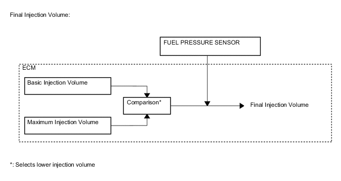
Fuel injection volume has 2 values, "Final Injection Volume", "Starting Injection Volume".
Final Injection Volume The ECM compares the basic and maximum injection volumes, and determines the smaller calculated value to be the final injection volume. The ECU reduces injection volume to ensure drivability when the clutch switch is on (the clutch pedal is depressed). Starting Injection Volume The starting injection volume is determined in accordance with the crank position sensor signal (cranking time) and diesel engine engine coolant temperature sensor signal. When the engine is cold, the engine coolant temperature will be lower and the injection volume will be greater. 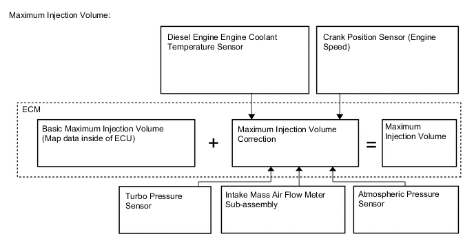
-
-
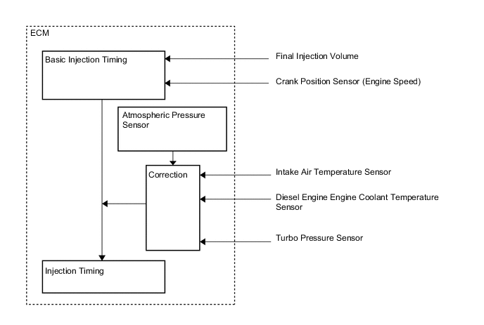
Fuel Injection Timing Control
-
Fuel injection timing is controlled as shown below.
-
-
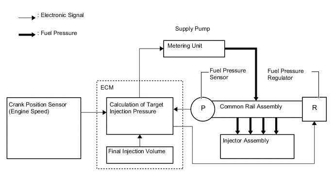
Fuel Pressure Control
-
The ECM calculates the target injection pressure (30 to 160 MPa) based on the final injection volume and signals from the crank position sensor.
-
To control fuel pressure, signals sent to metering unit of the supply pump regulate the pumping volume and signals sent to fuel pressure regulator of the common-rail regulate the discharge volume, so that the pressure detected by the fuel pressure sensor matches the target injection pressure.
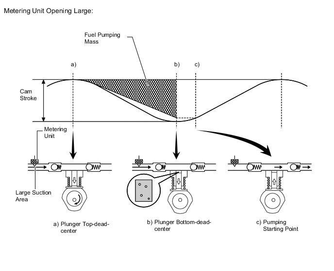
Metering unit Control The ECM controls the metering unit opening in order to regulate the fuel volume that is pumped by the supply pump to the common-rail. Consequently, the fuel pressure in the common-rail is controlled to the target injection pressure. Metering unit Opening Small When the metering unit opening is small, the fuel suction area is kept small, which decreases the transferable fuel quantity. The plunger strokes fully, however, the suction volume becomes small due to the small suction area. Pumping will start at the time when the fuel pressure has become higher than the common-rail pressure. Metering unit Opening Large When the metering unit opening is large, the fuel suction area is kept large, which increases the transferable fuel quantity. The plunger strokes fully, the suction volume will increase because the suction area is large. Pumping will start at the time when the fuel pressure has become higher than the common-rail pressure. 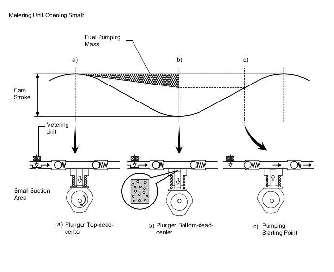
-
-
Idle Speed Control
-
ISC correction is controlled as shown below.
-
-
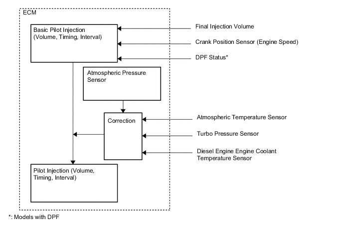
Pilot Injection Control
-
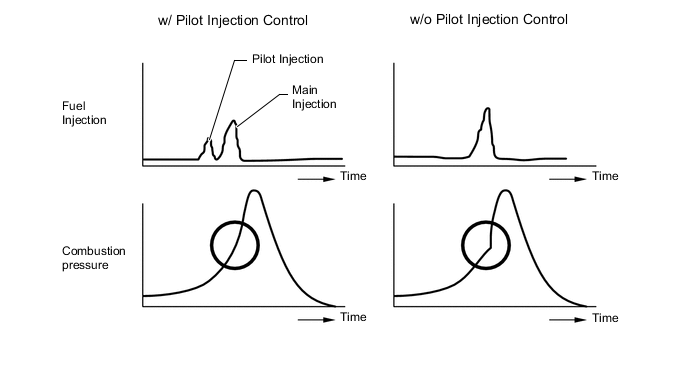
Pilot injection is a method that provides an auxiliary fuel injection before the main fuel injection takes place. The purpose of pilot injection is to gently start the combustion of the fuel of the main injection in order to reduce combustion noise.
-
During pilot injection, the pilot injection volume, timing, and interval (between pilot injection and main injection) are controlled as shown below.
-
-
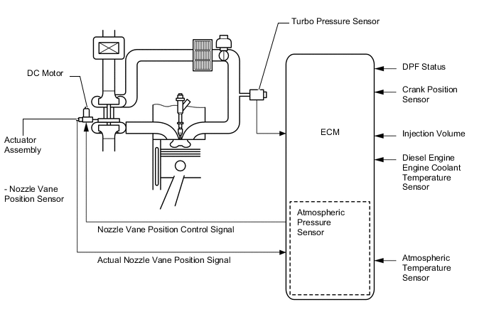
Turbocharger Control
-
The ECM controls the nozzle vane position, in order to obtain the calculated target turbo pressure appropriate to the engine operating condition.
-
The ECM calculates the optimal nozzle vane position in accordance with the driving conditions (engine speed, injection volume, atmospheric pressure and engine coolant temperature etc.). The ECM controls the nozzle vane position in accordance with the target nozzle vane position calculated by the ECM and the actual nozzle vane position signal provided by the nozzle vane position sensor.
-
-
-
CONSTRUCTION
-
Intake Mass Air Flow Meter Sub-assembly
-
The intake mass air flow meter sub-assembly of diesel engine uses precise fuel injection volume control and EGR control to realize clean emission.
-
This intake mass air flow meter sub-assembly, which is a slot-in type, allows a portion of the intake air to flow through the detection area. By directly measuring the mass and the flow rate of the intake air, the detection precision is improved and the intake air resistance is reduced.
-
The intake mass air flow meter sub-assembly has a built-in atmospheric temperature sensor.
-
In the intake mass air flow meter sub-assembly, the output voltage is converted into an output frequency by a frequency conversion circuit and is transmitted to the ECM. By converting the air flow meter output into frequency (frequency range between 250 to 11000 Hz), a more accurate intake air amount value can be gained because the value is then less likely to be affected by the differences between resistance of the individual circuits including the wire harnesses.
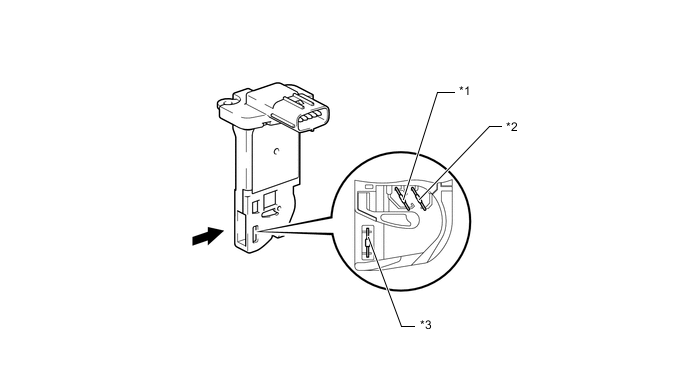
Text in Illustration *1 Hot Wire Element *2 Cold Wire Element *3 Atmospheric Temperature Sensor - - 
Air Flow - -
-
-
Crank Position Sensor
-
The crankshaft timing gear or sprocket of the crank position sensor consists of 58 teeth, with 2 teeth missing. The crank position sensor outputs the crankshaft rotation signals every 6° Crankshaft Angle (CA), and the missing teeth are used to determine the top-dead-center.
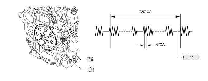
*a Crank Position Sensor *b 2 Teeth Missing *c Crankshaft Timing Gear or Sprocket
-
-
Cam Position Sensor
-
The pick-up coil type cam position sensor is used to detect the camshaft position. The sensor generates 1 signal in every 2 revolutions of the crankshaft by using the timing trigger (rib) of the camshaft.
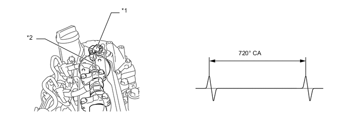
*1 Camshaft Position Sensor *2 Rib
-
-
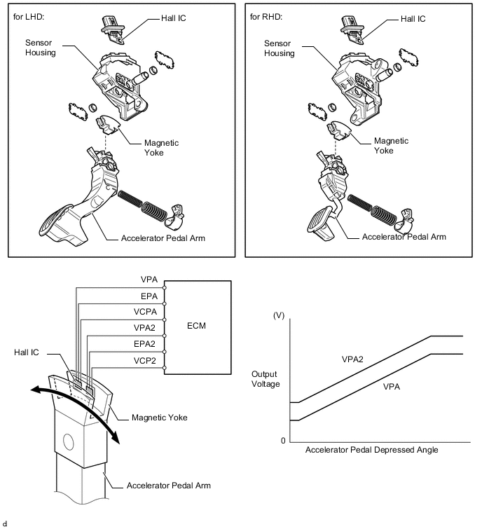
Accelerator Pedal Sensor Assembly
-
The non-contact type accelerator pedal sensor assembly uses a Hall IC.
-
The magnetic yoke mounted at the base of the accelerator pedal arm moves around the Hall IC in accordance with the amount of effort applied to the accelerator pedal. The Hall IC converts the changes in the magnetic flux that occur into electrical signals, and outputs them in the form of accelerator pedal effort to the ECM.
-
This accelerator pedal sensor assembly includes 2 Hall ICs and circuits for the main and sub signals. It converts the accelerator pedal depressed angles into electric signals with 2 differing characteristics and outputs them to the ECM.
-
-
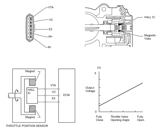
Throttle Position Sensor
-
The non-contact type throttle position sensor uses a Hall IC, which is integrated with the diesel throttle body assembly. A magnetic yoke surrounds the Hall IC. The Hall IC converts the changes that occur in the magnetic flux at that time into electrical signals and outputs them in the form of a diesel throttle control valve position to the ECM.
-
-
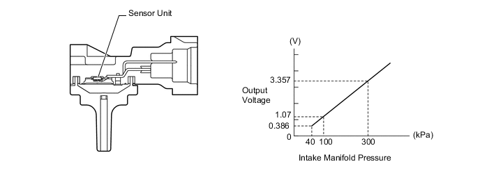
Turbo Pressure Sensor
-
The turbo pressure sensor consists of a semiconductor which utilizes the characteristic of a silicon chip that changes its electrical resistance when pressure is applied to it. The sensor converts the intake air pressure into an electrical signal, and sends it to the ECM in an amplified form.
-
-
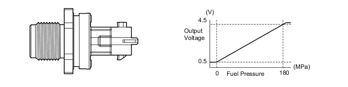
Fuel Pressure Sensor
-
The fuel pressure sensor consists of a semiconductor which utilizes the characteristic of a silicon chip that changes its electrical resistance when pressure is applied to it. This sensor is mounted on the common-rail, outputs a signal that represents the fuel pressure in the common-rail to the ECM, in order to constantly regulate the fuel at an optimal pressure.
-
-
Engine Oil Level Sensor
-
An engine oil level sensor, which detects the engine oil level and turns on or blinks the oil change reminder indicator light in the combination meter, is used.
-
For models with DPF, the engine oil level sensor has 2 switches; an oil upper level switch and oil lower level switch. The oil upper level switch, which is used in the post injection control, detects an increase in the engine oil level, and the other switch detects if the engine oil level has fallen below the predetermined level due to age.
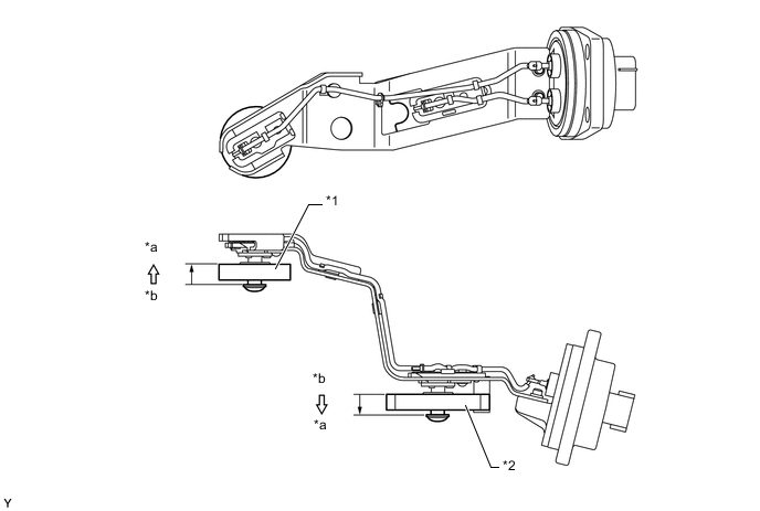
Text in Illustration (Models with DPF:) *1 Oil Upper Level Switch *2 Oil Lower Level Switch *a On *b Off 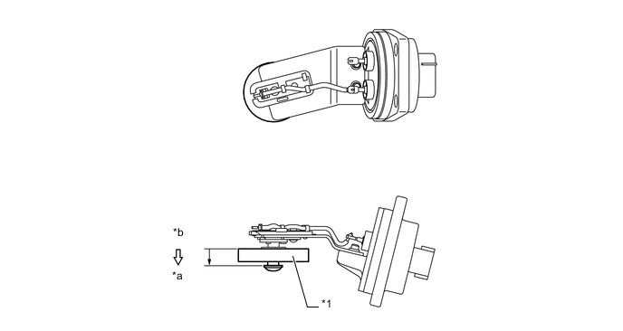
Text in Illustration (Models without DPF:) *1 Oil Upper Level Switch - - *a On *b Off
-
-
-
OPERATION
-
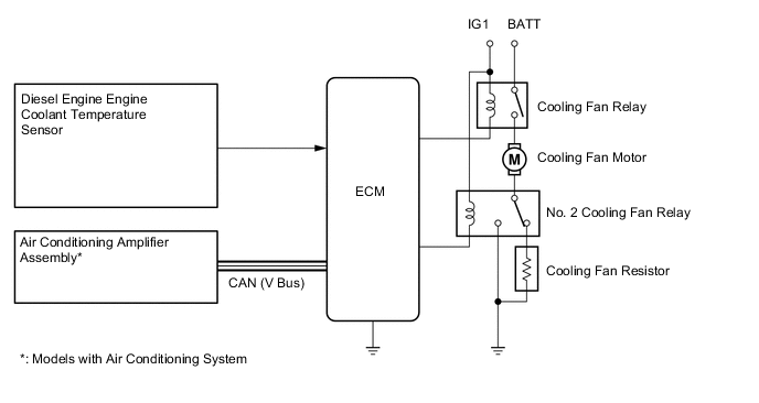
Cooling Fan Control System
-
According to the cooling fan drive request signal (low or high) from the air conditioning amplifier assembly and the engine coolant temperature, the ECM regulates the cooling fan speed over 2 levels. A cooling fan drive request signal is determined by the air conditioning amplifier assembly depending on mainly the refrigerant pressure and the A/C switch status.
-
The low speed operation is accomplished by applying the current through a resistor, which reduces the speed of the cooling fan.
Engine Coolant Temperature Cooling Fan Drive Request Signal Cooling Fan Operation Low Off Off Low Low High High High Off High Low High High High
-
-
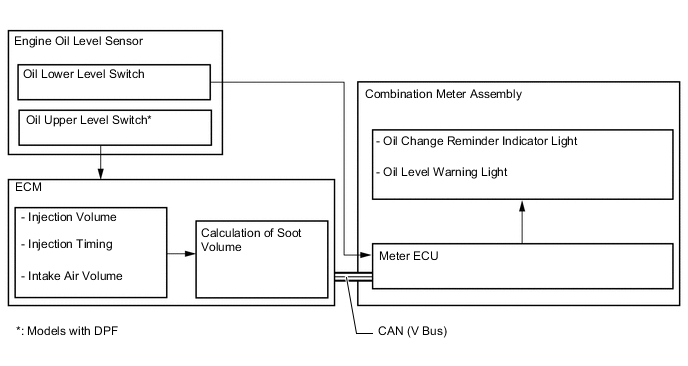
Oil Maintenance Management System
-
In the oil maintenance management system, the oil change reminder indicator light in the combination meter assembly blinks or turns on to inform the driver of when it is necessary to change the engine oil, when one of the following conditions is met: when the running distance exceeds a predetermined distance since the initial oil change or the last oil change, when the soot volume in the engine oil is calculated based on the engine operating conditions exceeds a predetermined volume, or when the oil level exceeds the level predetermined by the catalyst support control.
-
When controlling the oil change reminder indicator light based on the running distance, if the ECM detects that the running distance since the initial or last oil change is approximately 14500 km (9000 miles), the ECM blinks the indicator in the combination meter for 15 seconds after the ignition switch is turned to on, and then after another approximately 500 km (310 miles) of running distance without any oil change, the ECM constantly turns on the indicator.
-
In the control of the oil change reminder indicator light by the oil level sensor, when the sensor detects that the engine oil level exceeds a predetermined level, the ECM turns on or blinks the indicator. Whereas, when the sensor detects that the engine oil level has fallen below the predetermined level, the meter ECU turns on the oil level warning light.
Oil Upper Level Switch (Models with DPF) Oil Upper Level Switch Oil Change Reminder Indicator Light When the switch turns on Blinks When the running distance exceeds a predetermined distance since the switch was turned on Turns on Oil Lower Level Switch Oil Lower Level Switch Oil Level Warning Light When the switch turns on Turns on -
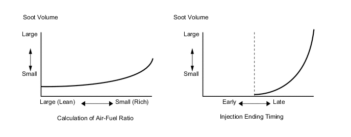
The ECM calculates soot volume from the injection volume, injection timing and intake air volume in order to operate this system.
-
The soot volume largely depends on injection ending timing and air-fuel ratio. The ECM calculates soot volume from this information as shown in the graphs below.
Tech Tips
When the engine oil is changed after the oil change reminder indicator light or the oil level warning light turns on or blinks, the ECM memory must be reset. For details, refer to the Repair Manual.
-
-
-
FAIL-SAFE
-
When the ECM detects a malfunction, the ECM stops or controls the engine according to the data already stored in the memory. For details, refer to the Repair Manual.
-
-
DIAGNOSIS
-
When the ECM detects a malfunction, the ECM diagnoses and memorizes the failed section. For details, refer to the Repair Manual.
-