FUEL SYSTEM
-
CONSTRUCTION
-
Supply Pump
-
The supply pump consists of an inner cam (eccentric cam), an outer cam (polygon ring), 3 plungers, a metering unit and a gear pump. Each plunger is placed outside of the outer cam.
-
Gear pump pumps fuel to 3 plungers.
-
Metering unit controls volume of fuel drawn into plungers.
-
Inner cam drives outer cam.
-
Outer cam drives 3 plungers.
-
Plunger pressurizes fuel.
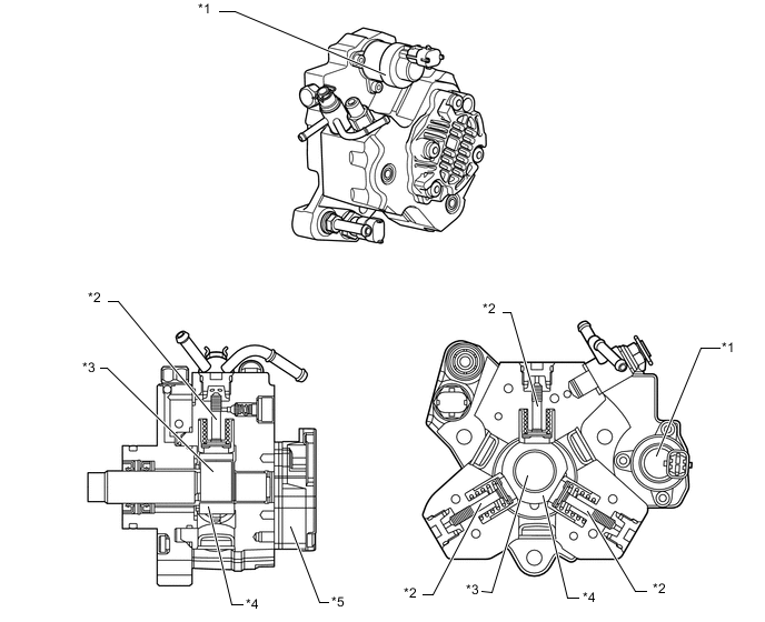
Text in Illustration (Models without DPF:) *1 Metering Unit *2 Plunger *3 Inner Cam *4 Outer Cam *5 Gear Pump - - 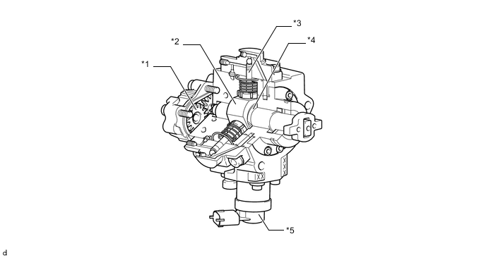
Text in Illustration (Models with DPF:) *1 Gear Pump *2 Outer Cam *3 Plunger *4 Inner Cam *5 Metering Unit - -
-
-
Common-rail
-
By storing fuel at a high pressure (30 to 160 MPa*1 / 30 to 180 MPa*2), the pump driving torque during the pumping of the fuel under high load condition has been restrained, thus reducing the vibration and noise of the fuel injection volume.
-
*1: Models without DPF
-
*2: Models with DPF
-
-
The fuel pressure sensor outputs the fuel pressure signal to the ECM.
-
The fuel pressure regulator is adjusting the fuel pressure in the common-rail in order to realize the optimum combustion and the reduction of combustion noise.
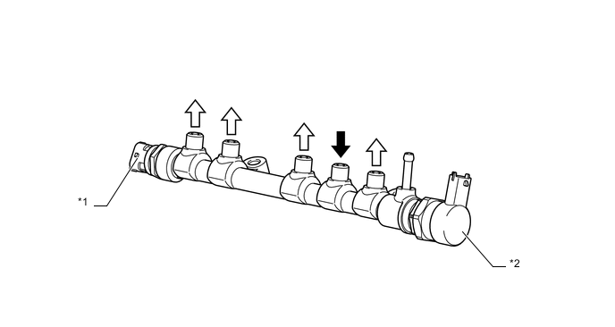
Text in Illustration (Models without DPF:) *1 Fuel Pressure Sensor *2 Fuel Pressure Regulator 
From Supply Pump 
To Injector 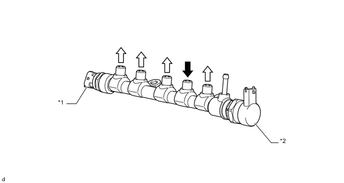
Text in Illustration (Models with DPF:) *1 Fuel Pressure Sensor *2 Fuel Pressure Regulator From Supply Pump To Injector
-
-
Injector Assembly (Models without DPF)
-
A 7-hole piezo type injector assembly is used to precisely control the fuel injection volume and timing.
-
This injector mainly consists of the piezo actuator, nozzle needle, valve bolt, amplifier piston and valve piston.
-
An injector compensation value and Data Matrix Code (DMC) containing encoded characteristics of the injector are printed on each injector assembly.
-
The injector compensation value and DMC contains various pieces of information regarding the injector assembly, such as model code, and injection volume correction.
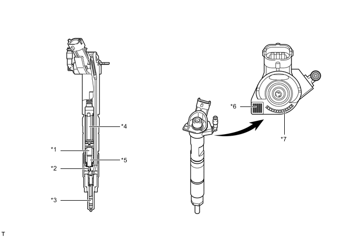
Text in Illustration *1 Amplifier Piston *2 Valve Bolt *3 Nozzle Needle *4 Piezo Actuator *5 Valve Piston *6 DMC *7 Injector Compensation Value - - Tech Tips
-
If an injector or the ECM is replaced, the injector compensation value can be entered in the ECM via the Global TechStream (GTS).
-
When an injector is replaced, enter the injector compensation value of the replaced injector only.
-
When the ECM is replaced, enter the injector compensation value of all injectors. The proper compensation will be made so that the injection volume precision prior to the replacement will remain unchanged.
-
The DMC, which requires a special scan tool, is not used at Toyota dealers.
-
-
-
Injector Assembly (Models with DPF)
-
An 8-hole solenoid valve type injector assembly is used.
-
Each injector assembly consists of a nozzle needle, a piston and a solenoid valve.
-
An injector compensation value (code) containing encoded characteristics of the injector is printed on each injector assembly.
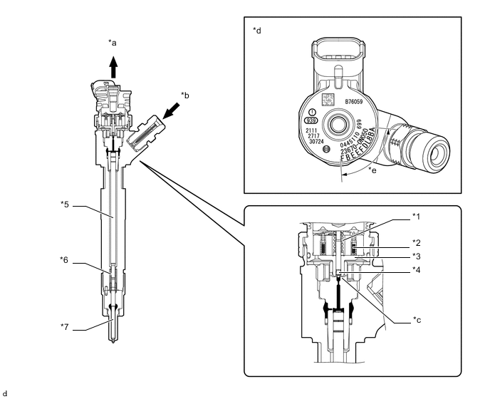
Text in Illustration *1 Solenoid Valve Spring *2 Solenoid Coil *3 Armature *4 Solenoid Valve *5 Piston *6 Nozzle Needle Spring *7 Nozzle Needle - - *a Fuel (Return) *b Fuel (from Common Rail Assembly) *c Orifice *d View from Top Side *e Compensation Value - - Tech Tips
-
Differences in the injection volume occur when the injector assembly is manufactured. The injection volume is measured after manufacturing. Based on the measured value, a compensation value (code) is assigned to each injector assembly. The compensation value (code) for each cylinder is stored in the ECM. The ECM corrects the injection volume based on the code.
-
When replacing an injector assembly, check that the code stored in the ECM and the code of the injector assembly match for each cylinder. For details of injector assembly replacement, refer to the Repair Manual.
-
-
-
Fuel Filter
-
A fuel filter assembly, in which the priming pump, fuel heater and fuel sedimenter level warning switch are integrated, is used.
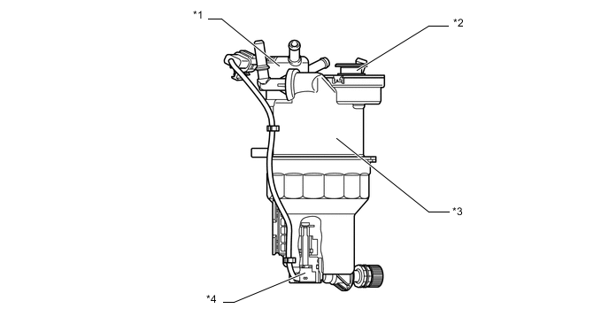
Text in Illustration *1 Preheating Valve *2 Priming Pump *3 Cover *4 Fuel Sedimenter Level Warning Switch
-
-
Fuel Heater
-
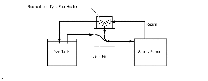
A recirculation type fuel heater is used. This heater heats the fuel by recirculating the returned fuel, which becomes to have a high temperature by the pumping of the supply pump, to the fuel filter.
-
-
Fuel Sedimenter Level Warning Switch
-
When the water in the sedimenter section reaches a certain amount, the fuel sedimenter level warning switch comes on, and the warning light in the combination meter assembly illuminates.
-
-
Fuel Tank Assembly
-
The multiplex layered plastic fuel tank is used. This fuel tank consists of 6 layers of 4 types of materials.
-
A drain mark has been provided at the lowest position of the fuel tank assembly. When dismantling (scrapping) the vehicle, drain fuel by drilling a hole at the drain mark.
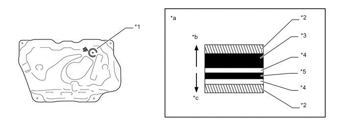
Text in Illustration *1 Fuel Drain Mark *2 High Density Polyethylene (HDPE) *3 Regrind Material *4 Adhesive *5 Ethylene Vinyl Alcohol Copolymer (EVOH) - - *a Fuel Tank Wall Cross Section *b Fuel Tank Assembly Outside *c Fuel Tank Assembly Inside - -
-
-
-
OPERATION
-
Supply Pump
-
Due to the rotation of the inner cam (eccentric cam), the outer cam pushes plunger "A" upward as illustrated below. The force of the spring pulls plunger "C". As a result, plunger "C" draws fuel in, and plunger "A" pumps fuel at the same time.
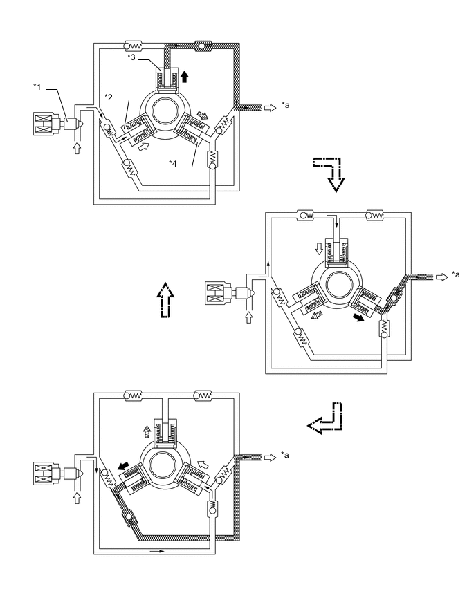
Text in Illustration *1 Metering Unit *2 Plunger C *3 Plunger A *4 Plunger B *a To Common Rail Assembly - - Pumping Finish Suction 
Pumping Start - -
-
-
Injector Assembly (Models without DPF)
-
The injector assembly operates as shown in the following table.
Needle Opening (During Injection)
-
The actuator is activated.
-
Valve bolt opens (moves downwards) due to actuator lift.
-
Pressure of nozzle needle tip decreases.
-
Nozzle needle opens (moves upwards).
Needle Closing (While Stopped)
-
The actuator is deactivated.
-
Valve bolt closes (moves upwards) due to the valve spring.
-
Pressure of nozzle needle tip increases.
-
Nozzle needle closes (moves downwards).
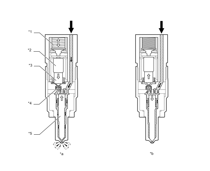
Text in Illustration *1 Piezo Actuator *2 Amplifier Piston *3 Valve Piston *4 Valve Bolt *5 Nozzle Needle - - *a During Injection *b While Stopped Fuel - - -
-
-
Injector Assembly (Models with DPF)
-
When electrical current is applied to the solenoid coil, it pulls the solenoid valve up.
-
The orifice of the control chamber opens, allowing the fuel to flow out.
-
The fuel pressure in the control chamber decreases.
-
Simultaneously, fuel flows from the orifice to the bottom of the piston and raises the piston up (to enhance response).
-
As a result, the piston raises the nozzle needle to inject fuel.
-
When the electrical current applied to the solenoid coil is stopped, the solenoid valve is pushed down and the orifice of the control chamber is closed.
-
The fuel pressure in the control chamber increases.
-
As a result, the piston and the nozzle needle are pushed down and fuel injection stops.
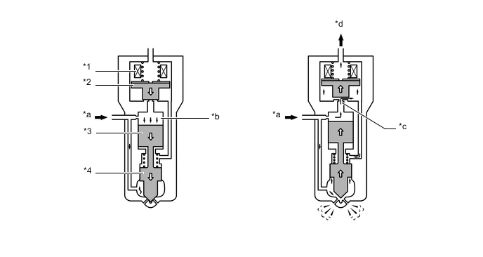
Text in Illustration *1 Solenoid Coil *2 Solenoid Valve *3 Piston *4 Nozzle Needle *a Fuel (from Common Rail Assembly) *b Control Chamber *c Orifice *d Fuel (Return)
-
-
Fuel Heater
-
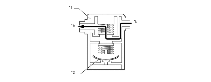
While the engine is cold, the recirculation valve inside the fuel heater will open due to the bimetal action, so the return fuel will return to the fuel filter and the fuel tank assembly.

Text in Illustration *1 Preheating Valve *2 Bimetallic Disc *a To Fuel Tank Assembly *b From Engine *c To Fuel Filter - - -
While the engine is warm, the recirculation valve will close due to the bimetal action, so all the return fuel will return to the fuel tank assembly.
Text in Illustration *1 Preheating Valve *2 Bimetallic Disc *a To Fuel Tank Assembly *b From Engine
-
-