BODY STRUCTURE
-
FUNCTION
-
Impact Absorbing Structure for Frontal Collision
-
A structure that ensures collision energy absorption efficiency, dissipates impact, and minimizes cabin deformation during a frontal collision has been achieved.
-
Impact energy from the front side member is dispersed to the rocker via the torque box, with the aim of suppressing cabin deformation.
-
Impact energy from the upper member is dispersed to the beltline reinforcement via the front body pillar bracket outer, with the aim of suppressing cabin deformation.
-
Impact energy from the upper member is dispersed to the roof rail via the front body pillar reinforcement lower inner, with the aim of suppressing cabin deformation.
-
By providing a front body pillar reinforcement upper outer with high sheet thickness in the front area of the front quarter window, excessive deformation of the front quarter window frame has been suppressed.
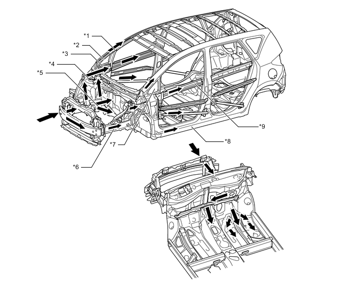
Text in Illustration *1 Front Body Pillar Reinforcement Lower Inner *2 Front Body Pillar Reinforcement Upper Outer *3 Front Body Pillar Bracket Outer *4 Upper Member *5 Torque Box *6 Front Side Member *7 Front Quarter Window *8 Rocker *9 Beltline Reinforcement - - 
Front Impact Energy - - -
-
-
Impact Absorbing Structure for Side Collision
-
A structure that ensures collision energy absorption efficiency, dissipates impact, and minimizes cabin deformation during a side collision has been achieved.
-
Mass increase has been suppressed by use of ultra high-tensile strength steel on the rocker outer reinforcement and the center pillar hinge upper reinforcement, and high-tensile strength steel on the rail outer reinforcement, the center pillar lower hinge reinforcement and others. At the same time, a prevention of cabin deformation by ensuring the proof strength of the vehicle against side impact energy has been aimed for.
-
By giving the sides of the roof panel reinforcement a closed cross section, and thus ensuring a high level of proof strength against side impact energy, cabin deformation suppression has been aimed for.
-
By providing bulkheads inside the rockers and thus controlling rocker bending, cabin deformation suppression has been aimed for.
-
By optimally locating the door side impact protection beam, and thus providing a structure that effectively transmits load, cabin deformation suppression has been aimed for.
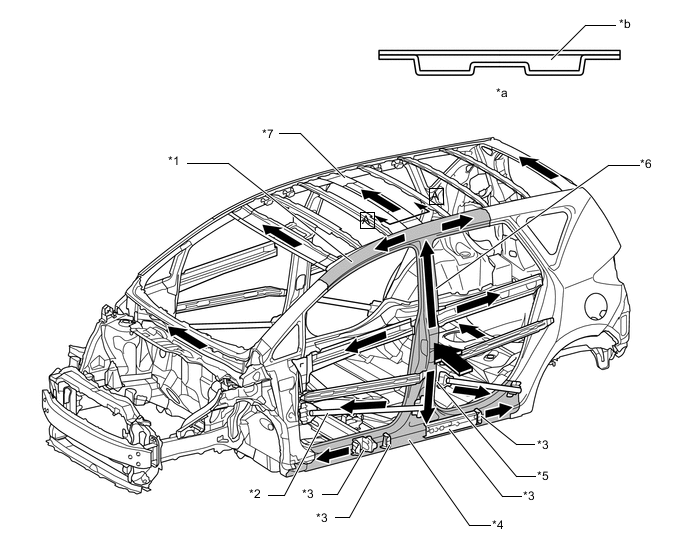
Text in Illustration *1 Rail Outer Reinforcement *2 Door Side Impact Protection Beam *3 Bulkhead *4 Rocker Outer Reinforcement *5 Center Pillar Lower Hinge Reinforcement *6 Center Pillar Upper Hinge Reinforcement *7 Roof Panel Reinforcement - - *a A - A Cross Section *b Closed Cross Section Side Impact Energy - - -
-
Door trim pads are provided in the door trims to help dampen the impact applied from the sides of the vehicle to the occupants.
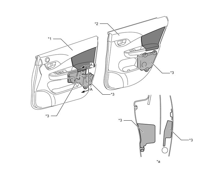
Text in Illustration *1 Front Door Trim *2 Rear Door Trim *3 Door Trim Pad - - *a A - A Cross Section - -
-
-
Head Impact Protection Structure
-
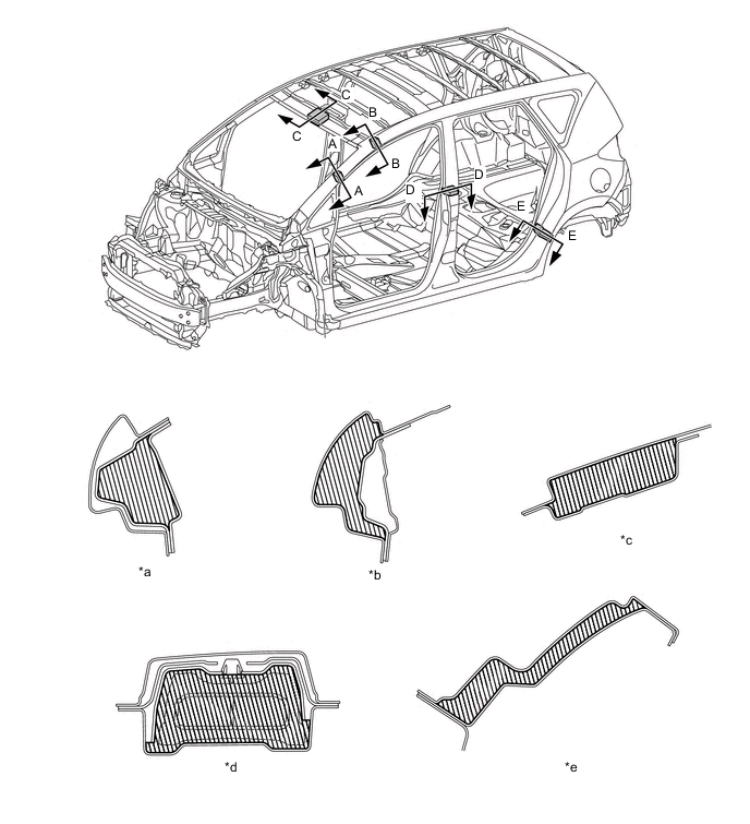
An energy absorber is provided in the roof and pillars, thus taking into consideration the reduction of impact energy to the heads of passengers in the event of an impact in which the heads of passengers receive strong impact energy.
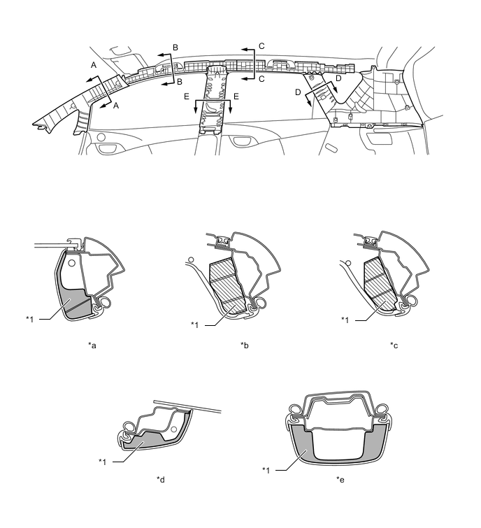
Text in Illustration *1 Energy Absorber - - *a A - A Cross Section *b B - B Cross Section *c C - C Cross Section *d D - D Cross Section *e E - E Cross Section - -
-
-
Lessening Pedestrian Head Injury
-
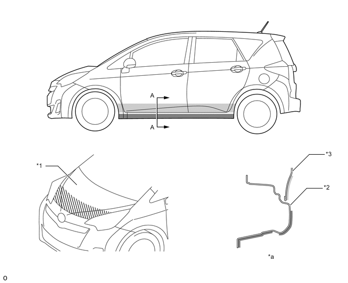
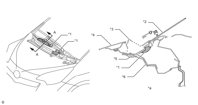
Fold lines are provided on the hood panel inner to encourage deformation in the event of a collision with a pedestrian. Also, a pantagraph construction, which absorbs the impact it receives while collapsing, is used in the hood lock hook sub-assembly. During a collision with a pedestrian, a space for the pedestrian's head to stroke is ensured, with the aim of reducing the predicted impact to the pedestrian's head.
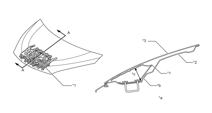
Text in Illustration *1 Hood Lock Hook Sub-assembly *2 Hood Panel Inner *3 Hood Panel - - *a A - A Cross Section *b Fold Line *c Stroke Space - - -
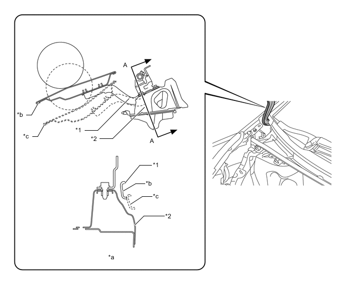
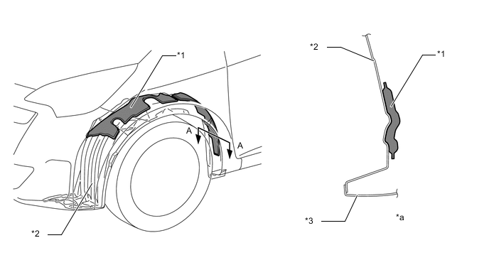
Fender brackets is used in the joint portion of the front fender. Fold points and holes are provided on the fender brackets. Therefore, during a collision with a pedestrian, the fender brackets absorb impact energy, with the aim of reducing the predicted impact to the pedestrian's head.
Text in Illustration *1 Fender Bracket - - *a Hole *b Fold Point -
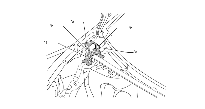
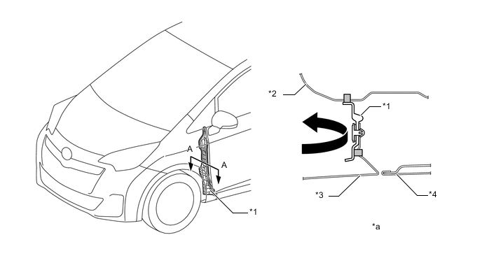
The hood hinge arm and the hood hinge mounting reinforcement have been made to pass each other without making contact when a pedestrian is collided with and the hood hinge parts receive impact force from the pedestrian, with the aim of lessening the impact force inflicted upon the pedestrian.
Text in Illustration *1 Hood Hinge Arm *2 Hood Hinge Mounting Reinforcement *a A - A Cross Section *b Before Collision *c After Collision - -
-
-
Lessening Pedestrian Leg Injury
-
A front bumper energy absorber and a front bumper absorber lower are provided in front of the front bumper reinforcement and below the radiator support lower. This structure helps lessen the impact applied to the legs of the pedestrians.
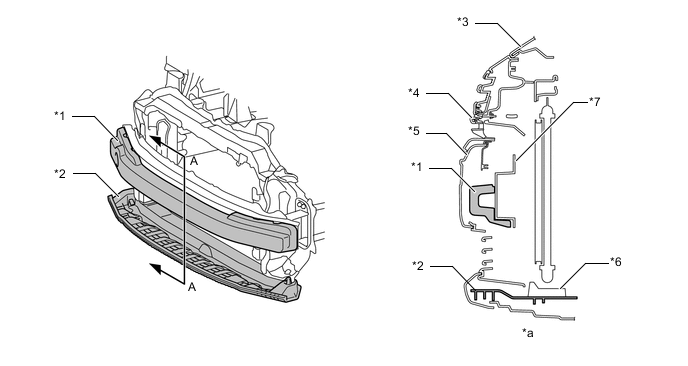
Text in Illustration *1 Front Bumper Energy Absorber *2 Front Bumper Absorber Lower *3 Hood Panel *4 Radiator Grille *5 Front Bumper Cover *6 Radiator Support *7 Front Bumper Reinforcement - - *a A - A Cross Section - -
-
-
Aerodynamics
-
A rear spoiler is provided, giving a rectifying effect and allowing superior aerodynamic performance.
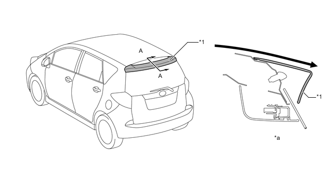
Text in Illustration *1 Rear Spoiler - - *a A - A Cross Section - - Air Flow - - -
A front spoiler cover is provided underneath the front bumper cover. The front spoiler cover uses an L-shaped cross section rather than the conventional straight cross section. Compared to the straight cross section, the L-shaped cross section can suppress the flow of air to the underside of the vehicle, thus reducing air resistance and contributing to an improvement in fuel economy.
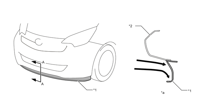
Text in Illustration *1 Front Spoiler Cover *2 Front Bumper Cover *a A - A Cross Section - - Air Flow - - -
Front and rear air spats are provided, thus enhancing aerodynamic characteristics by adjusting the airflow to the tires and the wheel house section.
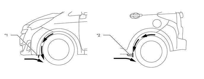
Text in Illustration *1 Front Air Spat *2 Rear Air Spat Air Flow - -
-
-
-
CONSTRUCTION
-
Lightweight Body
-
High-tensile strength steel
-
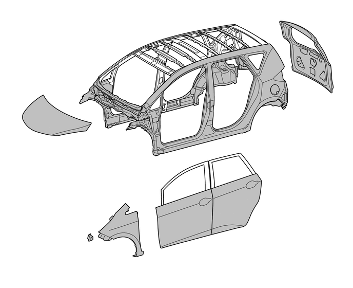
High-tensile strength steel and ultra high-tensile strength steel are used in order to achieve excellent body rigidity and a lightweight body.
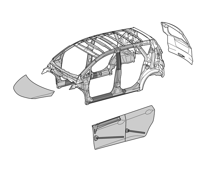
Text in Illustration (Upper Body) 
High-tensile Strength Steel 
Ultra High-tensile Strength Steel 
Text in Illustration (Under Body) High-tensile Strength Steel Ultra High-tensile Strength Steel -
-
-
Stability and Controllability
-
Highly Rigid Body
-
Sufficient rigidity has been ensured by using the cowl top panel outer as a framework cross member to smoothly connect the left and right front suspension towers. In this way, good driving stability has been achieved.
-
By providing a cowl top inside corner panel on top of the front spring support, and by increasing the number of joints between the cowl top panel outer and the body, the coupling rigidity of the left and right front suspension towers has been increased, and increases in driving stability (for example in handling response) have been aimed for.
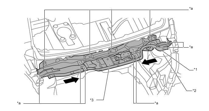
Text in Illustration *1 Cowl Top Inside Corner Panel *2 Front Spring Support *3 Cowl Top Panel Outer - - *a Joint - - Force Transmission - - -
-
-
Anti-corrosion Sheet Steel
-
Anti-corrosion sheet steel is used as in the following illustration:
Text in Illustration (Upper Body) Anti-corrosion Sheet Steel - - 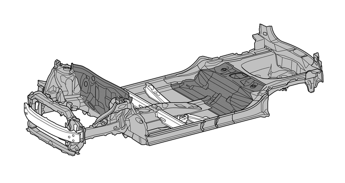
Text in Illustration (Under Body) Anti-corrosion Sheet Steel Anti-corrosion Sheet Steel (Europe Only)
-
-
Anti-chipping Application and Rust-resistant Performance
-
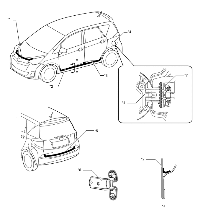
Polyvinyl Chloride (PVC), urethane and soft chipping primer are applied to various parts of the body to help prevent rust.
Text in Illustration *1 Hood Panel *2 Side Panel Outer *3 Front Door Panel Outer - - *a A - A Cross Section - - PVC Urethane 
Soft Chipping Primer - - -
Hinge wax is applied to the fuel filler lid hinge and door hinge, and cavity wax is applied to the hemmed portions of the hood panel, edge of the door lower portion and edge of the luggage compartment door lower portion to improve rust-resistant performance.
Text in Illustration *1 Hood Panel *2 Front Door Panel Outer *3 Rear Door Panel Outer *4 Fuel Filler Lid *5 Back Door Panel *6 Door Hinge *7 Fuel Filler Lid Hinge - - *a A - A Cross Section - - 
Cavity Wax Hinge Wax -
Under coating is applied to the under side of the body, inside the wheel housing and other parts that are susceptible to stone chipping damage, thus improving the rust-resistant performance of these areas.
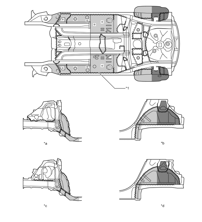
Text in Illustration *1 Edge Seal - - *a Front Wheel House RH *b Rear Wheel House RH *c Front Wheel House LH *d Rear Wheel House LH Under Coating Area (1.0 mm or more) Under Coating Area (2.0 mm or more)
-
-
Sound Absorbing and Vibration Damping Materials
-
A hood insulator is provided on the rear of the hood panel. This achieves excellent sound insulation performance.
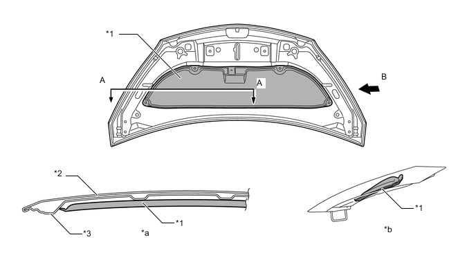
Text in Illustration *1 Hood Insulator *2 Hood Panel *3 Hood Panel Inner - - *a A - A Cross Section *b View from B -
A dash panel insulator outer is provided. This reduces the amount of engine noise leaking into and out of the cabin.
-
In accordance with model type, an engine under cover silencer is provided. This reduces the amount of engine noise leaking into and out of the cabin.
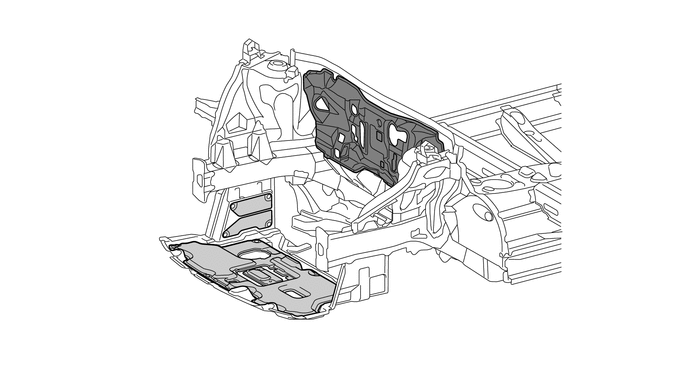
Text in Illustration Dash Panel Insulator Outer Engine Under Cover Silencer -
A dash panel insulator is provided. This insulates and absorbs the engine noise to reduce the amount of engine noise leaking into the cabin.
-
In accordance with model type, a front floor silencer (asphalt sheet) is used, thus suppressing floor panel vibrations. Also, a tunnel silencer is used in the tunnel area, thus insulating against noise coming from the tunnel area. As a result, a high level of quietness is ensured.
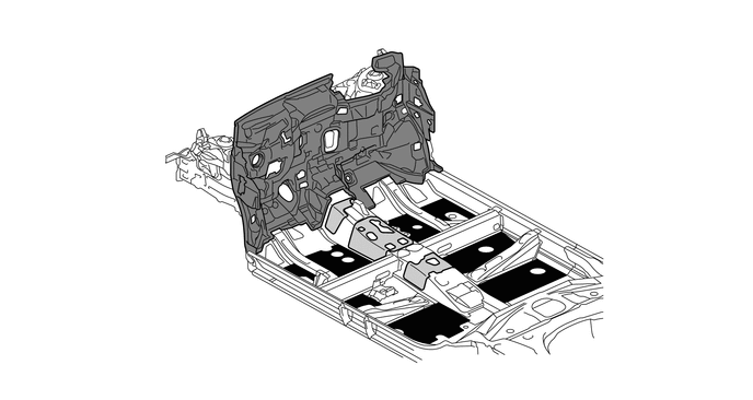
Text in Illustration Dash Panel Insulator Front Floor Silencer Tunnel Silencer - - -
All the locations of sound insulation and absorption materials in the cabin have been optimized, thus creating a quiet drive.
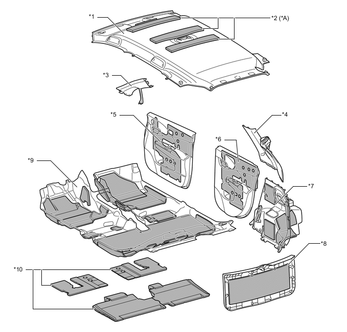
Text in Illustration *A Models with Normal Roof - - *1 Roof Headlining (Acoustic Ceiling) *2 Roof Silencer Pad (Acoustic Felt) *3 Front Pillar Garnish (Acoustic Felt) *4 Roof Side Garnish (Acoustic Felt) *5 Front Door Trim Board (Acoustic Felt) *6 Rear Door Trim Board (Acoustic Felt) *7 Deck Trim Side Panel (Acoustic Felt) *8 Back Door Trim Board (Acoustic Felt) *9 Floor Carpet (Acoustic Felt) *10 Floor Silencer (Acoustic Type) -
In accordance with model type, a dash panel insulator outer No. 2 is provided underneath the cowl top panel outer. By doing so, noise coming from the engine compartment has been reduced.
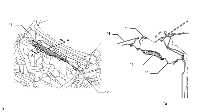
Text in Illustration *1 Dash Panel Insulator Outer No. 2 *2 Cowl Top Panel Outer *3 Cowl Top Ventilator Louver *4 Hood Panel *a A - A Cross Section - - -
In accordance with model type, an insulator is used on the underside of the cowl top ventilator louver to reduce sound permeating into the cabin from the engine compartment.
Text in Illustration *1 Insulator *2 Windshield Glass *3 Cowl Top Ventilator Louver *4 Hood Panel *5 Cowl Vent Splash Shield *6 Cowl Top Panel Outer *a A - A Cross Section - - -
In accordance with model type, a fender liner silencer is used on the underside of the fender liner to reduce road noise permeating into the cabin from the tires.
Text in Illustration *1 Fender Liner Silencer *2 Fender Liner *3 Fender Panel - - *a A - A Cross Section - - -
A front fender side panel protector is provided between the cowl top side panel and the front fender panel. This prevents road noise from entering the cabin, and achieves superior quietness.
Text in Illustration *1 Front Fender Side Panel Protector *2 Side Panel Outer *3 Fender Panel *4 Front Door Panel Outer *a A - A Cross Section - - Noise - - -
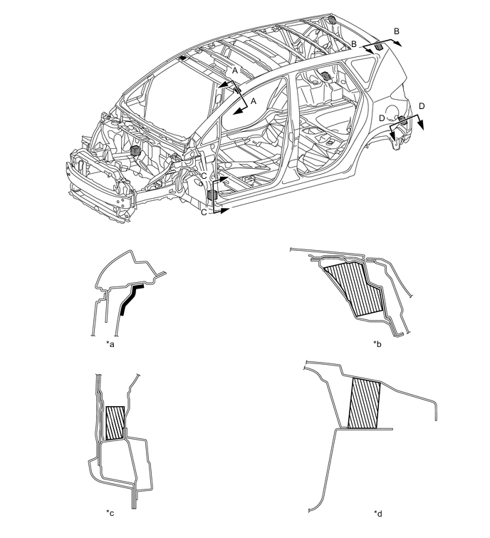
A foam type sound insulation material is used in the body frame profile, thus dampening the various noises which intrude from the outside of the vehicle to the inside of the cabin.
Text in Illustration *a A - A Cross Section *b B - B Cross Section *c C - C Cross Section *d D - D Cross Section *e E - E Cross Section - - Foam Type Sound Insulation Material - - -
By providing rubber asphalt sheet (or polyethylene sheet) and slab polyurethane foam on the machinable holes and the body frame profile, and thus blocking paths through which sound can enter, road noise permeating into the cabin has been reduced.
Text in Illustration *a A - A Cross Section *b B - B Cross Section *c C - C Cross Section *d D - D Cross Section Rubber Asphalt Sheet (or Polyethylene Sheet) Slab Polyurethane Foam -
On models with normal roof, by optimizing the numbers and the locations of the roof panel reinforcement, and thus suppressing roof panel shudder, muffled sounds at low to medium speeds have been reduced. The central portions of the front two pieces of roof panel reinforcement have been widened, and roof shudder is suppressed by the mass effect of the central portions, thus reducing muffled sounds at low to medium speeds (the unit by itself achieves effectiveness equivalent to the effectiveness that would be achieved by adding dynamic dampers to the central portions).
-
A dynamic damper (windshield header panel damper) is used on the windshield header panel on models with panoramic roof, with the aim of reducing muffled sounds coming from the road.
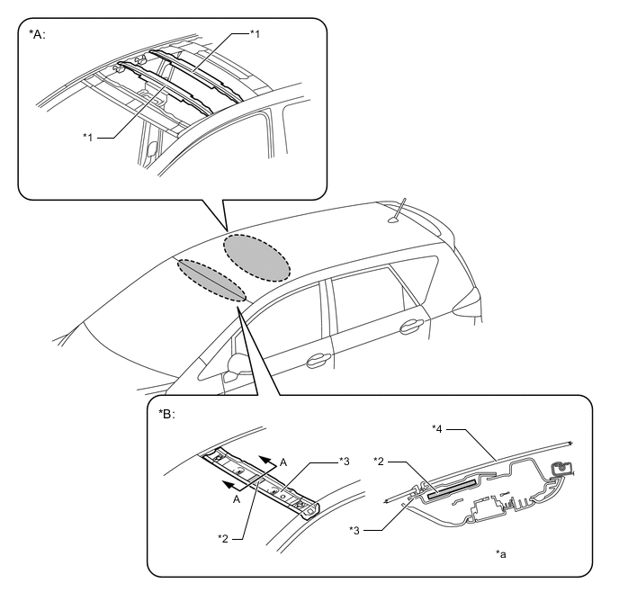
Text in Illustration *A Models with Normal Roof *B Models with Panoramic Roof *1 Roof Panel Reinforcement *2 Windshield Header Panel Damper *3 Windshield Header Panel Sub-assembly *4 Roof Window Glass Sub-assembly *a A - A Cross Section - - -
By providing a dynamic damper (back door damper assembly) on the back door, and thus suppressing back door shudder, muffled sounds inside the vehicle have been reduced.
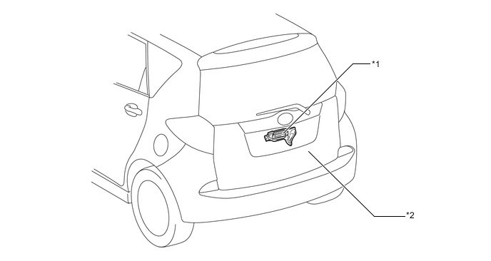
Text in Illustration *1 Back Door Damper Assembly *2 Back Door -
Rocker panel molding is provided on the underside of the rockers, thus reducing the sound of sand and pebbles thrown up from the road.
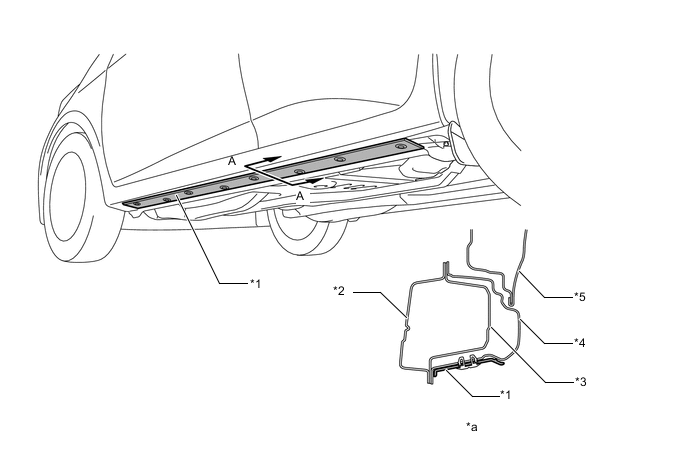
Text in Illustration *1 Rocker Panel Molding *2 Floor Side Member Inner *3 Rocker Reinforcement Outer *4 Side panel Outer *5 Door Panel - - *a A - A Cross Section - - -
An acoustic layer laminated windshield glass is provided to reduce the engine noise and road noise intruding into the cabin.
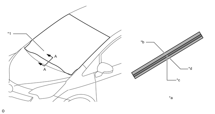
Text in Illustration *1 Windshield Glass - - *a A - A Cross Section *b Outside Glass *c Acoustic Layer *d Interior Side Glass
-
-
Parts with Low Repair Cost
-
A crush box structure is used to reduce body deformation during minor collisions. A structure with screw connections is provided for crush box to enable easy removal and installation, thus achieving simpler servicing operation and repair cost reduction.
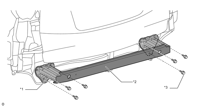
Text in Illustration *1 Crush Box (Rear Bumper Arm Sub-assembly) *2 Rear Bumper Reinforcement *3 Bolt - -
-
-