LIGHTING SYSTEM
-
FUNCTION OF MAIN COMPONENTS
-
Daytime Running Light System
Component Function Main Body ECU (Multiplex Network Body ECU) The main body ECU (multiplex network body ECU) receives various signals and illuminates the daytime running lights. Daytime Running Light Relay Supplies power to the daytime running lights. Headlight Dimmer Switch Assembly Light Control Switch The light control switch outputs a light control signal and transmits it to the main body ECU (multiplex network body ECU). ECM The ECM outputs an engine speed signal and transmits it to the main body ECU (multiplex network body ECU). Parking Brake Switch Assembly The parking brake switch assembly outputs a parking brake operation signal to the main body ECU (multiplex network body ECU). -
Automatic Light Control System
Component Function Main Body ECU (Multiplex Network Body ECU) The main body ECU (multiplex network body ECU) receives various signals and illuminates the headlights, taillights, clearance lights, and license plate lights. Headlight Dimmer Switch Assembly Light Control Switch The light control switch transmits an AUTO position signal to the main body ECU (multiplex network body ECU). Automatic Light Control Sensor The automatic light control sensor detects the ambient light level. -
HID Headlight System
Component Function Main Body ECU (Multiplex Network Body ECU) The main body ECU (multiplex network body ECU) receives the HEAD position signal and transmits a signal to the light control ECU. Headlight Dimmer Switch Assembly Light Control Switch The light control switch transmits a HEAD position signal to the main body ECU (multiplex network body ECU). Headlight Unit Headlight Light Control ECU Sub-assembly The headlight light control ECU sub-assembly transforms battery voltage to a high voltage of up to 30000 V and applies it to the discharge bulbs in order to illuminate them. Discharge Bulb The discharge bulb light shines ahead over a broader area and further forward, increasing the area visible to the driver. -
Automatic Headlight Beam Level Control System
Component Function Headlight Leveling ECU Assembly The headlight leveling ECU assembly receives various signals, calculates the target lighting angle, and actuates the headlight leveling motor. Headlight Leveling Motor
-
Based on the signals received from the headlight leveling ECU assembly, the motors move the reflectors in the headlights.
-
Uses a step motor to precisely regulate the angle of the reflectors.
Rear Height Control Sensor Sub-assembly RH Detects the height of the vehicle. Main Body ECU (Multiplex Network Body ECU) Transmits the headlight status signal. Combination Meter Assembly
-
If the system malfunctions, the meter ECU alerts the driver by illuminates the automatic headlight beam level control system warning light in accordance with the signal from the headlight leveling ECU assembly.
-
Transmits the vehicle speed signal to headlight leveling ECU assembly.
-
-
Manual Headlight Beam Level Control System
Component Function Headlight Leveling Switch The level of the headlight can be adjusted between 0 and 5, and a switch level status signal is sent to the actuator. Headlight Leveling Motor Headlight Leveling Motors in accordance with signals from the headlight leveling switch and moves the reflector up and down. -
Emergency Brake Signal
Component Function Brake Actuator Assembly
- Skid Control ECU
Receives various signals and transmits an emergency brake signal to the combination meter assembly. Speed Sensor Detect the wheel speed of each of the 4 wheels. Airbag Sensor Assembly Outputs the acceleration information. Stop Light Switch Assembly Detects the brake pedal depressing signal. Combination Meter Assembly The hazard warning light is made to blink in accordance with the operation signal of the emergency brake signal from the skid control ECU.
-
-
OPERATING CONDITION
-
Daytime Running Light System
-
The daytime running light system is enabled when the conditions given below are met:
Condition Ignition switch (engine switch*) is ON. An engine speed signal is input (engine running). Light control switch OFF or AUTO position (when taillight is not being controlled by the automatic light control). Parking brake is off. Tech Tips
*: Models with entry and start system
-
-
Follow Me Home System
-
The follow me home system is enabled when the conditions given below are met:
Condition Ignition switch (engine switch*) is OFF. Light control switch OFF or AUTO position. Dimmer switch is pulled to flash headlights once. Tech Tips
*: Models with entry and start system
-
-
Emergency Brake Signal
-
The activating and deactivating conditions for the emergency brake signal are as shown in the following table:
Condition Details Emergency Brake Signal Operating Conditions When all of the following conditions are met, the emergency brake signal starts operating:
-
Vehicle speed is above 55 km/h (35 mph).
-
Driver is depressing the brake pedal.
-
Emergency braking is detected from the vehicle deceleration.
Emergency Brake Signal Ending Conditions When any of the following conditions is met, the emergency brake signal stops operating:
-
Driver has released the brake pedal.
-
Emergency braking is no longer detected from the vehicle deceleration.
-
Driver has pressed the hazard warning signal switch.
-
-
-
-
FUNCTION
-
Daytime Running Light System
-
The daytime running light system is controlled by the main body ECU (multiplex network body ECU). The main body ECU (multiplex network body ECU) illuminates the daytime running light (LED).
-
-
Automatic Light Control System
-
When the light control switch is in the AUTO position, the automatic light control sensor detects the ambient light level and automatically turns the headlights, taillights, clearance lights, and license plate lights on or off accordingly.
-
This system is controlled by the main body ECU (multiplex network body ECU).
-
-
Follow Me Home System
-
The follow me home system is controlled by the main body ECU (multiplex network body ECU). The main body ECU (multiplex network body ECU) illuminates the low beam.
-
-
Light Automatic Turn-off System
-
The light automatic turn-off system is controlled by the main body ECU (multiplex network body ECU).
-
This system has the following functions:
Destination Switch Position Outline TAIL HEAD AUTO Europe - - ○ While the lights (headlight, front fog light*1, rear fog light, and taillight) are turned on, this system automatically turns them off when the ignition switch (engine switch*2) is turned off. ○ ○ - While the lights (headlights, front fog lights*1, rear fog light, and taillights) are turned on, this system automatically turns off only the headlights and the front fog lights*1 when the ignition switch (engine switch*2) is turned off. Hong Kong ○ ○ ○ While the lights (headlight, front fog light*1, and taillight) are turned on, this system automatically turns them off when the ignition switch (engine switch*2) is turned off and the driver's door is opened. -
After the lamp auto cut system was activated, when the ignition switch (engine switch*2) is shifted from on to off while the light control switch (HEAD) is turned on or is in the AUTO position, the battery saving function turns off the headlights and taillights automatically in approximately 20 minutes. In addition, when one of the doors is opened from the closed status or closed from the opened status, the accumulated time is reset and the lights turn off in approximately 20 minutes after the door was opened/closed.
Tech Tips
*1: Models with front fog light
*2: Models with entry and start system
-
-
HID Headlight System
-
The HID headlight system consists of discharge bulbs and headlight light control ECU sub-assembly.
-
Headlight light control ECU sub-assembly transforms the voltage that is input from the battery to a high voltage of up to 30000 V and applies it to the discharge bulbs in order to illuminate them.
-
A fail-safe function is provided as a countermeasure against the high voltage generated when a problem occurs in the headlight system.
-
-
Automatic Headlight Beam Level Control System
-
The automatic headlight beam level control system mainly consists of the headlight leveling ECU assembly, rear height control sensor RH sub-assembly, and two headlight leveling motors.
-
The headlight leveling ECU assembly calculates changes in the vehicle posture based on the signals from the rear height control sensor RH sub-assembly.
-
Following this, the ECU controls the headlight leveling motor based on this information, in order to change the headlight reflector angle.
-
Initial Set Control
When the engine is started, the headlight leveling ECU assembly drives the headlight leveling motor, moves the headlight reflector to the lower limit position and returns it to the proper position. The headlight leveling ECU assembly thus assesses the position of the headlight for reference control.
-
-
Light Reminder System
-
The light reminder system warns the driver using a buzzer when the meter ECU inside the combination meter assembly receives the driver's door courtesy light switch signal via the main body ECU (multiplex network body ECU) and the ignition switch is turned off and the door is opened with the taillights kept on. The buzzer is located inside the combination meter.
Light control switch position Ignition switch*1 or Engine Switch*2 Door Buzzer Tail, Head Switch off Open Sounds Closed - Tech Tips
*1: Models without Entry and Start System
*2: Models with Entry and Start System
-
-
Emergency Brake Signal
-
This function automatically flashes the hazard warning lights in 4 Hz cycles during sudden braking, in order to alert vehicles behind and reduce the risk of an accident.
-
-
-
CONSTRUCTION
-
Bi-function
-
When the low beam is selected, the lower illumination area of the bulb is blocked by a shade and only the upper illumination area is used.
-
When the high beam is selected, the headlight actuator slides the shade down to allow use of the lower illumination area, thus increasing the illumination area and improving visibility when the high beam is selected.
-
The bi-function is activated by the main body ECU (multiplex network body ECU). The main body ECU (multiplex network body ECU) receives as signal to turn on the high beams from the headlight dimmer switch assembly, then activates the built-in headlight actuator to slide the shade down.
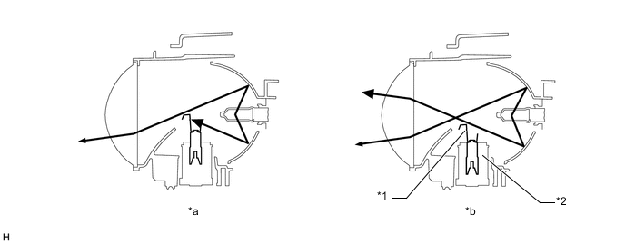
Text in Illustration *1 Shade *2 Headlight Actuator *a Low Beam *b High Beam
-
-
HID Headlight System
-
Discharge Bulb
Instead of the filament contained in an incandescent bulb, a discharge bulb contains an arc tube, which is filled with xenon gas, and metal halide.
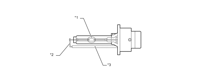
Text in Illustration *1 Arc Tube *2 Lead Wire *3 Ceramic Pipe - - -
Discharge bulbs have the following advantages:
-
The light emitted by the bulb is close in color to sunlight. The light shines ahead over a broader area and further forward, increasing the area visible to the driver.
-
Less power is consumed.
-
-
-
-
FAIL-SAFE
-
HID Headlight System
-
The light control ECU executes the fail-safe actions listed below in accordance with the problem that has been detected:
Condition Content Open in output side circuit
-
Stops illuminating the headlights.
-
Keeps the headlights off until the power is reinstated (by turning the light control switch from off to the head position).
Short between output terminals
-
Stops illuminating the headlights.
-
Keeps the headlights off until the power is reinstated (by turning the light control switch from off to the head position).
Leak between output terminal and body ground
-
Stops illuminating the headlights.
-
Keeps the headlights off until the power is reinstated (by turning the light control switch from off to the head position).
Excessively low output voltage
-
Stops illuminating the headlights when the output voltage becomes too low (31 +/- 3 V or less).
-
Keeps the headlights off until the power is reinstated (by turning the light control switch from off to the head position).
Excessively high output voltage
-
Stops illuminating the headlights when the output voltage becomes too high (69 +/- 4 V or more).
-
Keeps the headlights off until the power is reinstated (by turning the light control switch from off to the head position).
Excessively high input voltage
-
Stops illuminating the headlights when the input voltage becomes too high (17 V or more).
-
Illuminates the headlights again when the voltage returns to the operating voltage range (10 to 16 V).
Low input voltage
-
Stops illuminating the headlights when the input voltage becomes too low (below 6 V).
-
Illuminates the headlights again when the voltage returns to the operating voltage range (10 to 16 V).
-
-
-
Automatic Headlight Beam Level Control System
-
If the headlight leveling ECU assembly detects a malfunction in the automatic headlight beam level control system, it will take the actions indicated in the table below:
Trouble Area Fail-safe Control Automatic Headlight Beam Level Control System Warning Light Abnormal power source voltage:
-
High voltage (18.5 V or more)
-
Low voltage (9.0 V or less)
Control signal output to the headlight leveling motor LH/RH is stopped. Not illuminates Abnormal rear height control sensor sub-assembly RH power source voltage:
-
High Voltage (6.25 V or more)
-
Low Voltage (4.6 V or less)
Illuminates Abnormal rear height control sensor sub-assembly RH signal voltage:
-
High Voltage (4.75 V or more)
-
Low Voltage (0.25 V or less)
Inappropriate voltage at initialization:
-
The rear height control sensor sub-assembly RH voltage was inappropriate at initialization.
Invalid vehicle codes:
-
The headlight leveling ECU assembly dose not support the written vehicle codes or is not able to read them.
-
-
-
-
DIAGNOSIS
-
Automatic Headlight Beam Level Control System
-
If the headlight leveling ECU assembly detects a malfunction in the automatic headlight beam level control system, the headlight leveling ECU assembly illuminates the automatic headlight beam level control system warning light. At the same time, the Diagnostic Trouble Codes (DTCs) are stored in memory. The DTCs can be read by use of the intelligent tester II. For details, refer to the Repair Manual.
-
-