AIR CONDITIONING SYSTEM
-
SYSTEM CONTROL
-
The air conditioning system uses the following controls:
Control Outline Air Conditioning Type Manual Automatic Neural Network Control This control is capable of effecting complex control by artificially simulating the information processing method of the nervous system of living organisms in order to establish a complex input or output relationship that is similar to that of the human brain. - ○ Outlet Air Temperature Control In compliance with the temperature set at the temperature control switch, the neural network control calculates the outlet temperature based on the input signals from various sensors. In addition, corrections in accordance with the signals from the No. 1 cooler thermistor and the engine coolant temperature sensor are added to control the outlet air temperature. - ○ Blower Control Controls the blower with fan motor sub-assembly in accordance with the airflow volume that has been calculated by the neural network control based on the input signals from various sensors. - ○ Air Outlet Control Automatically switches the outlets in accordance with the outlet mode ratio that has been calculated by the neural network control based on the input signals from various sensors. - ○ Air Inlet Control Automatically controls the air inlet control damper in accordance with the airflow volume that has been calculated by the neural network control. - ○ Variable Capacity Compressor Control Controls the cooler compressor assembly to turn on or off and the discharge capacity based on the signals from various sensors. ○ ○ Refrigerant Volume Detection Control Judges a shortage of refrigerant volume based on signals from each sensor and informs the user by turning off the indicator light of the A/C switch. ○ ○ Quick Heater Control*1 When the ignition switch is turned to ON, and the blower motor is turned on, the air conditioning amplifier assembly turns on the quick heater assembly if the conditions are met. ○ ○ Combustion Type Power Heater Control*2 The combustion type power heater includes the ECU, glow plug and fuel pump. The ECU controls heat generation of the glow plug and operation of the fuel pump. ○ - Pollen Removal Mode Control*3 Activated by the pollen removal mode switch operation. Switches the air outlet to the FACE mode. Sends air which has passed through the clean air filter to the area around the upper part of the bodies of the driver and front passenger. This air is filtered by the clean air filter in order to remove pollen. - ○ Self-diagnosis The air conditioning amplifier assembly has a self-diagnosis function. It stores any operation failures in the air conditioning system memory in the form of a Diagnosis Trouble Code (DTC). ○ ○ Tech Tips
○: Available
-: Not available
*1: Models with quick heater assembly
*2: Models with combustion type power heater
*3: Models with pollen removal mode
-
Neural Network Control
-
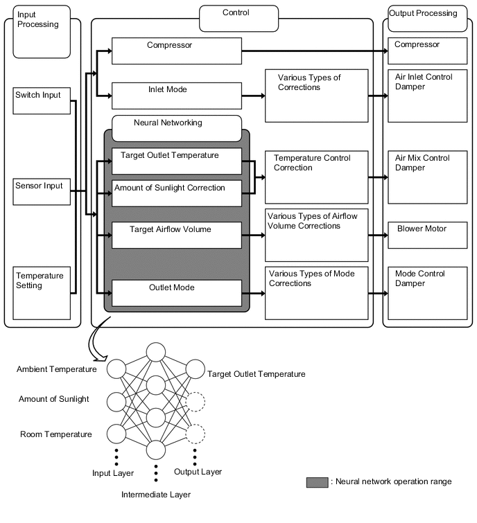
In the previous automatic air conditioning system, the air conditioning amplifier assembly determined the required outlet air temperature and blower air volume in accordance with a calculation formula that had been obtained based on information received from the sensors. However, because the sensors of a person are rather complex, a given temperature is sensed differently, depending on the environment in which the person is situated. For example, a given amount of solar radiation can feel comfortably warm in a cold climate, but extremely uncomfortable in a hot climate. Therefore, as a technique for effecting a high level of control, a neural network has been used in the automatic air conditioning system. With this technique, the data that has been collected under varying environmental conditions is stored in the air conditioning amplifier assembly, which effects control to provide enhanced air conditioning comfort.
-
The neural network control consists of neurons in an input layer, an intermediate layer, and an output layer. The input layer neurons process the input data of the ambient temperature, the amount of sunlight, and the room temperature based on the outputs of the switches and sensors, and output them to the intermediate layer neurons. Based on this data, the intermediate layer neurons adjust the strength of the links among the neurons. The sum of this data is then calculated by the output layer neurons in the form of the required outlet temperature, solar correction, target airflow volume, and outlet mode control volume. Accordingly, the air conditioning amplifier assembly controls the servo motors and blower with fan motor sub-assembly in accordance with the control volumes that have been calculated by the neural network control.
-
-
Refrigerant Volume Detection Control
-
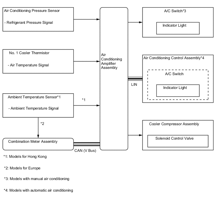
The air conditioning amplifier assembly judges the volume of refrigerant from the ambient temperature, refrigerant pressure and the temperature of the cool air past the No. 1 cooler evaporator sub-assembly. When the air conditioning amplifier assembly judges refrigerant shortage, it turns off the indicator light of the A/C switch. At that time, the cooler compressor assembly stops operating.
-
-
Quick Heater Control
-
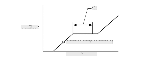
The on/off function of the quick heater assembly is controlled by the air conditioning amplifier assembly in accordance with the engine coolant temperature, engine speed, air mix setting, and electrical load (generator power ratio).
-
For example, the heating value of the operating quick heater assembly varies depending on the engine coolant temperature, as shown in the graph below:
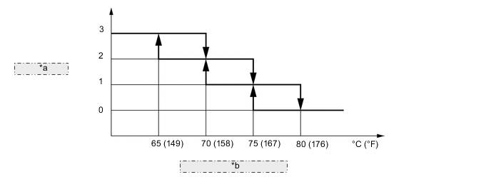
*a Heating Value *b Engine Coolant Temperature
-
-
Combustion Type Power Heater Control
-
Igniting
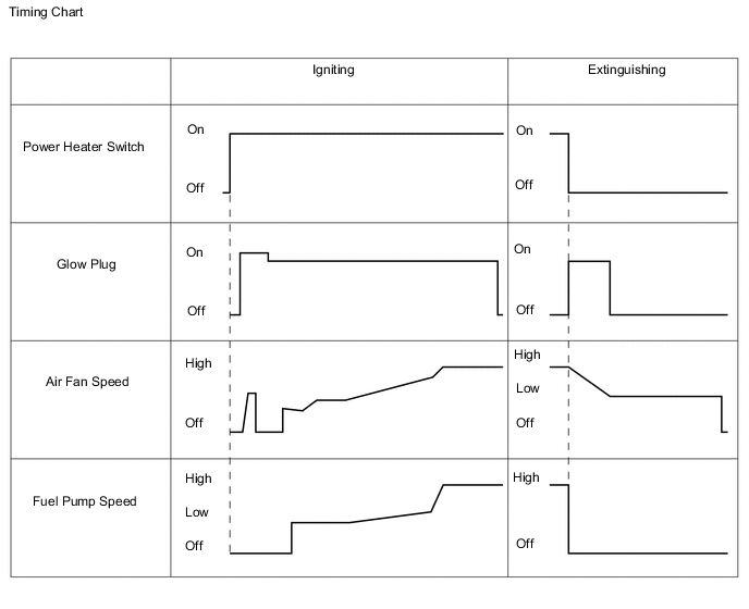
When the engine is operating, turning the power heater switch on causes the air fan to operate for several seconds for verification purposes. Then, the glow plug starts to preheat the combustion chamber. After that, the fuel pump and air fan turn on in order to start low combustion. The fuel pump speed is then increased in steps, and this is accompanied by a gradual increase in the speed of the air fan, thus leading to high combustion.
-
Extinguishing
When the ignition switch is turned off or the power heater switch is turned off, the fuel pump stops, causing the combustion to stop. For the purpose of after-purge, current is applied again to the glow plug, and the air fan is activated for several seconds. Then, the entire system comes to a stop.
-
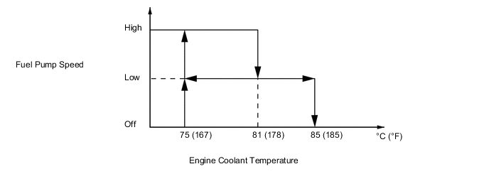
During Operation
While the system is in operation, it controls the fuel pump speed and switches between high combustion and low combustion, constantly keeping the engine coolant temperature between 75°C (167°F) and 85°C (185°F). If the engine coolant temperature exceeds 85°C (185°F), the fuel pump stops automatically to stop the combustion. Thereafter, when the engine coolant temperature reaches 75°C (167°F) or below, ignition occurs again. The operation of the glow plug, the air fan, and the fuel pump during extinguishing and re-igniting is the same as when these are operated by a switch as mentioned previously.
-
Protective Function
For self-protection, the combustion type power heater stops if an abnormal condition is detected. Descriptions of the function are indicated below:
Function Outline Dry Run Prevention If the temperature detected by the engine coolant temperature sensor or the overheating prevention sensor exceeds 125°C (257°F), the ECU determines that the heater is operating without water and automatically stops the system. Overheating Prevention If the difference in temperature detected by the engine coolant temperature sensor and the overheating prevention sensor exceeds 25°C (77°F), the ECU determines that the flow volume of the water is insufficient and automatically stops the system. Non-ignition or Misfiring Detection If the temperature of the exhaust gas detected by the flame sensor is low, the ECU determines that a non-ignition or a misfiring condition exists and automatically stops the system. Open or Short Circuit Detection If an open or short circuit exists in the sensors or actuators, the ECU automatically stops the system. Air Fan Seizure Detection If the air fan seizes, the ECU automatically stops the system.
-
-
Pollen Removal Mode Control
-
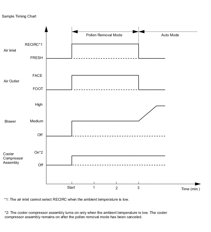
When the pollen removal mode switch is pressed, the pollen removal mode control is activated. Then, the air outlet is switched to the FACE mode and recirculated pollen-free air flows in the area around the upper part of the bodies of the driver and front passenger.
-
When the pollen removal mode switch signal is input to the air conditioning amplifier assembly, the air conditioning amplifier assembly controls the damper servo sub-assembly, blower with fan motor sub-assembly and cooler compressor assembly as shown in the timing chart below:
-
This control usually operates for approximately 3 minutes. However, when the ambient temperature is low (5°C [41°F] maximum), it will operate for approximately 1 minute.
-
After this control stops operating, the air conditioning amplifier assembly automatically returns to the mode it was in just before the pollen removal mode switch was pressed.
-
-
-
CONSTRUCTION
-
Air Conditioning Control Assembly
-
Air Conditioning Control Assembly (for Manual Air Conditioning)
-
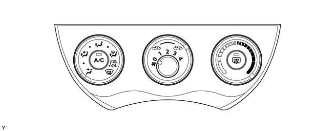
A rotary switch type air conditioning control assembly is used.
-
5 air outlet modes are provided on the control panel. To enable finer mode settings, a positive feel is provided between the positions of these modes, thus achieving a high comfort level.
-
A control cable is used. This cable is circular, and is placed around the cable pulleys that are provided at the air conditioning control assembly and the damper.
-
The operation effort of the air conditioning control assembly is transmitted to the damper via the control cable, which always moves in the pulling direction. Due to the consistent action point of the pulleys, the fluctuation of the operating effort has been minimized through the use of the pulleys. These measures have ensured ease of use and have reduced the operating effort.
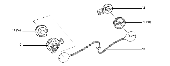
Text in Illustration *1 Pulley *2 Base of Pulley *3 Control Cable - - *a Air Conditioning Control Assembly Side *b Damper Side
-
-
Air Conditioning Control Assembly (for Automatic Air Conditioning)
-
A push button type air conditioning control assembly is used.
-
An air conditioning control assembly with Liquid Crystal Display (LCD) is used to ensure excellent visibility.
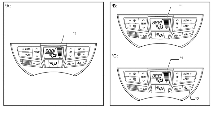
Text in Illustration *A LHD Models *B RHD Models *C Models with Pollen Removal Mode - - *1 LCD *2 Pollen Removal Mode Switch -
-
-
Air Conditioning Unit
-
The air conditioning unit consists of the heater radiator unit sub-assembly, No. 1 cooler evaporator sub-assembly, No. 1 cooler thermistor, blower with fan motor sub-assembly, clean air filter, quick heater assembly*1 and damper servo sub-assembly*2.
-
*1: Models with quick heater assembly
-
*2: Models with automatic air conditioning
-
-
A semi-center location air conditioning unit, in which the heater radiator unit sub-assembly and No. 1 cooler evaporator sub-assembly are placed in the vehicle's longitudinal direction, is used.
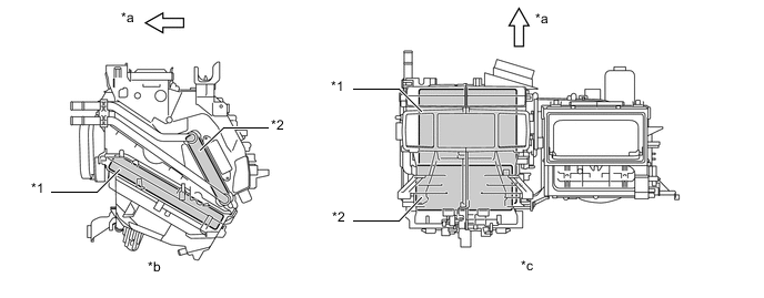
Text in Illustration *1 No. 1 Cooler Evaporator Sub-assembly *2 Heater Radiator Unit Sub-assembly *a Front *b Side View *c Top View - - -
A partial recirculation system is used. This system has an air inlet control door (sub) in the air inlet duct. Thus, it is able to cycle a small volume of recirculated air even in the FRESH mode, thus enhancing heating performance. When the blower switch is on, the suction force of the blower fan opens this air inlet control door (sub).
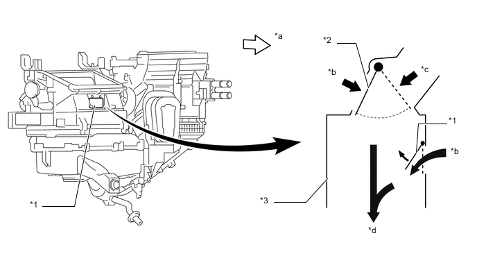
Text in Illustration *1 Air Inlet Control Door (Sub) *2 Air Inlet Control Door *3 Air Inlet Duct - - *a Front *b RECIRC *c FRESH *d To Blower Fan
-
-
No. 1 Cooler Evaporator Sub-assembly
-
A Revolutionary super-slim Structure (RS) evaporator is used. By placing the tanks at the top and the bottom of the No.1 cooler evaporator sub-assembly and by using a micropore tube construction, the following effects have been achieved:
-
Heat exchanging efficiency is ensured.
-
Temperature distribution is made uniform.
-
The No. 1 cooler evaporator sub-assembly is made thinner.
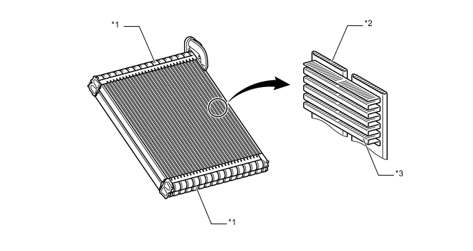
Text in Illustration *1 Tank *2 Micropore Tube *3 Cooling Fin - - -
-
-
No. 1 Cooler Thermistor
-
The No. 1 cooler thermistor detects the temperature of the cool air immediately past the No. 1 cooler evaporator sub-assembly in the form of resistance changes, and outputs it to the air conditioning amplifier assembly.
-
-
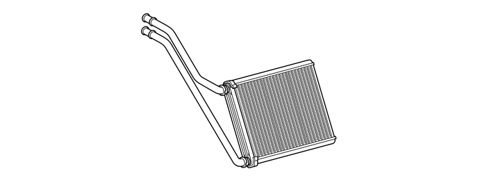
Heater Radiator Unit Sub-assembly
-
The heater radiator unit sub-assembly has been made more compact and performance has been improved by making the core section finer and improving the shapes of the tank section and flow section. Also, the environment has been considered. By using aluminum as the material, the amount of the environmental burden disposal (lead) has been reduced.
-
-
Blower with Fan Motor Sub-assembly
-
High magnetic force magnets and ball bearings are used to achieve a compact and lightweight assembly.
-
-
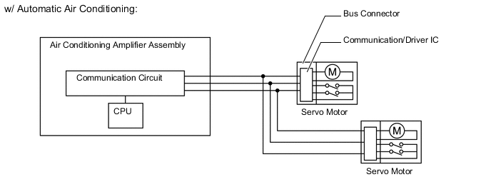
Bus Connector
-
The bus connector has a built-in communication/driver IC, which communicates with each servo motor connector, actuates the servo motor, and has a position detection function. This enables bus communication for the servo motor wire harness to achieve a more lightweight construction and a reduced number of wires.
-
-
Servo Motor
-
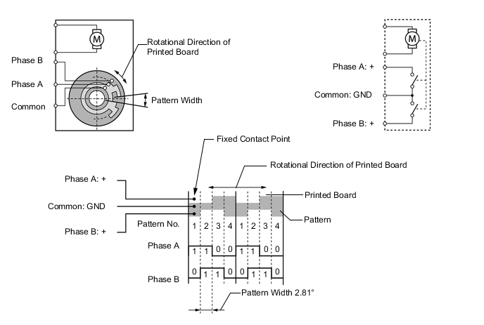
In contrast to the previous type that detects the position by way of a potentiometer voltage, the pulse pattern type servo motor detects the relative position by way of the 2-bit on/off signals.
-
The forward and reverse revolutions of this motor are detected by way of 2 phases, A and B, which output 4 types of patterns. The air conditioning amplifier assembly counts the number of pulse patterns in order to determine the stopped position.
-
-
Cooler Condenser Assembly
-
A sub-cool condenser is used. This is a multi-flow condenser consisting of 3 portions: a condensing portion, a super-cooling portion and a gas-liquid separator (modulator) all integrated together. This cooler condenser assembly uses a sub-cool cycle for its cooling cycle system to improve heat-exchanging efficiency.
-
In the sub-cool cycle, after the refrigerant passes through the condensing portion of the cooler condenser assembly, both the liquid refrigerant and the gaseous refrigerant that could not be liquefied are cooled again in the super-cooling portion. Thus, the refrigerant is sent to the No. 1 cooler evaporator sub-assembly in an almost completely liquefied state.
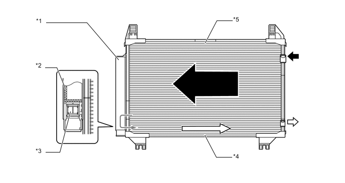
Text in Illustration *1 Modulator *2 Desiccant *3 Filter *4 Super-cooling Portion *5 Condensing Portion - - 
Gaseous Refrigerant 
Liquid Refrigerant Tech Tips
The point at which the air bubbles disappear in the refrigerant of the sub-cool cycle is lower than the proper amount of refrigerant with which the system must be filled. Therefore, if the system is recharged with refrigerant based on the point at which the air bubbles disappear, the amount of refrigerant would be insufficient. As a result, the cooling performance of the system will be affected. If the system is overcharged with refrigerant, this will also lead to reduced performance. For the proper method of verifying the amount of the refrigerant and to recharge the system with refrigerant, refer to the Repair Manual.
*1 Properly Recharged Amount *2 High Pressure *3 Point at which Bubbles Disappear *4 Amount of Refrigerant
-
-
Cooler Compressor Assembly
-
The cooler compressor assembly is a continuously variable capacity type with a capacity that varies in accordance with the cooling load of the air conditioning.
-
The cooler compressor assembly consists of the shaft, lug plate, piston, shoe, crank chamber, cylinder and solenoid control valve.
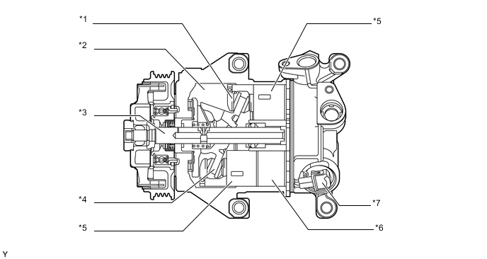
Text in Illustration *1 Shoe *2 Crank Chamber *3 Shaft *4 Lug Plate *5 Piston *6 Cylinder *7 Solenoid Control Valve - - -
A variable suction side throttle is used.
-
Refrigerant inlet pressure is applied to the top of the variable suction side throttle and crank chamber pressure to the bottom of the variable suction side throttle.
-
The pressure difference moves the variable suction side throttle up and down, expanding and contracting the refrigerant inlet passage.
-
When the refrigerant flow is at a maximum, the refrigerant inlet pressure is greater than the crank chamber pressure. This causes the variable suction side throttle to move down, fully opening the refrigerant inlet passage and lowering the refrigerant inlet resistance.
-
When the amount of refrigerant flow is controlled, the crank chamber pressure is greater than the refrigerant inlet pressure, raising the variable inlet throttle to contract the flow passage.
-
These controls suppress noise by reducing pulsation from the refrigerant inlet.
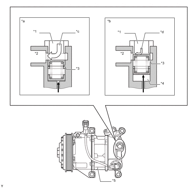
Text in Illustration *1 Refrigerant Passage A *2 Inlet Chamber *3 Variable Suction Side Throttle *4 Crank Pressure Inlet Chamber *5 Cooler Compressor Assembly - - *a With Maximum Volume of Refrigerant *b With Controlled Volume of Refrigerant *c High Flow *d Low Flow Crank Chamber Pressure Refrigerant Flow -
-
A Damper Limiter (DL) type air conditioning pulley is used. A cylinder-type damper is used for the this cooler compressor assembly and the torque fluctuations have been suppressed, thus making the inertia weight unnecessary. As a result, the weight of the cooler compressor assembly has been reduced.
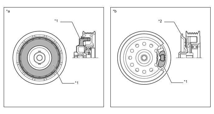
Text in Illustration *1 Damper *2 Inertia Weight *a 5TSE10C Cooler Compressor Assembly *b Conventional Type Cooler Compressor Assembly
-
-
Clean Air Filter
-
A high efficiency type clean air filter is used to remove dust, pollen, and other micron particles from air entering from outside the vehicle to provide a comfortable cabin of clean air. The clean air filter is installed in the upper section of the blower fan.
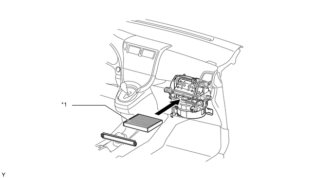
Text in Illustration *1 Clean Air Filter - - Tech Tips
See the table below regarding the replacement intervals for the high efficiency type clean air filter. Replace the clean air filter after the ignition switch has been turned off.
Condition Destination Europe Others Normal Condition 30000 km (18000 miles) 20000 km (12000 miles) Dusty Condition 15000 km (9000 miles) 15000 km (9000 miles)
-
-
Quick Heater Assembly
-
The quick heater assembly is located above the heater radiator unit sub-assembly in the air conditioning unit.
-
The quick heater assembly consists of a Positive Temperature Coefficient (PTC) element, an aluminum fin and a brass plate. When current is applied to the PTC element, it generates heat to warm the air that passes through the unit.
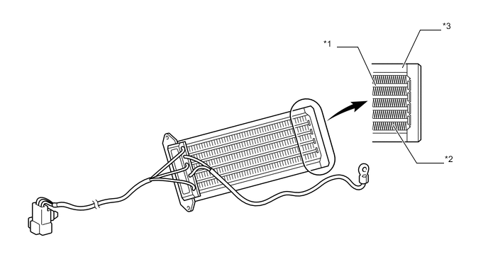
Text in Illustration *1 PTC Element *2 Aluminum Fin *3 Brass Plate - -
-
-
Combustion Type Power Heater
-
The combustion type power heater assembly consists mainly of a heater exchanger, a glow plug, a blower motor, an air fan, an ECU, an engine coolant temperature sensor, an overheating prevention sensor, a flame sensor, an intake pipe, an exhaust pipe and a fuel pump.
-
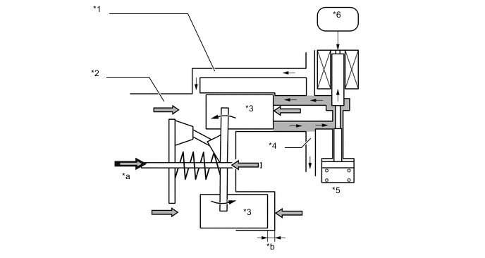
This heater is installed between the engine and heater radiator unit sub-assembly. The engine coolant from the engine flows through the spiral passage around the heat exchanger and flows into the heater radiator unit sub-assembly. At this time, the glow plug ignites the air and fuel in the combustion chamber of the heat exchanger, and the resultant heat of combustion heats the engine coolant.
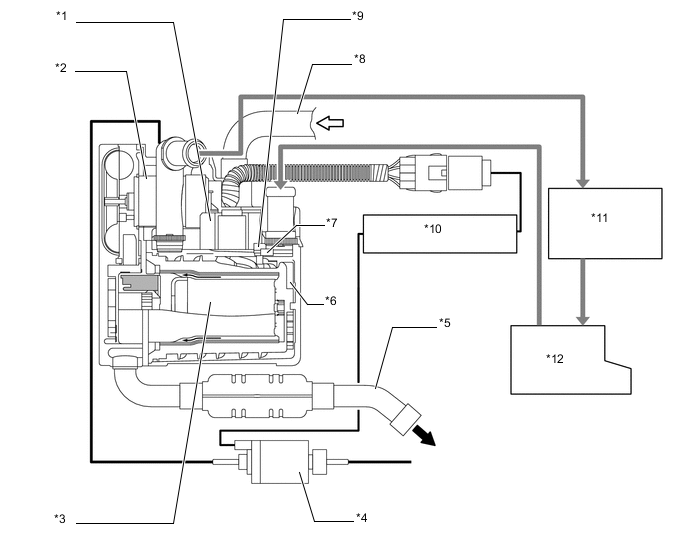
Text in Illustration *1 ECU *2 Blower Motor *3 Combustion Chamber *4 Fuel Pump Assembly *5 Exhaust Pipe *6 Heat Exchanger *7 Overheating Prevention Sensor *8 Intake Pipe *9 Engine Coolant Temperature Sensor *10 Power Heater Switch *11 Heater Radiator Sub-assembly *12 Engine Intake Air Exhaust Gas 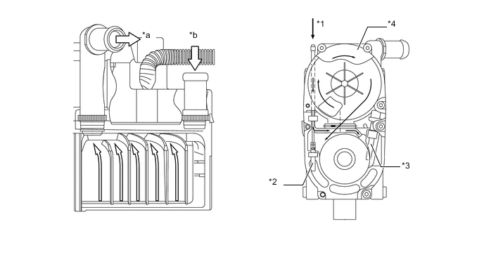
Text in Illustration *1 Fuel *2 Flame Sensor *3 Glow Plug *4 Air Fan *a To Heater Radiator Unit Sub-assembly *b From Engine Engine Coolant Flow - -
-
-
Ambient Temperature Sensor
-
The ambient temperature sensor detects the ambient temperature based on changes in the resistance of its built-in thermistor. This signal is used by the air conditioning amplifier assembly.
-
-
Air Outlet Temperature Sensor
-
The air outlet temperature sensor detects the air outlet temperature of the driver footwell register duct based on changes in the resistance of its built-in thermistor. This signal is used by the air conditioning amplifier assembly.
-
-
Room Temperature Sensor
-
The room temperature sensor detects the room temperature based on changes in the resistance of its built-in thermistor. This signal is used by the air conditioning amplifier assembly.
-
-
Automatic Light Control Sensor
-
The automatic light control sensor detects (in the form of changes in the current that flows through the built-in photo diode) the changes in the amount of sunlight and outputs these sunlight strength signals to the air conditioning amplifier assembly.
-
-
-
OPERATION
-
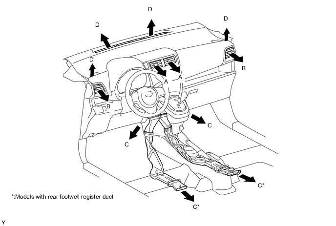
Mode Position and Damper Operation
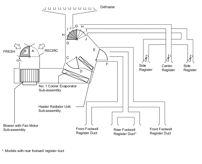
Control Damper Operation Position Damper Position Operation Air Inlet Control Damper FRESH A Brings in fresh air. RECIRC B Recirculates internal air. Air Mix Control Damper MAX COLD to MAX HOT C - D Varies the mixture ratio of the cold air and the hot air in order to regulate the temperature continuously from HOT to COLD. Mode Control Damper 
FACE E, G Air blows out of the center register and side register. 
BI-LEVEL F, G Air blows out of the center register, side register, front footwell register duct and rear footwell register duct*. 
FOOT F, I Air blows out of the front footwell register duct and rear footwell register duct*. In addition, air blows out slightly from the side register and the defroster. 
FOOT/DEF F, H Air blows out of the defroster, side register, front footwell register duct and rear footwell register duct*. 
DEF E, J Air blows out of the defroster and side register.
-
*: Models with rear footwell register duct
-
-
Air Outlets and Airflow Volume
Indication Mode A B C D Center Side Front Footwell/Rear Footwell* Defroster FACE 
- - BI-LEVEL 
- FOOT - 
FOOT/DEF - DEF - -
-
*: Models with rear footwell register duct
-
-
Cooler Compressor Operation
-
The crank chamber is connected to the suction passage. A solenoid control valve is provided between the suction passage (low pressure) and the discharge passage (high pressure).
-
The solenoid control valve operates under duty cycle control in accordance with the signals from the air conditioning amplifier assembly.
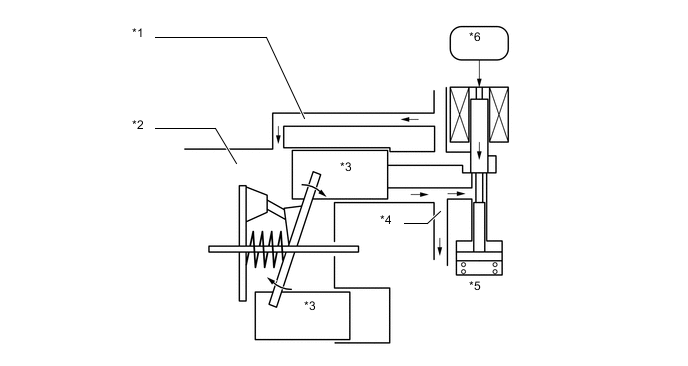
Text in Illustration *1 Suction Passage *2 Crank Chamber *3 Piston *4 Discharge Passage *5 Solenoid Control Valve *6 Air Conditioning Amplifier Assembly -
When the solenoid control valve closes (the solenoid coil is energized), a difference in pressure is created and the pressure in the crank chamber decreases. Then, the pressure applied to the right side of the piston becomes greater than the pressure applied to the left side of the piston. This compresses the spring and tilts the lug plate. As a result, the piston stroke increases and the discharge capacity increases.
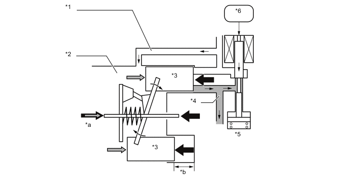
Text in Illustration *1 Suction Passage *2 Crank Chamber *3 Piston *4 Discharge Passage *5 Solenoid Control Valve *6 Air Conditioning Amplifier Assembly *a Crank Chamber Pressure + Spring Force *b Piston Stroke: Large -
When the solenoid control valve opens (the solenoid coil is not energized), the difference in pressure disappears. Then, the pressure applied to the left side of the piston becomes the same as the pressure applied to the right side of the piston. Thus, the spring elongates and eliminates the tilt of the lag plate. As a result, there is a small piston stroke and the discharge capacity decreases.
Text in Illustration *1 Suction Passage *2 Crank Chamber *3 Piston *4 Discharge Passage *5 Solenoid Control Valve *6 Air Conditioning Amplifier Assembly *a Crank Chamber Pressure + Spring Force *b Piston Stroke: Small
-
-
-
DIAGNOSIS
-
The air conditioning amplifier assembly has a self-diagnosis function. It stores any operation failures in the air conditioning system memory in the form of DTCs. For details, refer to the Repair Manual.
-
If a malfunction occurs in the system, it is possible to access the DTC by using SST that has been designed exclusively for the combustion type power heater. For details, refer to the Repair Manual.
-