AIR CONDITIONING SYSTEM
-
OUTLINE
-
Manual air conditioning or automatic air conditioning is used.
-
A partial recirculation system is used. This improves heating performance.
-
A quick heater assembly or combustion type power heater is used on the cold area specification models.
-
-
SPECIFICATION
-
Performance
Heater Heater Output 4600 W (3950 kcal/h)
4700 W (4040 kcal/h)*1
Air Flow Volume 280 m3/h
290 m3/h*1
Power Consumption 170 W Air Conditioning Cooling Capacity 4400 W (3780 kcal/h)
4500 W (3870 kcal/h)*2
Air Flow Volume 420 m3/h
460 m3/h*2
Power Consumption 210 W
230 W*2
-
*1: Models with quick heater assembly
-
*2: LHD models with manual air conditioning
-
-
Ventilation and Heater Radiator
Ventilation and Heater Radiator Heater Radiator Unit Sub-assembly Type Straight Flow Aluminum-II (SFA-II) Size
W x H x L
201.5 mm x 140 mm x 27 mm
(7.9 in. x 5.5 in. x 1.1 in.)
Fin Pitch 1.8 mm (0.07 in.) Blower with Fan Motor Sub-assembly Motor Type K62-12.5T
K62-11.5T*
Fan Type Semi Sirocco Fan Size
Dia. x H
145 mm x 65 mm (5.7 in. x 2.6 in.)
-
*: LHD models with manual air conditioning
-
-
Air Conditioning
Air Conditioning Cooler Condenser Assembly Type Multi-Flow-IV (MF-IV) Sub-cool Size
W x H x L
520 mm x 325.4 mm x 16 mm
(20.5 in. x 12.8 in. x 0.6 in.)
Fin Pitch 2.75 mm (0.1 in.) No. 1 Cooler Evaporator Sub-assembly Type Revolutionary Super-slim Structure (RS) Size
W x H x L
199.3 mm x 231 mm x 38 mm
(7.8 in. x 9.1 in. x 1.5 in.)
Fin Pitch 2.6 mm (0.1 in.) Cooler Compressor Assembly Type 5TSE10C Pulley Damper Limiter (DL) Pulley Refrigerant Type R134a Charge Volume 360 g +/- 30 g
-
-
MAIN FEATURES
-
The following parts are used to ensure high cooling performance while achieving a compact and lightweight construction:
-
Semi-center Location Air Conditioning Unit
-
Revolutionary Super-slim Structure (RS) Evaporator
-
Straight Flow Aluminum-II (SFA-II) Heater Radiator
-
Multi-Flow-IV (MF-IV) Sub-cool Condenser
-
-
A refrigerant volume detection control is used. When a shortage of refrigerant is detected, the indicator light of the A/C switch is turned off to inform the user of the refrigerant shortage.
-
A variable suction side throttle is used on the cooler compressor assembly. The variable suction side throttle suppresses noise by reducing pulsation from the refrigerant inlet.
-
The combustion type power heater is provided between the engine and the heater radiator unit sub-assembly. Air and fuel are introduced into the heater's combustion chamber, and a glow plug is used to ignite this mixture. By heating the engine coolant that flows around the combustion chamber, this system ensures the heating effect. The system can be activated or deactivated by turning on or off the power heater switch.
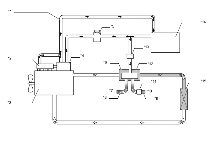
Text in Illustration *1 Fuel Return Pipe *2 Common-Rail *3 Engine *4 Supply Pump *5 Fuel Filter *6 Combustion Type Power Heater *7 Intake Air *8 Intake Pipe *9 Exhaust Pipe *10 Exhaust Gas *11 Muffler *12 Combustion Chamber *13 Fuel Pump *14 Fuel Tank *15 Heater Radiator Unit Sub-assembly - - 
Fuel 
Engine Coolant Tech Tips
-
When the power heater is turned on or off, some white smoke and a slight odor may be emitted from the exhaust located under the floor.
-
If the power heater is being used under extremely cold conditions, vapor may be visible from the exhaust.
-
It is not recommended to restart the power heater for 10 minutes after the power heater is turned off. Otherwise, a noise may be heard as the heater ignites.
-
Do not turn the power heater on and off repeatedly within 5-minute intervals as this can shorten the life of the heater components.
-
If the engine is to be turned on and off repeatedly within short intervals (such as when being used for delivery purposes), turn the power heater switch off.
-
-