METER / GAUGE SYSTEM
-
OUTLINE
-
An analog display type combination meter assembly is used.
-
A multi-information display whose display items can be changed by pressing the ODO/TRIP DISP switch and shift position indicator lights are provided in the Liquid Crystal Display (LCD) on the center section of the combination meter assembly.
-
An ECU and buzzer are enclosed in the combination meter assembly. This ECU maintains communication with other ECUs through the CAN.
-
An oil change reminder indicator light is used to urge the driver to change the engine oil.
-
A dimming mode display function has been provided. In order to adjust the combination meter assembly luminance, the illumination brightness level is indicated on the multi information display.
-
The stop and start indicator and stop and start cancel indicator lights inform the driver of the stop and start system operating condition. For details, see the stop and start system.
-
The gear shift indicator, which recommends the driver to shift the lever for eco-friendly driving, is used. For details, see the EC63/EC65 manual transaxle.
-
The rear seat belt warning has been located on the center of the instrument panel.
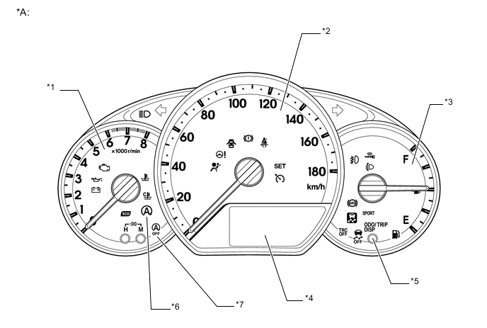
Text in Illustration *A Models for Hong Kong - - *1 Tachometer *2 Speedometer *3 Fuel Gauge *4 Multi-information Display *5 ODO/TRIP DISP Switch *6 Stop and Start Indicator Light *7 Stop and Start Cancel Indicator Light - - 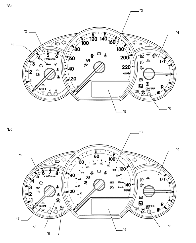
Text in Illustration *A Models with 1ND-TV Engine *B Models with 1NR-FE Engine *1 Oil Change Reminder Indicator Light *2 Tachometer *3 Speedometer *4 Fuel Gauge *5 Multi-information Display *6 ODO/TRIP DISP Switch *7 Gear Shift Indicator *8 Stop and Start Indicator Light *9 Stop and Start Cancel Indicator Light - - -
-
PRECAUTION
-
Ignition Switch Expressions
-
The type of ignition switch used on this model differs depending on the specifications of the vehicle. The expressions listed in the table below are used in this section.
Expression Ignition Switch (Ignition or Starter Switch Assembly)
(Position)
Engine Switch (Push Start Switch)
(Condition)
Ignition Switch off LOCK Off Ignition Switch ACC ACC On (ACC) Ignition Switch ON ON On (IG) Engine Start START Start
-
-