CHARGING SYSTEM
-
SYSTEM CONTROL
-
This system lowers the generated voltage when the vehicle is accelerating, and raises the generated voltage when the vehicle is decelerating. This reduces the load applied to the engine by the generator while it is generating electricity, resulting in improved fuel economy. During idle or constant-speed driving, this system regulates the generated voltage in order to bring the amperage estimation value closer to the target value.
-
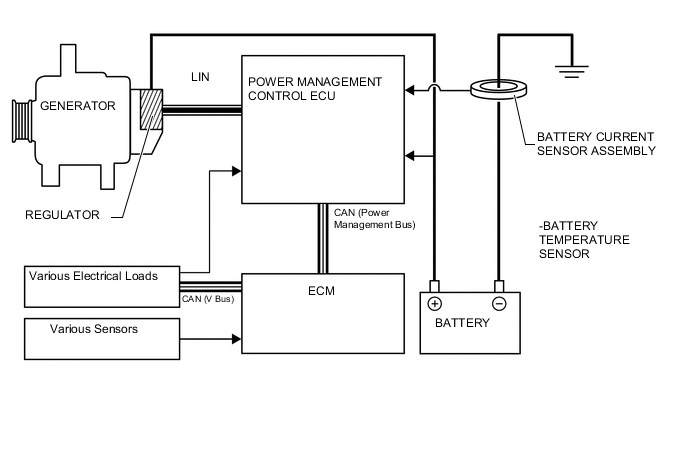
This control consists of the ECM, power management control ECU, battery current sensor with a built-in battery temperature sensor, an alternator, and various sensors and switches.
-
The ECM detects the driving conditions based on the signals output by various sensors and switches. To give voltage instructions to the generator, the power management control ECU performs calculations based on battery voltage as well as the signals output by the battery current sensor and the battery temperature sensor.
-
The ECM stops the charging control and the generator switches to normal power generation mode under the following conditions:
-
Low battery capacity
-
Low or high battery temperature
-
Wipers operating or blower motor operating with taillight relay ON
-
Battery current sensor assembly or battery temperature sensor malfunctions
-
Engine started
-
Battery charged for approximately 3 to 3.5 hours
-
Accumulated driving time becomes approximately 20 hours
-
CAN communication error
-
-
-
CONSTRUCTION
-
Generator
-
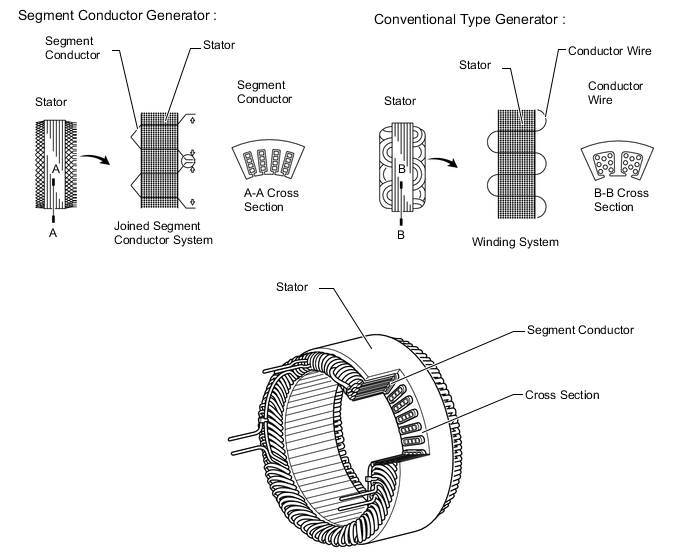
This generator has a joined segment conductor system in which multiple segment conductors are welded together to form the stator. Compared to the conventional winding system, the electrical resistance is reduced due to the shape of the segment conductors, and their arrangement helps to make the generator compact.
-
-
Battery Current Sensor Assembly
-
Installed on the negative terminal of the battery, this sensor detects the amount of charging and discharging amperage of the battery and sends signal to the power management control ECU. Based on this signal, the power management control ECU calculates the battery capacity.
-
A Hall IC is used for detecting the amount of charging and discharging amperage. The changes that occur in the magnetic flux density in the core as a result of the charging and amperage of the battery are converted and output as voltage.
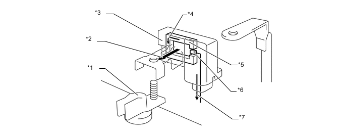
Text in Illustration *1 Negative Terminal of the Battery *2 Charge/discharge Current *3 Battery Current Sensor Assembly *4 Magnetic Field *5 Core *6 Hall IC *7 Charge/discharge Amount Signals - - 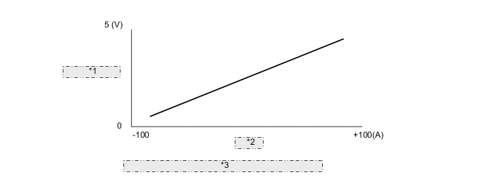
*1 Output Voltage *2 Current *3 Characteristic of BATTERY CURRENT SENSOR ASSEMBLY
-
-
Battery Temperature Sensor
-
The battery temperature sensor is built into the battery current sensor assembly.
-
The battery characteristic (battery internal resistance) of taking in current for charging varies according to battery electrolyte temperature. If the electrolyte temperature is too low or too high, the battery internal resistance will increase, resulting in early deterioration. To prevent this, the battery temperature sensor changes its resistance as shown below to detect the temperature.
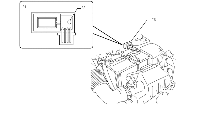
Text in Illustration *1 Battery Current Sensor Assembly Cross Section *2 Battery Temperature Sensor Portion *3 Battery Current Sensor Assembly - - 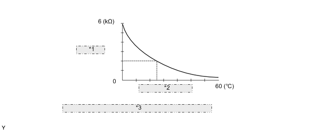
*1 Resistance *2 Battery Temperature *3 Characteristic of BATTERY TEMPERATURE SENSOR ASSEMBLY
-
-