MONITOR SYSTEM
-
OPERATING CONDITION
-
Rear view monitor system operates the following conditions are met:
-
The ignition switch (engine switch*) ON
-
The shift lever is moved to R
-
The back door completely closed
Tech Tips
*:Models with entry and start system
-
-
-
FUNCTION OF MAIN COMPONENTS
Component Function Radio Receiver Assembly Displays the image transmitted by the rear television camera assembly on the screen. Rear Television Camera Assembly Captures images in rear of the vehicle and outputs visual signals to the radio receiver assembly display. Park/Neutral Position Switch Assembly*1 Transmits the shift position signal to the ECM. Back-up Light Switch Assembly*2 Transmits the reverse position signal to the ECM. Main Body ECU (Multiplex Network Body ECU) Outputs the back door courtesy switch signal to the radio receiver assembly. ECM Outputs the shift position signal to the radio receiver assembly. Back Door Lock Assembly (Back Door Courtesy Switch) Detects whether the back door is opened or closed.
-
*1: Models with CVT
-
*2: Models with manual transmission or multi-mode manual transmission
-
-
FUNCTION
-
Area Displayed on Screen
-
Television Camera Assembly
-
On the display, objects on the right of the vehicle appear on the right side of the display panel, and objects on the left of the vehicle appear on the left side of the display panel.
-
The television camera uses a wide-angle lens. The perceived distance from images that appear on the screen differs from the actual distance.
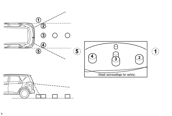
Tech Tips
The area displayed on the screen may vary in accordance with vehicle status or road conditions. The area covered by the television camera is limited. The television camera does not show objects close to either corner of the bumper or under the bumper.
-
-
-
-
CONSTRUCTION
-
Rear Television Camera Assembly
The rear television camera assembly consists of a wide-angle lens and a Complementary Metal Oxide Semiconductor (CMOS).
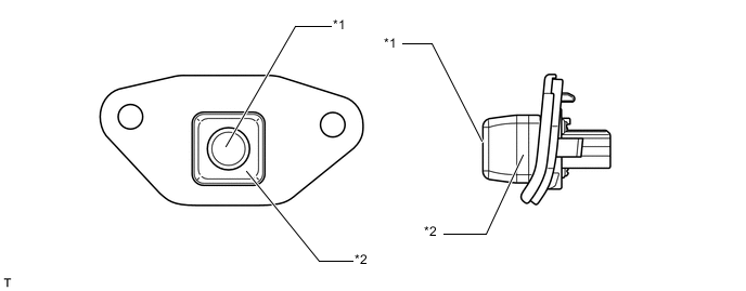
Text in Illustration *1 Wide-angle Lens *2 Rear Television Camera Assembly -
Display (Rear View Monitor Display)
-
When reverse is selected, the display shows the image from the rear television camera assembly.
-
When the display shows the image of the area behind the vehicle, the parking guide lines are also displayed.
-
A description of the parking guide line mode display is provided in the following diagram.
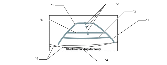
Item Description *1 Vehicle Width Extension Guide Lines (Blue) Indicate the estimated vehicle width. *2 Vehicle Center Guide Lines (Blue) These lines indicate the estimated position on the ground of the center of the vehicle. *3 Distance Guide Line (Red) Indicates a position on the ground approximately 0.5 m (1.6 ft.) behind the rear bumper. *4 Warning Message Display Area Area where warning messages are displayed. *5 Rear Bumper The bumper and outer panel rear edge are shown in the rear view monitor display. *6 Distance Guide Line (Blue) Indicates a position on the ground approximately 1.0 m (3.3 ft.) behind the rear bumper. Tech Tips
Each parking guide line does not change even if the steering is turned.
-
-