BRAKE SYSTEM
-
CONSTRUCTION
-
Brake Assist Mechanism
-
The brake assist mechanism consists of the slide valve, slide valve hook, air valve, control valve and operation rod in the brake booster.
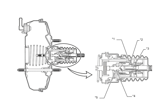
Text in Illustration *1 Control Valve *2 Air Valve *3 Operation Rod *4 Slide Valve *5 Slide Valve Hook - -
-
-
-
OPERATION
-
Brake Assist Mechanism
-
With no braking condition, the air valve is closed, and the pressure in the variable pressure chamber is the same as the constant pressure chamber.
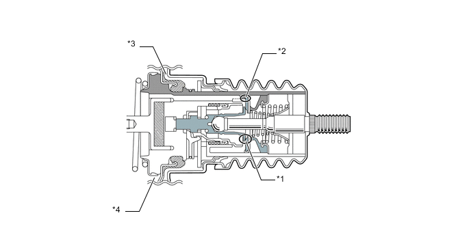
Text in Illustration *1 Air Valve "Close" *2 Control Valve "Close" *3 Variable Pressure Chamber *4 Constant Pressure Chamber -
During normal braking, the air valve opens to activate the brake booster function.
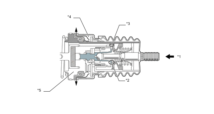
Text in Illustration *1 Push *2 Air Valve "Open" *3 Control Valve "Closed" *4 Variable Pressure Chamber *5 Power Piston - - -
When the operation rod speed is faster than the power piston speed, the air valve pushes the slide valve hook. Consequently, the slide valve separates from the slide valve hook, and the slide valve pushes the control valve to open the air valve wider than in the normal brake condition. Thus, the air volume that is introduced increases. This forcefully pushes the power piston resulting in a greater brake assist force.
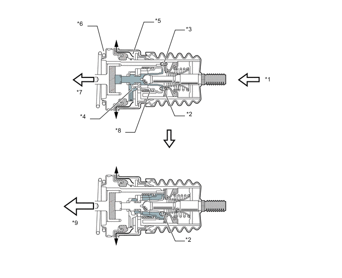
Text in Illustration *1 Push *2 Air Valve "Open" *3 Control Valve "Closed" *4 Slide Valve Hook *5 Variable Pressure Chamber *6 Constant Pressure Chamber *7 Move *8 Slide Valve *9 More Move - -
-
-