STOP AND START
-
FUNCTION OF MAIN COMPONENTS
Component Function Engine Stop and Start ECU
- Backup Boost Converter*1
Sends either an engine stop or restart signal to the ECM according to the signals from each sensor and switch. Backup Boost Converter
(Eco Run Vehicle Converter Assembly)*2
-
Supplies battery voltage to help make up for the voltage drop that occurs when the engine is restarted, preventing the operation of various systems from being interrupted due to low battery voltage.
-
Supplies battery voltage to the oil pump with motor assembly.*3
Oil Pump with Motor Assembly*3 Holds the CVT oil pressure while idle stop. This integrates the oil pump motor driver. Clutch Upper Switch*4 Recognizes that the clutch pedal is not depressed and sends a signal to the engine stop and start ECU. Clutch Lower Switch*4 Recognizes that the clutch pedal is depressed and sends a signal to the engine stop and start ECU. Neutral Position Switch*4 Recognizes that the shift lever is in N and sends a signal to the engine stop and start ECU. Park/Neutral Position Switch Assembly*3 Recognizes that the shift lever position and sends a signal to the engine stop and start ECU. Engine Oil Pressure Switch Assembly The system prevents the oil pressure warning light in the combination meter assembly from illuminating when the engine is stopped due to stop and start system control. Blower Temperature Sensor*2 Detects the temperature of air from the blower and sends a signal to the engine stop and start ECU. Vacuum Sensor Assembly Detects the brake booster vacuum pressure and sends a signal to the engine stop and start ECU. Engine Hood Courtesy Switch Detects whether the hood is open or closed and sends a signal to the engine stop and start ECU. Front Door Courtesy Light Switch Assembly (Driver) Detects whether the door is open or closed and sends a signal to the engine stop and start ECU via the main body ECU via CAN communication. Front Seat Belt Buckle Switch (Driver)*3 Detects whether or not the driver's seat belt has been fastened, and sends a signal to the engine stop and start ECU via the main body ECU (multiplex network body ECU) via CAN communication. Battery Current Sensor Assembly (Included in Battery Temperature Sensor) Detects the battery temperature and how much power is being charged to or discharged from the battery and sends signals to the engine stop and start ECU. These signals are used to protect the battery. Air Conditioning Amplifier Assembly Blower Switch Sends a blower operation signal to the engine stop and start ECU. Combination Meter Assembly Stop and Start Indicator Light
-
Turns on when the engine is stopped due to stop and start system control.
-
If a system malfunction is detected, the stop and start indicator light blinks to inform the driver.
Stop and Start Cancel Indicator Light
-
Turns on to inform the driver that the system has been disabled when.
-
Stop and start system operation is prohibited by stop and start cancel switch.
Multi-information Display (Eco Odo Display) Displays the total amount of engine stoppage time occurring since the last reset. Stop and Start System Cancel Switch Assembly (Telltale Light Assembly) The operation of the system can be cancelled by pressing the stop and start system cancel switch. Pressing the switch again or turning the power source off and back on restores the operation of the system. ECM Sends various information about engine conditions to the engine stop and start ECU. Skid Control ECU Sends a vehicle speed signal to the engine stop and start ECU. Airbag Sensor Assembly Sends airbag deployment information in the event of a collision and deceleration signal to the engine stop and start ECU. Tech Tips
*1: Models with 1NZ-FE Engine
*2: Models with 1NR-FE Engine
*3: Models with CVT
*4: Models with M/T
-
-
FUNCTION
-
Stop and Start System Function Setting*
-
By pressing and holding the stop and start system cancel switch assembly, the period for idling stop can be switched between normal and stop and start system priority .
-
-
Stop and Start System Cancel Function Activated by Steering Wheel Operation
-
If the steering wheel is turned with a speed of 45° per second or more, the idling stop function will not be executed even if the idling stop conditions are met such as when the vehicle is stopped.
-
The engine starts turning if the steering wheel is turned 25° or more when the engine is stopped by the stop and start system.
-
Tech Tips
*: Models with 1NZ-FE Engine
-
-
OPERATING CONDITION
-
Operating Conditions at Engine Stop and Restart
-
The engine may stop if all of these conditions are detected.
Operating Condition (Models with 1NR-FE Engine) Item Operating Condition Idle Stop Engine Coolant Temperature 40°C to 105°C (104°F to 221°F) CVT Oil Temperature*1 25°C to 100°C (77°F to 212°F) Driver Door Closed Brake Booster Vacuum Sufficient brake booster vacuum Stop and Start System Cancel Switch Off condition Road Gradient*1 8° or less Vehicle Speed
-
0 km/h (0 mph)
-
Vehicle has been driven at 7 km/h (4.4 mph) or more (first operation of control only, second operation of control is 3 km/h (1.9 mph) or more).
Engine Speed 1200 rpm or less Clutch Pedal*2 Released Shift Lever Position N, P*1, D*1 Driver's Seat Belt*1 Fastened Engine Hood Closed Battery Voltage
-
7.6 V or more at engine start and 8.16 V or more at engine cranking.*1 (49 msec after engine start)
-
7.6 V or more at engine start.*2
Battery Temperature -15°C to 75°C (5°F to 167°F) Battery Integrated Current*3
-
0 A-sec or more: After engine start by ignition switch operation
-
After the integrated current value has increased to 0 A-sec or more at least once ignition switch ON:
-
More than -3564 A-sec*1 (-3110 A-sec*2): When a low battery temperature condition is not detected (the battery temperature is 11°C (52°F) or more).
-
More than -990 A-sec*1 (-864 A-sec*2): When a low battery temperature condition is not detected (the battery temperature is less than 10°C (50°F)).
Air Conditioning Off or on with an outside temperature of 25°C (77°F) or lower and an evaporator temperature of 8°C (46°F) or lower. Heater Off or on with an outside temperature of 10°C (50°F) or higher and an engine coolant temperature of 55.5°C to 65.5°C (132°F to 150°F) or higher. ECM Learning Completed Tech Tips
*1: Models with CVT
*2: Models with M/T
*3: Regarding Battery Integrated Current
In the stop and start system, the engine stop and start ECU switches the system control mode (stop and start system control permitted/prohibited) based on the battery condition (charge/discharge condition) to protect the battery and to ensure stable engine restarting performance.
The battery charge-discharge condition is determined from the integrated current value calculated from the battery current sensor signal. The integrated current value is obtained by multiplying the current (ampere) detected from the battery current sensor assembly by the time (seconds), and it is expressed in the unit A-sec. This can be measured by Global TechStream (GTS).
The engine stop and start ECU determines the power charge based on the integrated current value, and it prohibits stop and start system control if the value is below the threshold, because the battery might not be able to start the engine. The threshold values according to the battery temperature and battery charge condition.
Operating Condition (Models with 1NZ-FE Engine) Item Operating Condition Idle Stop Engine Coolant Temperature 40°C to 105°C (104°F to 221°F) CVT Oil Temperature 25°C to 110°C (77°F to 230°F) Driver Door Closed Brake Booster Vacuum Sufficient brake booster vacuum Stop and Start System Cancel Switch Off condition Road Gradient 8° or less Vehicle Speed 0 km/h (0 mph) Engine Speed 1200 rpm or less Throttle opening angle 0 Shift Lever Position N, P, D After operating the shift lever At least 1 second elapsed After turning the ignition switch on At least 5 seconds elapsed Driver's Seat Belt Fastened Engine Hood Closed Battery Voltage The voltage at the time of starting engine is 8.14 V or more and the minimum voltage after the starter is launched and the engine is cranked is 7.6 V or more. Battery Temperature -10°C to 70°C(14°F to 158°F)*1 Battery Integrated Current*3
-
0 A-sec or more: at engine start
-
After IG ON, the integrated current value exceeds 0 A-sec for at least once: The engine is stopped until the following conditions are not met.*2
-
-4838 A-sec or more: the battery temperature is -1°C or higher or below 70°C
-
-864 A-sec or more: the battery is being charged or the battery temperature is below -1°C or 70°C or higher
Air Conditioning While cooling down using the cooler, while warming up using the heater, and while other than controlling using the defroster (fog prevention) ECM Learning Completed Tech Tips
*1: The idling stop control is prohibited if the temperature decreases below approximately -15°C or increases above 75°C. The idling stop control resumes when the temperature increases approximately -10°C or higher or decreases 70°C or lower after the prohibition.
*2: After the Integrated current becomes -4838 A-sec or less or -864 A-sec, respectively, the idling stop control will not be implemented until the value becomes -3974 A-sec or more or 0 A-sec or more, respectively, for charging battery. For details, see the Repair Manual.
*3: Regarding Battery Integrated Current
In the stop and start system, the engine stop and start ECU switches the system control mode (stop and start system control permitted/prohibited) based on the battery condition (charge/discharge condition) to protect the battery and to ensure stable engine restarting performance.
The battery charge-discharge condition is determined from the integrated current value calculated from the battery current sensor signal. The integrated current value is obtained by multiplying the current (ampere) detected from the battery current sensor assembly by the time (seconds), and it is expressed in the unit A-sec. This can be measured by Global TechStream (GTS).
The engine stop and start ECU determines the power charge based on the integrated current value, and it prohibits stop and start system control if the value is below the threshold, because the battery might not be able to start the engine. The threshold values according to the battery temperature and battery charge condition.
-
-
The engine will restart if any of these conditions are detected.
Item Operating Condition Engine Restart Brake Booster Vacuum The brake booster vacuum is insufficient. Air Conditioning The timer in the air conditioning amplifier assembly operates when the air conditioning is on. Heater The blower output temperature drops when the heater is on. Air Conditioning / Heater The air conditioning switch or blower switch is turned on manually while the engine is stopped. Battery When battery voltage is less than 11.4 V. Engine Hood The engine hood is opened.*1 Vehicle Speed Vehicle speed signal is input. Brake Pedal*2 Released*3 Depressed further Accel Pedal*2 Depressed Clutch Pedal*4 Depressed Shift Lever*2 N or P to D position Driver's Door*2 Opened Driver's Seat Belt*2 Unfastened Tech Tips
*1: Shift lever position is N or P.
*2: Models with CVT
*3: The engine does not start with the N or P position even though the brake pedal is released.
*4: Models with M/T
-
-
-
SYSTEM CONTROL
-
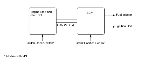
Early Stage Injection Control
-
Early stage injection control shortens the time it takes the engine to restart after the stop and start system stops the engine, thus allowing smooth initial acceleration.
-
The ECM memorizes the crankshaft angle detected by the crank position sensor when the engine is stopped by the stop and start system.
-
The ECM judges the injection required and decides which cylinder to ignite when the driver does restart operation. The ECM then uses this information as it starts the engine.
-
-
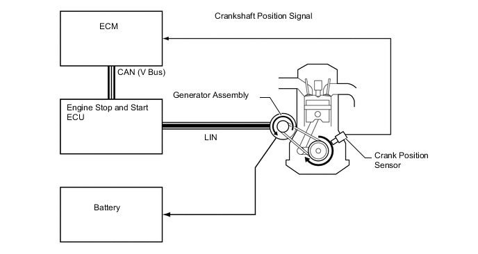
Stopping Position Control*
-
While the engine stopping operation is performed, the ECM uses ignition timing and alternator load torque to control the crankshaft position so that it is at the optimal position for engine start.
-
The ECM calculates the amount of electricity that needs to be generated to produce the load torque necessary for controlling and sends requests for electricity generation to the alternator via the stop and start ECU. The ECM inputs the applied crankshaft angle signal and performs feedback.
Tech Tips
*: Models with M/T
-
-
Hill-start Assist Function
-
The driving force (creep phenomenon) of a former CVT vehicle is regulated by depressing the brake pedal while stopping, and the driving force is transmitted by releasing the brake pedal when starting the vehicle. However, when starting a stop and start system equipped vehicle with its engine stopped due to the activation of the idle stop function, there is a short time delay of the driving force to be generated as the engine will start after the brake pedal is released.
-
The hill-start assist function is a system to assist starting of a stop and start system equipped vehicle on a slope to deal with the reason described above, retaining the brake hydraulic pressure until the driving force is generated, and releasing the brake hydraulic pressure automatically after the driving force is generated.
-
-
Tandem Solenoid Starter Control*
-
Tandem solenoid starter (starter assembly) equips with a pinion push out solenoid (SL1) and a motor drive solenoid (SL2) separately so that the pinion can engage with the ring gear even if the engine is rotating by its inertia before fully stopping.
-
If there is an engine start request while the engine is rotating by its inertia before fully stopping, the engine stop and start ECU drives the pinion push out solenoid (SL1) by determining the timing to push out the pinion to engage with the ring gear in accordance with the state of reduction of the engine rotation. After the pinion and the ring gear engages and a certain period of time passes, the motor drive solenoid (SL2) is driven to crank the engine.
-
ICR (Inrush Current Reduction) has been provided for the purpose to stabilize the vehicle's power supply voltage by suppressing a large current (rush current) to be flew temporarily at the time when initiating the starter motor.
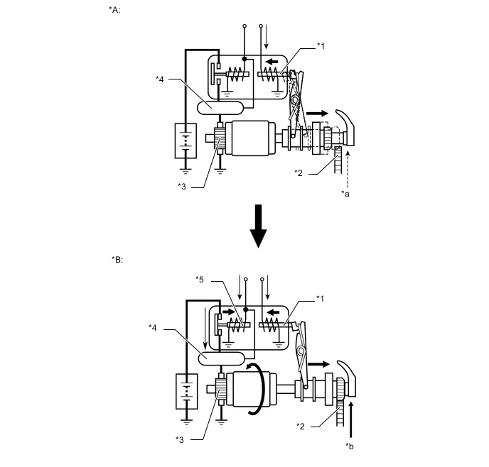
Text in Illustration *A Operation of Pinion *B Operation of Motor *1 Pinion Push Out Solenoid (SL1) *2 Ring Gear Sub-assembly *3 Starter Motor *4 ICR Relay *5 Motor Drive Solenoid (SL2) - - *a Rotating Engine *b Cranking Tech Tips
*: Models with 1NZ-FE Engine
-
-
System Prohibit Control
-
For safety, battery protection, comfort and ECU learning reasons, the engine stop and start ECU prohibits stop and start system operation if any one of the following conditions is met.
System Prohibit Control (1NR-FE Engine) Prohibition Reason Condition Safety If the engine is started with the hood open, such as when jump starting, engine restart operation cannot be ensured. Therefore, stop and start system operation will be prohibited. The operation of the system will be restored for the next trip. If the driver door or hood is opened before the engine stops, stop and start system operation will be prohibited for safety reasons. The brake booster vacuum is insufficient. If the air conditioning is on when the outside temperature is low, stop and start system operation will be prohibited. If the engine stop and start ECU receives an airbag deployment signal in the event of a collision, stop and start system operation will be prohibited for safety reasons. If the driver seat belt is released before the engine stops. Battery Protection If the electrical load is high and the engine is stopped for a long period of time, stop and start system operation will be prohibited. A refresh charge is performed every time the vehicle is driven for a total of 20 hours. During the refresh charge, which takes 30 minutes to 1 hour, stop and start system operation will be prohibited. If the percentage of the idling stop period (idling stop operating ratio) against the IG ON period exceeds a certain amount, the stop and start system operation will be prohibited.
-
If the battery integrated current is less than 0 A-sec after engine start by ignition switch operation, the stop and start system operation will be prohibited.
-
After the integrated current value increases to 0 A-sec or more once:
-
-3564 A-sec*1 (-3110 A-sec*2) or less: When the battery temperature is 10°C(50°F) or more, stop and start system operation will be prohibited.
-
-990 A-sec*1 (-864 A-sec*2) or less: When the battery temperature is less than 10°C(50°F), stop and start system operation will be prohibited.
Comfort If the air conditioning is on when the outside temperature is high and the evaporator temperature is high, stop and start system operation will be prohibited. If the heater is on when the outside temperature is low and the engine coolant temperature is low, stop and start system operation will be prohibited. If the front DEF switch and blower switch are on, stop and start system operation will be prohibited (Models with air conditioning system). If the outside temperature is below -5°C (23°F). If the blower switch is turned on while the outside temperature is low, the stop and start system operation will be prohibited for a certain period after engine start. If both the A/C switch and the blower switch are turned on, the stop and start system operation will be prohibited for a certain period after engine start. ECM Learning ECM learning is not complete. Tech Tips
*1: Models with CVT
*2: Models with M/T
System Prohibit Control (1NZ-FE Engine) Prohibition Reason Condition Safety If the engine is started with the hood open, such as when jump starting, engine restart operation cannot be ensured. Therefore, stop and start system operation will be prohibited. The operation of the system will be restored for the next trip. If the driver door or hood is opened before the engine stops, stop and start system operation will be prohibited for safety reasons.*1 The brake booster vacuum is insufficient. If the air conditioning is on when the outside temperature is low, stop and start system operation will be prohibited. If the engine stop and start ECU receives an airbag deployment signal in the event of a collision, stop and start system operation will be prohibited for safety reasons. If the driver seat belt is released before the engine stops. Battery Protection During charging for refresh.
(30 minutes to 1 hour per approximately 20 operating hours)
When the idling stop ratio reaches the specified value or more. The battery voltage has been dropped. (The integrated current value *2 is below the threshold.) Comfort If the air conditioning is on when the outside temperature is high and the evaporator temperature is high, stop and start system operation will be prohibited. If the heater is on when the outside temperature is low and the engine coolant temperature is low, stop and start system operation will be prohibited. If the front DEF switch and blower switch are on, stop and start system operation will be prohibited (Models with air conditioning system). If the outside temperature is below -5°C (23°F). If the blower switch is turned on while the outside temperature is low, the stop and start system operation will be prohibited for a certain period after engine start. If both the A/C switch and the blower switch are turned on, the stop and start system operation will be prohibited for a certain period after engine start. ECM Learning ECM learning is not complete.*3 Operability While the steering wheel is turning (a rotation speed of 45° per second or more), the stop and start system is prohibited to operate. Tech Tips
*1: Even if the engine food is opened while the idling stop control is active, the engine starts if the shift lever is in the P or N position. However, the engine does not start if the shift lever is in the D position. In this case, start the engine with the normal starting operation after moving the shift lever in the P or N position.
*2: Regarding Battery Integrated Current
In the stop and start system, the engine stop and start ECU switches the system control mode (stop and start system control permitted/prohibited) based on the battery condition (charge/discharge condition) to protect the battery and to ensure stable engine restarting performance.
The battery charge-discharge condition is determined from the integrated current value calculated from the battery current sensor signal. The integrated current value is obtained by multiplying the current (ampere) detected from the battery current sensor assembly by the time (seconds), and it is expressed in the unit A-sec. This can be measured by Global TechStream (GTS).
The engine stop and start ECU determines the power charge based on the integrated current value, and it prohibits stop and start system control if the value is below the threshold, because the battery might not be able to start the engine. The threshold values according to the battery temperature and battery charge condition.
*3: If the ECM has been replaced or the ECM's learning value is cleared by using a diagnosis tool, the stop and start system operation will be prohibited after the ECM's ISC flow rate learning is completed.
-
-
-
Warning Control
-
The driver will be warned if any of the following operations are performed.
Operation Warning Control The driver seat belt is released. The engine starts. Driver door is opened. (Shift Position P, N) Driver door is opened. (Shift Position D) Buzzer sounds, the stop and start indicator light blinks, and the engine starts. Hood is opened. (Shift Position P, N)*1 The engine starts. Hood is opened. (Shift Position D)*1 Engine restarting is stopped. Shift lever is moved without depressing the brake pedal. *2 Buzzer sounds. Shift lever is moved without depressing the clutch pedal. *3 Buzzer sounds. Tech Tips
*1: Even if the engine food is opened while the idling stop control is active, the engine starts if the shift lever is in the P or N position. However, the engine does not start if the shift lever is in the D position. In this case, start the engine with the normal starting operation after moving the shift lever in the P or N position.
*2: Models with CVT
*3: Models with M/T
-
-
-
CONSTRUCTION
-
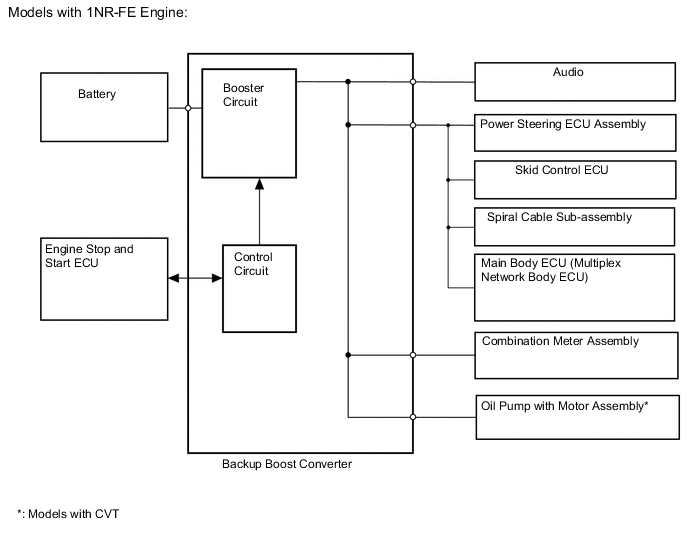
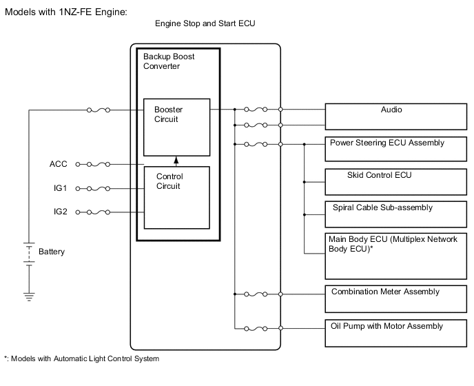
Backup Boost Converter
-
The backup boost converter uses a semiconductor relay. The semiconductor relay also functions as a fuse. When overcurrent is detected, the relay is turned off to protect the circuit.
-
The backup boost converter supplies battery voltage to help make up for the voltage drop that occurs when the engine is restarted. This prevents the operation of the following equipment from being interrupted due to low battery voltage.
-
Audio
-
Spiral Cable Sub-assembly
-
Main Body ECU (Multiplex Network Body ECU)
-
Power Steering ECU Assembly
-
Skid Control ECU
-
Combination Meter Assembly
-
Oil Pump with Motor Assembly
-
-
-
Permanently Engaged Gear Mechanism*
-
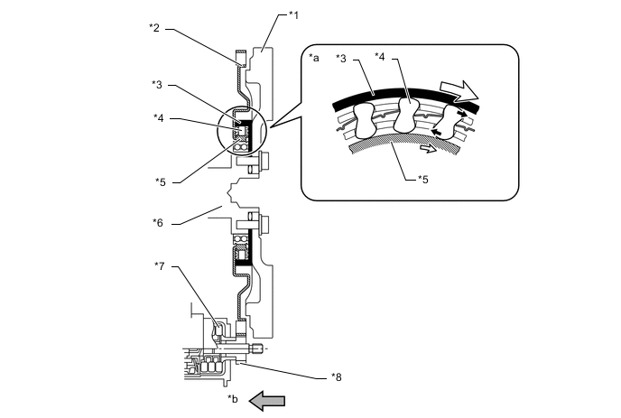
In this permanently engaged gear mechanism, the bearing, one-way clutch, and ring gear are positioned between the crankshaft and the flywheel or drive plate and ring gear sub-assembly, allowing the pinion gear of the starter and the ring gear to be continuously engaged.
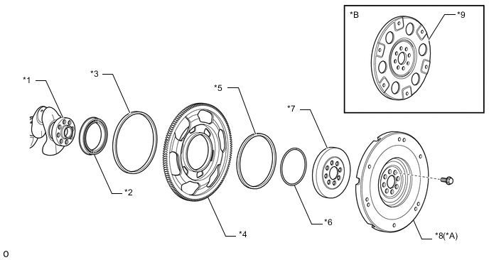
Text in Illustration *A Models with M/T *B Models with CVT *1 Crankshaft *2 Crankshaft Bearing *3 Rear Engine Oil Seal *4 Ring Gear Sub-assembly *5 Inner Oil Seal *6 Ring Gear Snap Ring *7 One-way Clutch Assembly *8 Flywheel Sub-assembly *9 Drive Plate and Ring Gear Sub-assembly - - -
When the engine is being started or restarted, the starter starts operating and the ring gear sub-assembly rotates. Then, the inner race of the ring gear sub-assembly pushes the sprags against the outer race, locking the ring gear sub-assembly to the crankshaft, thus turning the crankshaft and starting the engine.
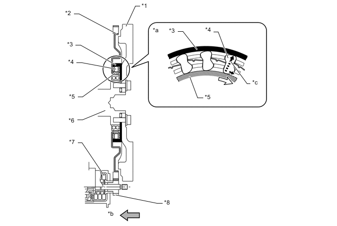
Text in Illustration (Models with M/T:) *1 Flywheel Sub-assembly *2 Ring Gear Sub-assembly *3 Outer Race (One-way Clutch Assembly) *4 Sprag *5 Inner Race (Ring Gear Sub-assembly) *6 Crankshaft *7 Starter Assembly *8 Pinion Gear *a Front-view *b Engine Front *c Torque Transmission - - 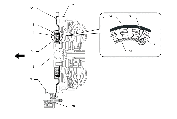
Text in Illustration (Models with CVT:) *1 Drive Plate and Ring Gear Sub-assembly *2 Ring Gear Sub-assembly *3 Outer Race (One-way Clutch Assembly) *4 Sprag *5 Inner Race (Ring Gear Sub-assembly) *6 Crankshaft *7 Starter Assembly *8 Pinion Gear *a Front-view *b Torque Transmission 
Engine Front - - -
After the engine has started, the crankshaft starts turning faster than the ring gear sub-assembly. When this happens, the sprags of the one-way clutch are released and the ring gear sub-assembly and the crankshaft are unlocked. If the starter stops, the ring gear sub-assembly also stops.
Text in Illustration (Models with M/T:) *1 Flywheel Sub-assembly *2 Ring Gear Sub-assembly *3 Outer Race (One-way Clutch Assembly) *4 Sprag *5 Inner Race (Ring Gear Sub-assembly) *6 Crankshaft *7 Starter Assembly *8 Pinion Gear *a Front-view *b Engine Front 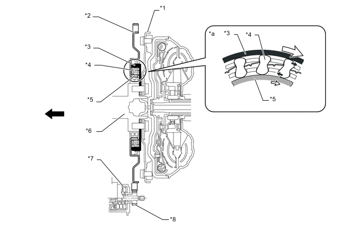
Text in Illustration (Models with CVT:) *1 Drive Plate and Ring Gear Sub-assembly *2 Ring Gear Sub-assembly *3 Outer Race (One-way Clutch Assembly) *4 Sprag *5 Inner Race (Ring Gear Sub-assembly) *6 Crankshaft *7 Starter Assembly *8 Pinion Gear *a Front-view - - Engine Front - - Tech Tips
*: Models with 1NR-FE Engine
-
-
-
OPERATION
-
Combination Meter Assembly
-
The combination meter receives the idling on/off signals from the engine stop and start ECU.
-
Press the ODO/TRIP DISPLAY switch several times to change the multi-information display and display the idle stop time.
-
Eco Odo Display: Total idle stop time since the last time the reset was mode. The reset can be performed by pressing and holding the ODO/TRIP DISPLAY switch (not erased by turning ignition (engine) switch off).
-
-
System operation status and warnings are known to the driver by the stop and start indicator light, stop and start cancel indicator light and buzzer.
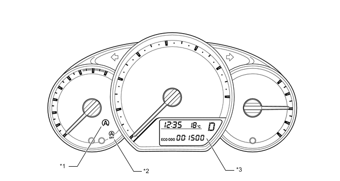
Text in Illustration *1 Stop and Start Indicator Light *2 Stop and Start Cancel Indicator Light *3 Multi-information Display - - Stop and Start Indicator Light Operation (M/T Models with 1NR-FE Engine) Item Condition Stop and Start Indicator Light Buzzer System Operating (Engine is stopped) The vehicle is operating normally. Illuminates Does not sound The shift lever is operated without depressing the clutch pedal. Sounds The driver's door is opened. Stop and Start Indicator Light Operation (CVT Models with 1NR-FE Engine) Item Condition Stop and Start Indicator Light Buzzer System Operating (Engine is stopped) The vehicle is operating normally. Illuminates Does not sound The shift lever is operated without depressing the brake pedal. Blinks* Sounds When the shift lever is in D, the driver's seat belt is unfastened and the driver's door is opened. Tech Tips
*: The blinking interval is 0.13 seconds.
Stop and Start Indicator Light Operation (Models with 1NZ-FE Engine) Item Condition Stop and Start Indicator Light Buzzer System Operating (Engine is stopped) The vehicle is operating normally. Illuminates Does not sound When the shift lever is in D, the driver's seat belt is unfastened and the driver's door is opened. Blinks* Sounds Tech Tips
*: The blinking interval is 0.15 seconds.
Stop and Start Cancel Indicator Light Operation Condition Stop and Start Cancel Indicator Light The vehicle is stopped and system operation conditions are met. OFF While the stop and start system prevents the engine stop control from operating. Illuminates When the stop and start system cancel switch assembly is ON. Any Diagnostic Trouble Code (DTCs) are detected. Blinks* The number of times the starter has been operated exceeds the threshold. Tech Tips
*: The blinking interval is 0.5 seconds.
-
-
-
DIAGNOSIS
-
When the engine stop and start ECU detects a malfunction and CAN communication is normal, the engine stop and start ECU records information related to the fault. Furthermore, the stop and start cancel indicator light in the combination meter assembly blinks to inform the driver that all CAN communication are normal.
-
The engine stop and start ECU will also store the Diagnostic Trouble Code (DTC) of the malfunctions. The DTC can be read using the Global TechStream (GTS).
-