ENGINE UNIT
-
CONSTRUCTION
-
Cylinder Head Cover Sub-assembly
-
A magnesium-alloy cylinder head cover sub-assembly is used to achieve significant weight reduction. By optimizing the shape, rib positions, and other factors, sufficient quietness has been ensured.
-
An oil delivery pipe is installed inside the cylinder head cover sub-assembly. This ensures lubrication of the sliding parts of the No.1 valve rocker arm sub-assembies, improving reliability.
-
By optimizing the blow-by gas intake position and fresh air intake positions, the ventilation efficiency has been improved.
-
By providing ventilation baffle plates in the cylinder head cover sub-assembly, the amount of the oil taken away in the blow-by gas has been reduced to achieve reduced oil consumption and cleaner exhaust gas. In addition, a two-step type baffle plate is provided in the vacuum-side PCV chamber to prevent the engine oil splashed by the camshafts from being sucked into the blow-by gas intake port.
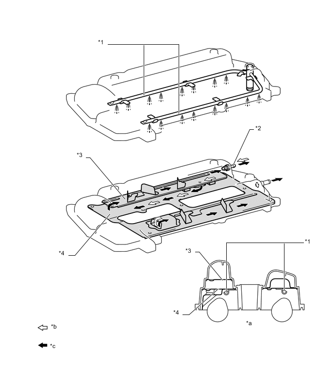
Text in Illustration *1 Cylinder Head Oil Nozzle *2 PCV Valve *3 No.1 Baffle Plate *4 No.2 Baffle Plate *a Cylinder Head Cover Sub-assembly Cross Section *b Fresh Air *c Blow-by Gas - -
-
-
Cylinder Head Sub-assembly
-
The cylinder head sub-assembly structure has been simplified by separating the camshaft housing (cam journal portion) from the cylinder head sub-assembly.
-
The angle of the intake and exhaust valves has been narrowed and set at 21.5° to permit a compact cylinder head sub-assembly.
-
A taper squish combustion chamber is used to improve anti-knocking performance and intake efficiency. In addition, engine performance and fuel economy have been improved.
-
In the cylinder head sub-assy, the diameter of the intake ports is reduced and a multi-step cross-sectional shape is adopted in the intake valve seats to realize smoother intake air flow. As a result, enough intake air flow is secured while further strengthening the tumble flow so that the compatibility between fuel economy and engine output is secured. According to the improved combustion efficiency due to the strengthened tumble flow, even more EGR gas can be introduced, enabling further low fuel consumption and emission.
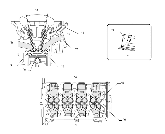
Text in Illustration *1 Fuel Injector Assembly *2 Intake Port *3 21.5° *4 Taper Squish *5 Spark Plug *6 EGR Gas Passage *7 Intake Valve Seat - - *a Intake Side *b Exhaust Side *c Multi-step Cross-sectional Shape - -
-
-
Cylinder Block Sub-assembly
-
An aluminum cylinder block sub-assembly with a 8 mm (0.31 in.) distance between the cylinder bores is used to achieve a compact and lightweight configuration.
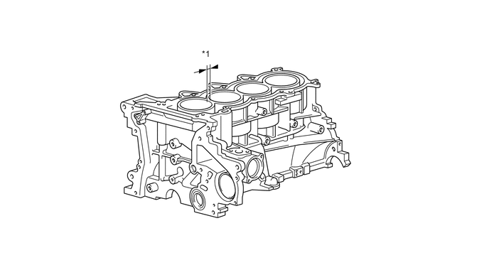
Text in Illustration *1 8 mm (0.31 in.) - - -
Through the use of an offset crankshaft, the centerline of the cylinder bores is shifted 12 mm (0.47 in.) towards the exhaust in relation to the centerline of the crankshaft. Thus, the side force (thrust) applied to the cylinder walls is reduced when maximum combustion pressure is applied. This contributes to fuel economy.
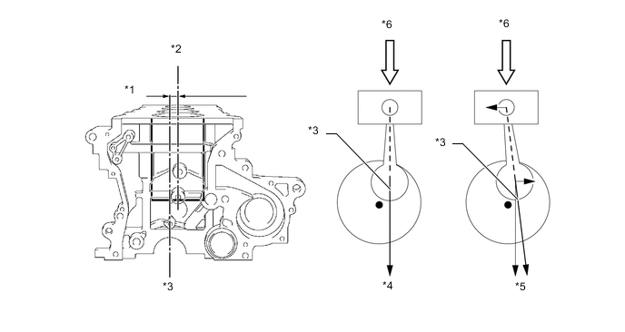
Text in Illustration *1 12mm (0.47 in.) *2 Bore Centerline *3 Crankshaft Centerline *4 Offset Crankshaft *5 Non-offset Crankshaft *6 Maximum Pressure
-
-
Oil Pan
-
The oil pan sub-assembly is made of aluminum die-cast.
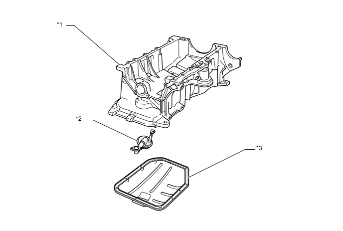
Text in Illustration *1 Oil Pan Sub-assembly *2 Oil Strainer *3 No.2 Oil Pan Sub-assembly - -
-
-
Piston
-
The pistons are made of aluminum alloy to allow them to be compact and lightweight.
-
The piston head portion uses a taper squish shape to achieve improved fuel combustion efficiency.
-
Semi floating type piston pins are used.
-
Narrow-width piston rings are used to reduce weight and friction.
-
The piston skirt is coated with resin to reduce friction losses.
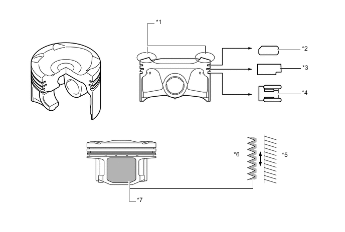
Text in Illustration *1 Taper Squish Shape *2 No.1 Compression Ring *3 No.2 Compression Ring *4 Oil Ring *5 Cylinder Bore *6 Piston *7 Resin Coating - -
-
-
Connecting Rod Sub-assembly and Connecting Rod Bearing
-
The connecting rod sub-assemblies are made of high-strength steel for weight reduction.
-
Plastic region tightening bolts are used to achieve a light weight.
-
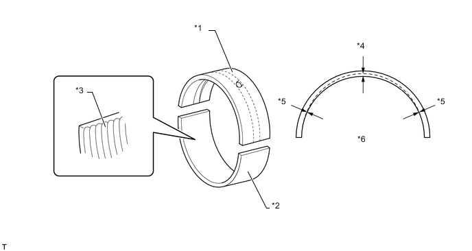
The width of the connecting rod bearings has been optimized to reduce friction.
-
The lining surface of the connecting rod bearing is micro-grooved to provide an optimal oil clearance. As a result, cold-engine cranking performance has been improved and engine vibration has been reduced.
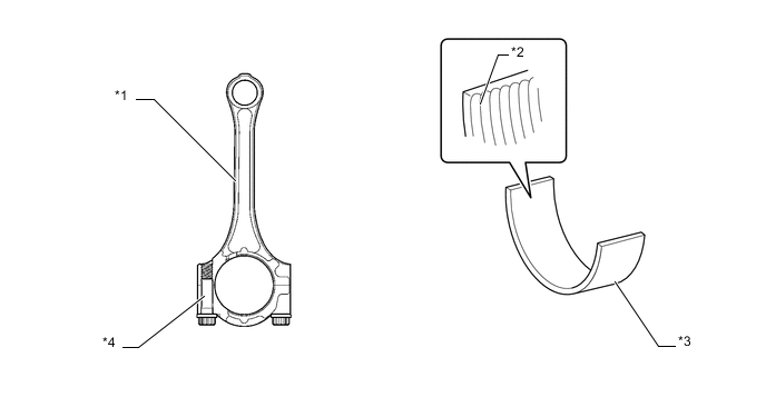
Text in Illustration *1 Connecting Rod Sub-assembly *2 Micro-grooved *3 Connecting Rod Bearing *4 Plastic Region Tightening Bolt
-
-
Crankshaft and Crankshaft Bearing
-
The crankshaft has 5 main journals and 4 balance weights.
-
The diameter and width of the pins and journals have been reduced, and the pins for the No.1 and No.4 cylinders have been made highly rigid to realize a lightweight and low-friction performance.
-
A crank position sensor rotor is pressed into the crankshaft to realize an integrated configuration.
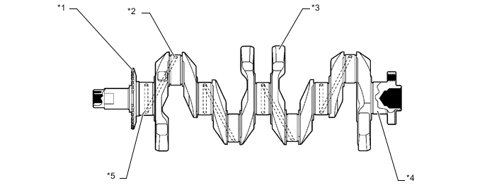
Text in Illustration *1 Crank Position Sensor Rotor *2 Oil Hole *3 Balance Weight *4 No. 5 Journal *5 No. 1 Journal - - -
The width of the crankshaft bearings has been optimized to reduce friction.
-
The lining surface of the crankshaft bearing is micro-grooved to provide an optimal oil clearance. As a result, cold-engine cranking performance has been improved and engine vibration has been reduced.
-
An oil groove is provided on each upper main bearing (crankshaft bearing). The oil groove is deep at the center and is shallow at the edges to reduce the amount of oil that will leak from the crankshaft bearing. As a result, the size of the oil pump has been reduced, thus minimizing friction.
Text in Illustration *1 Upper Main Bearing (Crankshaft Bearing) *2 Lower Main Bearing (Crankshaft Bearing) *3 Micro-grooved *4 Center *5 Edge *6 Oil Groove Depth
-
-
Valve Mechanism
-
Intake and exhaust efficiency has been increased due to the larger total port areas.
-
The valve mechanism uses a No.1 valve rocker arm sub-assembly with built-in needle bearings. This reduces the friction that occurs between the cams and the areas on the No.1 valve rocker arm sub-assemblies that push the valves down, thus improving fuel economy.
-
Hydraulic lash adjusters, which maintain a constant zero valve clearance through the use of oil pressure and spring force, are used.
-
The camshaft and No.2 camshaft are driven by a chain sub-assembly.
-
This engine uses the Variable Valve Timing-intelligent (VVT-i) system which controls the camshaft to provide optimal valve timing according to driving conditions. With this, lower fuel consumption, higher engine performance, and exhaust emission have been reduced.
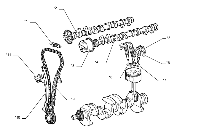
Text in Illustration *1 No. 2 Chain Vibration Damper *2 No.2 Camshaft *3 Camshaft Timing Gear Assembly *4 Camshaft *5 No.1 Valve Rocker Arm Sub-assembly *6 Hydraulic Lash Adjuster *7 Intake Valve *8 Exhaust Valve *9 No. 1 Chain Vibration Damper *10 Chain Tensioner Slipper *11 No.1 Chain Tensioner Assembly - -
-
-
Camshaft
-
Oil passages are provided in the camshaft in order to supply engine oil to the VVT-i system.
-
A Camshaft Timing Gear Assembly has been installed on the front of camshaft to vary the timing of the intake valves.
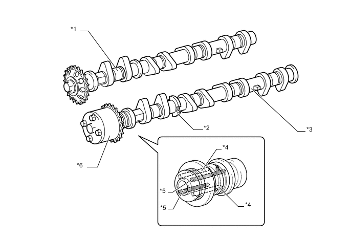
Text in Illustration *1 No.2 Camshaft *2 Timing Rotor *3 Camshaft *4 Oil Passage (Retard) *5 Oil Passage (Advance) *6 Camshaft Timing Gear Assembly
-
-
Camshaft Timing Gear Assembly
-
The camshaft timing gear assembly consists of a housing driven from the chain sub-assembly and a vane coupled with the camshaft.
-
The camshaft timing gear assembly have a 4-blade vane.
-
The oil pressure sent from the advanced or retarded side path at the camshaft causes rotation in a camshaft timing gear assembly vane circumferential direction to vary the intake valve timing continuously.
-
When the engine is stopped, a lock pin locks the camshaft at its most retarded position, to ensure that the engine starts properly.
-
An advance assist spring is provided on the exhaust side camshaft timing gear assembly. This spring applies torque in the advance direction when the engine is stopped, thus ensuring the engagement of the lock pin.
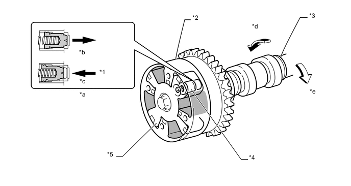
Text in Illustration *1 Oil Pressure *2 Housing *3 Camshaft *4 Lock Pin *5 Vane - - *a Lock Pin Operation *b Engine Stopped *c Engine Operating *d Retard *e Advance - -
-
-
Hydraulic Lash Adjuster
-
A hydraulic lash adjuster is located at the fulcrum of each No.1 valve rocker arm sub-assembly. A hydraulic lash adjuster consists primarily of a plunger, a plunger spring, a check ball, and a check ball spring.
-
The hydraulic lash adjuster is actuated by the engine oil, plunger spring, and check ball spring. The oil pressure and the spring force that act on the plunger push the No.1 valve rocker arm sub-assembly against the cam, in order to adjust the valve clearance. This reduces the engine noise that is created during the opening and closing of the valve.
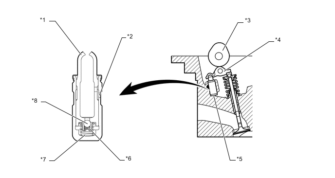
Text in Illustration *1 Plunger *2 Oil Passage *3 Cam *4 No.1 Valve Rocker Arm Sub-assembly *5 Hydraulic Lash Adjuster *6 Check Ball Spring *7 Plunger Spring *8 Check Ball Tech Tips
Valve clearance adjustment is not necessary because hydraulic lash adjusters are used.
-
-
Chain Sub-assembly and No.1 Chain Tensioner Assembly
-
A chain sub-assembly with an 8 mm (0.31 in.) pitch is used to make the engine more compact.
-
The contacting surface area between the chain sub-assembly and chain guide is reduced to lower friction.
-
The No.1 chain tensioner assembly uses a spring and oil pressure to maintain proper chain tension at all times.
-
The No.1 chain tensioner assembly suppresses noise generated by the chain sub-assembly.
-
The No.1 chain tensioner assembly is a ratchet type tensioner with a non-return mechanism.
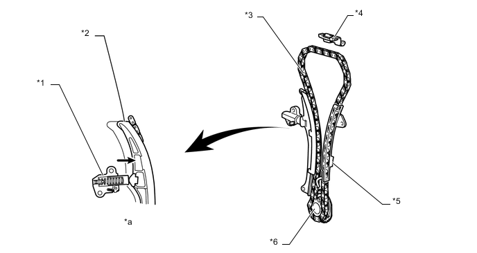
Text in Illustration *1 No.1 Chain Tensioner Assembly *2 Chain Tensioner Slipper *3 Chain Sub-assembly *4 No. 2 Chain Vibration Damper *5 No. 1 Chain Vibration Damper *6 Crankshaft Timing Sprocket *a No.1 Chain Tensioner Assembly Operation - -
-
-
Timing Chain Cover Assembly
-
An aluminum die-cast timing chain cover is used.
-
The timing chain cover has an integrated construction including parts of the cooling system (water pump and water passage) and the lubrication system (oil pump and oil passage). Thus, the number of parts has been reduced for weight reduction.
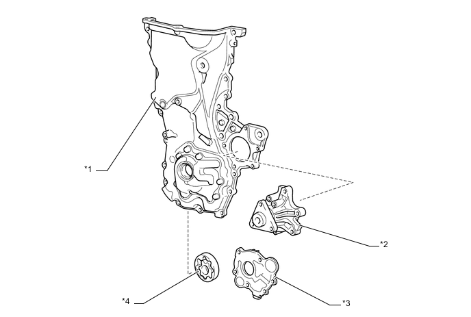
Text in Illustration *1 Timing Chain Cover Assembly *2 Engine Water Pump Assembly *3 Oil Pump Housing *4 Oil Pump Rotor
-
-
V-ribbed Belt
-
Accessory components are driven by a serpentine belt consisting of a single V-ribbed belt. This reduces the overall engine length, weight and the number of engine parts.
-
The automatic tensioner eliminates the need for tension adjustment.
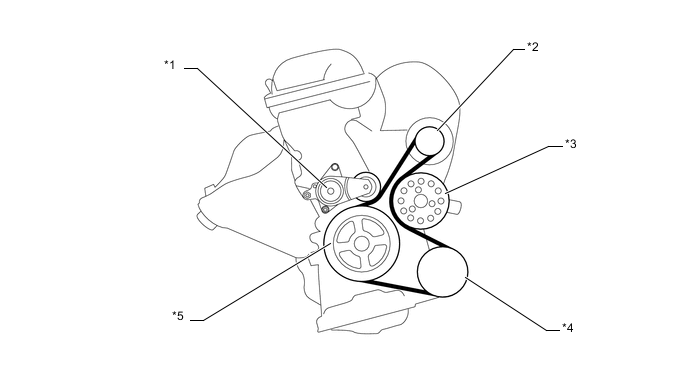
Text in Illustration *1 V-ribbed Belt Tensioner Assembly *2 Generator Pulley *3 Water Pump Pulley *4 Cooler Compressor Pulley *5 Crankshaft Pulley - -
-
-