СИСТЕМА АВТОМАТИЧЕСКОЙ ТРАНСМИССИИ
-
CONSTRUCTION
-
The shift solenoid valve DSL (S1) and shift solenoid valve S4 (SR) are 3-way solenoid valves.
-
The No. 3 transmission solenoid assembly (S2) uses a 2-way solenoid valve.
-
A filter is provided at the tip of the solenoid valve to further improve operational reliability.
Figure 1. Shift Solenoid Valve S1
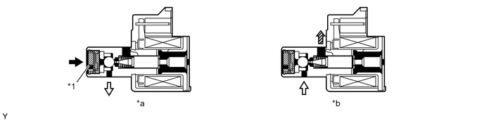
*1 Filter - - *a Off Condition *b On Condition 
Line Pressure 
Control Pressure 
Drain - - Figure 2. Shift Solenoid Valve S2
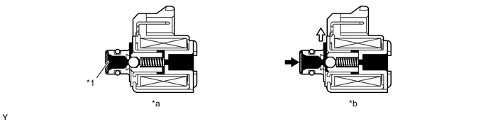
*1 Filter - - *a Off Condition *b On Condition Line Pressure Control Pressure Figure 3. Shift Solenoid Valve SR
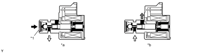
*1 Filter - - *a Off Condition *b On Condition Line Pressure Control Pressure Drain - - -
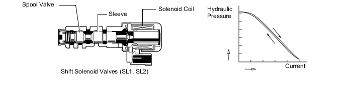
In order to provide a hydraulic pressure that is proportional to the current that flows to the solenoid coil, the shift solenoid valves SL1 and SL2 linearly control the clutch pressure based on the signals from the ECM.
-
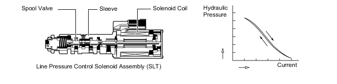
In order to provide a hydraulic pressure that is proportional to the current that flows to the solenoid coil, the line pressure control solenoid assembly (SLT) linearly controls the line pressure based on the signals from the ECM.
-
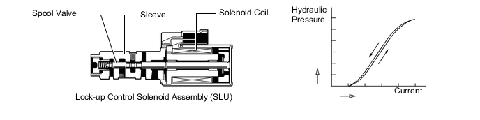
In order to provide a hydraulic pressure that is proportional to the current that flows to the solenoid coil, the lock-up control solenoid assembly (SLU) linearly controls the lock-up clutch engagement pressure based on the signals from the ECM.
Function of Shift Solenoid Valves Shift Solenoid Valve Function S1 Switches the 2-3 shift valve. S2 Switches the 1-2 shift valve and the 3-4 shift valve. SR Switches the clutch apply control valve. SL1
-
C1clutch pressure control
-
Accumulator back pressure control
SL2 B1, B2and B4brake pressure control
SLT
-
Line pressure control
-
Accumulator back pressure control
SLU
-
Lock-up clutch pressure control
-
Accumulator back pressure control
-
-