LIGHTING SYSTEM
-
FUNCTION OF MAIN COMPONENTS
Component Function Headlight Dimmer Switch Assembly Light Control Switch The light control switch transmits a switch position signal to the main body ECU (driver side junction block assembly). Main Body ECU (Driver Side Junction Block Assembly) The main body ECU (driver side junction block assembly) receives the head position signal from the light control switch and transmits a signal to the LED driver module (light control ECU). Headlight Unit Light Emitting Diode (LED) The LED light shines further ahead over a broader area, increasing the area visible to the driver. LED Driver Module (Light Control ECU) The LED driver module keeps a constant level of direct current applied to the LED, achieving stable LED illumination. Combination Meter Assembly Multi-information Display The multi-information display displays a warning message to inform the driver when the LED driver module detects a malfunction in the LED headlight system. Master Warning Light The master warning light illuminates to inform the driver when the LED driver module detects malfunctions in the LED headlight system. -
FUNCTION
-
The Light Emitting Diode (LED) headlight system consists of LEDs and an LED driver module.
-
A fail-safe function is provided.
-
-
SYSTEM CONTROL
-
LED Driver Module (Light Control ECU)
-
When the headlights are turned on, the LED driver modules immediately turn on the LEDs (approximately 0.1 seconds). In addition, by regulating the output current flowing into the LEDs at a specified level, the LED driver modules prevent the light from getting brighter and dimmer due to voltage variation.
-
If malfunctions occur in the LED headlight system, the LED driver module transmits fail signals to the main body ECU (driver side junction block assembly). When the main body ECU receives the fail signals, it transmits signals to the combination meter assembly to warn the driver.
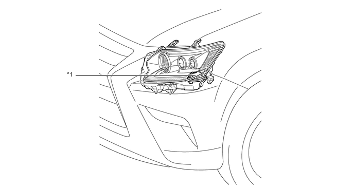
*1 LED Driver Module (Light Control ECU) - -
-
-
Combination Meter
-
If malfunctions occur in the LED headlight system, the combination meter assembly warns the driver by indicating a message on the multi-information display, sounding the buzzer and illuminating the master warning light when receiving signals from the main body ECU.
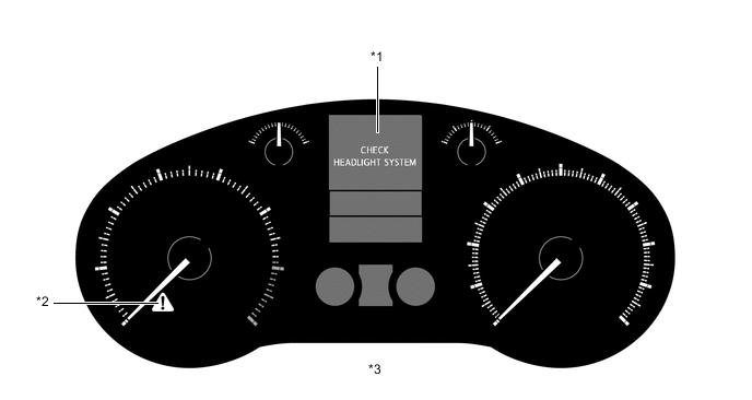
*1 Multi-information Display *2 Master Warning Light *3 Combination Meter Assembly - -
-
-
-
FAIL-SAFE
-
The LED driver module executes the fail-safe actions listed below in accordance with the problem that has been detected:
Problem Outline Detection of Abnormal Input Voltage When the voltage that is input to the LED driver module deviates from the normal operating voltage (10 V to 16 V), the LED driver module stops illuminating the headlights. The LED driver module resumes illuminating the headlights once the voltage reverts to the normal operating voltage. However, if the input voltage decreases after the headlights have illuminated, the headlights remain illuminated until the input voltage becomes insufficient to light the LEDs. Detection of Abnormal Output (Open Circuit or Short Circuit) If an abnormal condition (open or short) occurs in the voltage that is output by LED driver module, the LED driver module stops operation and maintains this state until the power is reinstated. Power is reinstated by turning the light control switch from off to on.
-