AIR CONDITIONING SYSTEM
-
CONSTRUCTION
-
The 10SR19 cooler compressor assembly features a compact, lightweight and low-noise swash plate design*1, and the 10S17 cooler compressor assembly features a compact, lightweight and low-noise 10-cylinder swash plate design*2.
-
*1: Except model for China
-
*2: Models for China
-
-
The cooler compressor assembly consists of an air conditioning pulley, shaft, lug plate, swash plate, piston, shoe, crank chamber, cylinder and lock sensor.
-
The lock sensor sends a cooler compressor assembly speed signal to the air conditioning amplifier assembly. The air conditioning amplifier assembly compares this signal with an engine speed signal sent from the crankshaft position sensor. If the air conditioning amplifier assembly determines that the air conditioning pulley has locked, the air conditioning amplifier assembly turns the magnetic clutch off.
-
A rotary valve capable of directing suction refrigerant into the cylinder has been provided.

*A Except Model for China *B Model for China -
In order to eliminate suction loss, the conventional suction valve has been replaced with a rotary valve.
-
A hollow shaft is used in the valve so as to allow refrigerant to be sucked into the compressing section of the cylinder through the hollow section. Holes individually arranged on the shaft and cylinder are designed to align during the rotation of the shaft. When the holes are aligned, refrigerant is sucked into the compressing section.
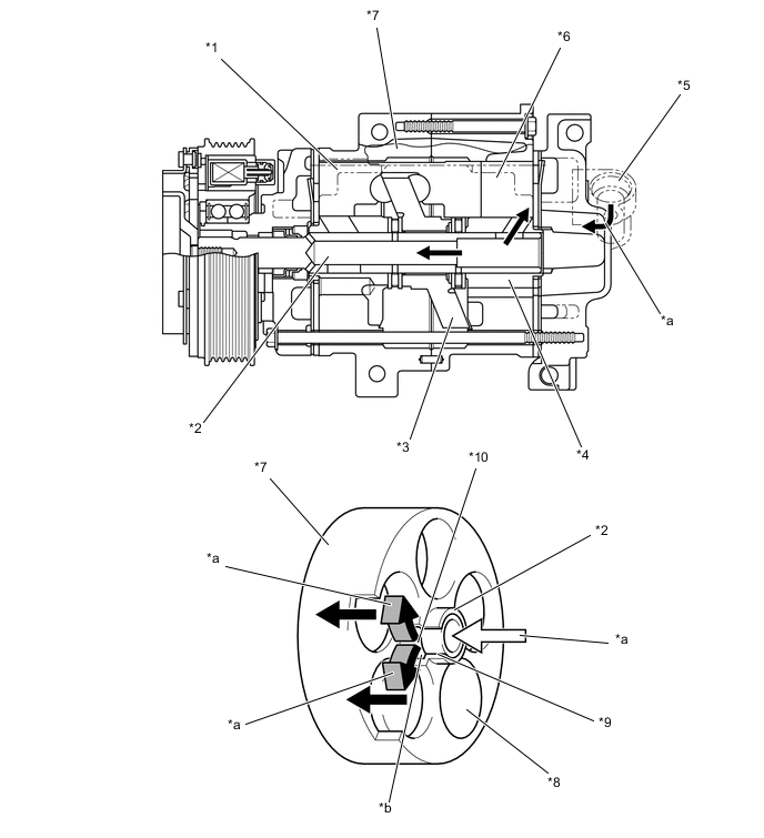
*1 Piston *2 Shaft *3 Lug Plate *4 Housing *5 Suction Section *6 Compressing Section *7 Cylinder *8 Cylinder Bore *9 Cylinder Suction Passage *10 Rotary Valve Suction Port *a Refrigerant Flow *b Position where Rotary Valve Suction Port and Cylinder Suction Passage Become Aligned
-