METER / GAUGE SYSTEM
-
CONSTRUCTION
-
An accessory meter assembly is used, which can show the cruise information display and air conditioning system display. The accessory meter assembly can also be used in the monitor system, wide view front and side monitor system or multi-terrain monitor system.
-
The display language will be the same as that set for the combination meter assembly.
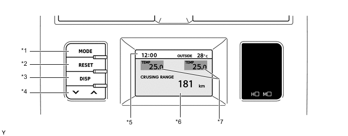
*1 MODE Switch *2 RESET Switch *3 DISP Switch *4 Up/Down Switch *5 Clock and Outside Temperature Display *6 Cruise Information Display or Air Conditioning System Display *7 Driver and Front Passenger Seats Set Temperature Display - - -
The accessory meter assembly has the following functions:
Function Outline Clock and Outside Temperature Display
-
Displays the clock.
-
Displays the outside temperature.
Driver and Front Passenger Seats Set Temperature Display Displays the air conditioning set temperature for the driver and front passenger seats. Cruise Information Display In the cruise information display, 5 types of information can be displayed:
-
Cruising Range
-
Average Fuel Consumption After Refueling and Current Fuel Consumption
-
Average Fuel Consumption
-
Average Vehicle Speed
-
Elapsed Time
Air Conditioning System Display Displays the status of the air conditioning system. Screen Adjustment Display The following adjustments can be made:
-
Contrast Adjustment
-
Brightness Adjustment
-
Switching Day Mode On/Off
Monitor System Display The image of each system is displayed. Wide View Front and Side Monitor System Display Multi-terrain Monitor System Display -
-
The display of the accessory meter assembly undergoes the following transitions:
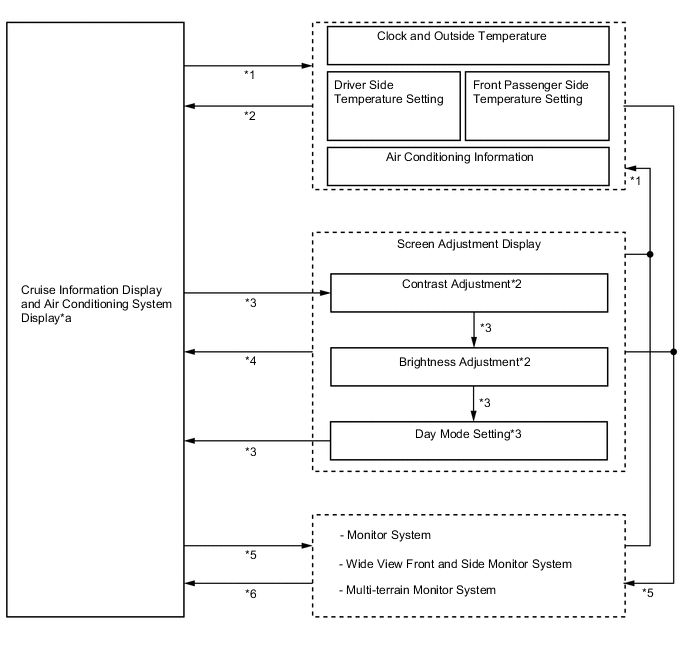
Text in Illustration *1 Air conditioning system is operated *2 Mode switch is pressed or no operation is performed for 6 seconds *3 DISP switch is pressed *4 No operation is performed for 10 seconds *5 Each system starts operating *6 Each system finishes operating *a See the following illustration for the display transitions of this component - - 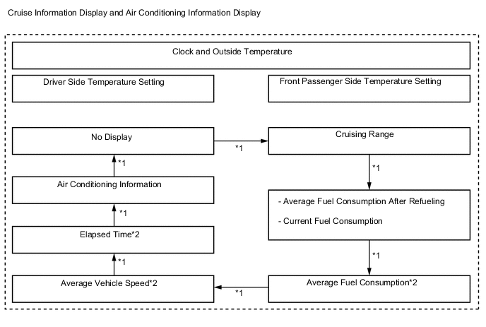
Text in Illustration *1 MODE switch is pressed *2 RESET switch is pressed and held (for 0.8 seconds or more) to reset the counter
-