LEXUS PARKING ASSIST-SENSOR SYSTEM
-
FUNCTION OF MAIN COMPONENTS
-
The components have the following functions:
Component Function Ultrasonic Sensors Detect the distance between the vehicle and the obstacle. Clearance Warning ECU Assembly*1 Judges the approximate distance between the vehicle and obstacle based on the signals from the ultrasonic sensors and sends the buzzer signal to the clearance warning buzzer. Parking Assist ECU*2
-
Judges the approximate distance between the vehicle and obstacle based on the signals from the ultrasonic sensors and sends the buzzer signal to the clearance warning buzzer.
-
Receives signals from switch operation and the ECU, and displays a clearance warning icon on the combination meter assembly and display and navigation module display.
Clearance Warning Buzzer Assembly Sounds intermittently to inform the driver that the clearance warning ECU assembly has detected an obstacle within the prescribed range. Multi-information Switch The LEXUS parking assist-sensor system can be turned on or off by operating this switch. Combination Meter Assembly
-
Transmits received vehicle speed signals to the clearance warning ECU assembly*1 or parking assist ECU*2.
-
Displays the detection location on the multi-information display when an obstacle is detected.
Display and Navigation Module Display*3 Displays the detection location on the display and navigation module display when an obstacle is detected. Accessory Meter Assembly*4 Displays the detection location on the accessory meter assembly when an obstacle is detected. Air Conditioning Amplifier Assembly Transmits the outside air temperature to the clearance warning ECU assembly*1 or parking assist ECU*2. Park/Neutral Position Switch Assembly Transmits the R position signal to the parking assist ECU*2 or clearance warning ECU assembly*1.
-
*1: Models without parking assist monitor system and wide view front and side monitor system
-
*2: Models with parking assist monitor system or wide view front and side monitor system
-
*3: Models with navigation system
-
*4: Models without navigation system
-
-
-
SYSTEM CONTROL
-
After the LEXUS parking assist-sensor system has started its activation, it sounds the clearance warning buzzer assembly for approximately 1 second, while checking for any malfunction in the ultrasonic sensors.
-
The on and off times of the clearance warning buzzer assembly vary as shown in the table below, depending on the distance between the obstacle and the ultrasonic sensor.
Front Ultrasonic Sensor - Obstacle Distance [mm (in.)] Off Time (ms) On Time (ms) Detection Area A B Ultrasonic Sensor Center Corners Detection Lever 1st Approx. 500 (19.7) to 1000 (39.4) - 650 150 2nd Approx. 375 (14.8) to 500 (19.7) Approx. 475 (18.7) to 600 (23.6) 150 150 3rd Approx. 300 (11.8) to 375 (14.8) Approx. 350 (13.8) to 475 (18.7) 75 75 4th Approx. 300 (11.8) or less Approx. 350 (13.8) or less 0 Continuous Rear Ultrasonic Sensor - Obstacle Distance [mm (in.)] Off Time (ms) On Time (ms) Detection Area C D Ultrasonic Sensor Center Corners Detection Lever 1st Approx. 650 (25.6) to 1500 (59.0) - 650 150 2nd Approx. 500 (19.7) to 650 (25.6) Approx. 375 (14.8) to 550 (21.7) 150 150 3rd Approx. 400 (15.7) to 500 (19.7) Approx. 250 (9.8) to 375 (14.8) 75 75 4th Approx. 350 (13.8) or less Approx. 250 (9.8) or less 0 Continuous 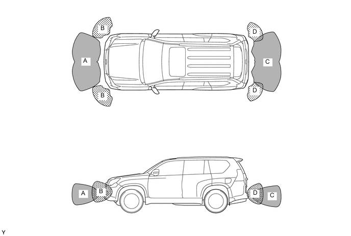
-
Operating Condition
-
The operating condition of each ultrasonic sensor differs in accordance with its installed position as shown in the table below:
Installation Position Operating Condition Front Corner
-
Engine switch is on (IG).
-
Clearance sonar main switch is on.
-
Shift lever is in anything except P.
-
Vehicle speed is approximately 10 km/h (6 mph) or less.
Front Center
-
Engine switch is on (IG).
-
Clearance sonar main switch is on.
-
Shift lever is in anything except P and R.
-
Vehicle speed is approximately 10 km/h (6 mph) or less.
Rear Center or Corner
-
Engine switch is on (IG).
-
Clearance sonar main switch is on.
-
Shift lever is in R.
-
-
-
-
DIAGNOSIS
-
If the system cannot activate its detection function due to a malfunction in an ultrasonic sensor, it alerts the driver of the malfunction by the sounding the clearance warning buzzer assembly. For details, refer to the Repair Manual.
-