BRAKE SYSTEM
-
CONSTRUCTION
-
The hydraulic brake booster consists of the master cylinder solenoid, brake booster with accumulator pump assembly and brake master cylinder reservoir assembly.
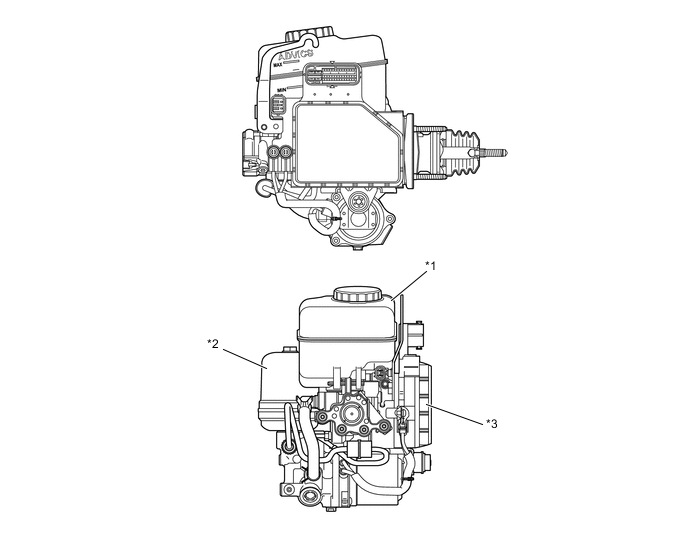
*1 Brake Master Cylinder Reservoir
- Reservoir
- Brake Fluid Level Warning Switch
*2 Brake Booster with Accumulator Pump Assembly
- Brake Booster Pump Assembly
- Brake Booster Accumulator Assembly
- Relief Valve
*3 Master Cylinder Solenoid
- Brake Master Cylinder
- Switching Solenoid Valve
- Control Solenoid Valve
- Accumulator Pressure Sensor
- Master Cylinder Pressure Sensor
- Control Pressure Sensor (Models with Pre-crash Safety System)
- Skid Control ECU
- - Figure 1. Hydraulic Circuit
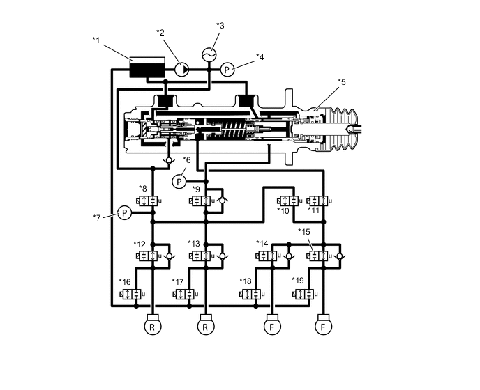
*1 Reservoir *2 Brake Booster Pump Assembly *3 Brake Booster Accumulator Assembly *4 Accumulator Pressure Sensor *5 Brake Master Cylinder *6 Master Cylinder Pressure Sensor *7 Control Pressure Sensor (Models with Pre-crash Safety System) *8 Switching Solenoid Valve STR *9 Switching Solenoid Valve SREC *10 Switching Solenoid Valve SREA *11 Switching Solenoid Valve SMCF *12 Control Solenoid Valve SRLH *13 Control Solenoid Valve SRRH *14 Control Solenoid Valve SFLH *15 Control Solenoid Valve SFRH *16 Control Solenoid Valve SRLR *17 Control Solenoid Valve SRRR *18 Control Solenoid Valve SFLR *19 Control Solenoid Valve SFRR - -
-