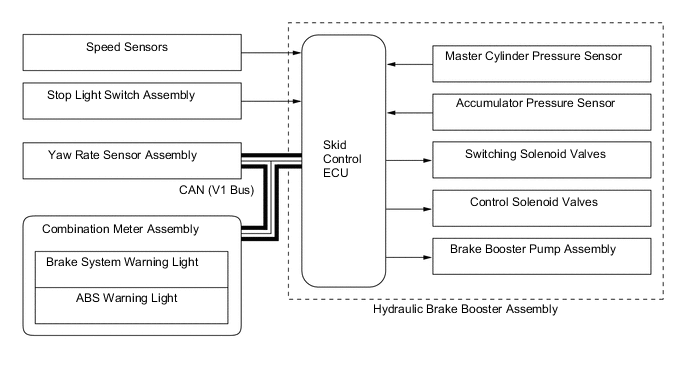
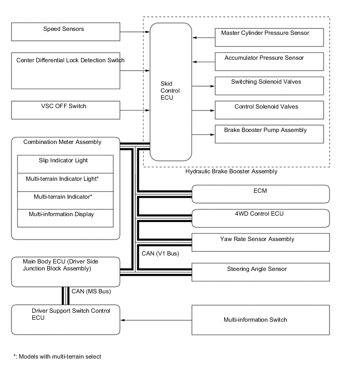
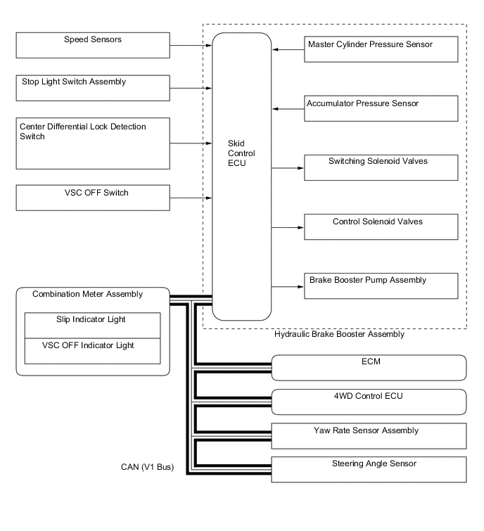
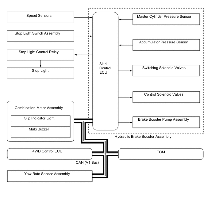
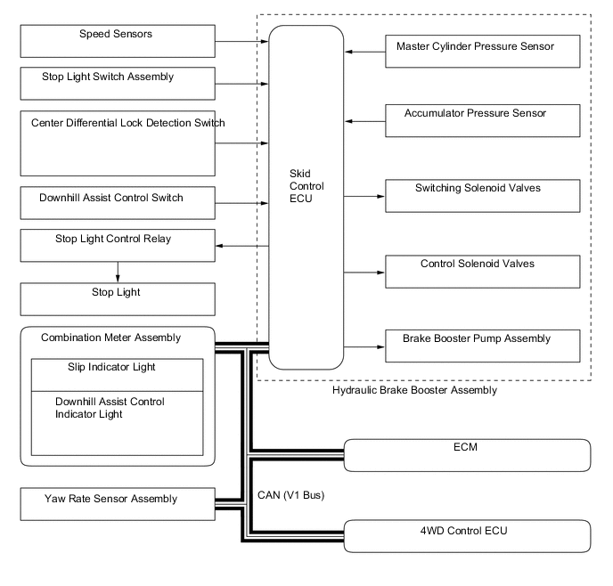
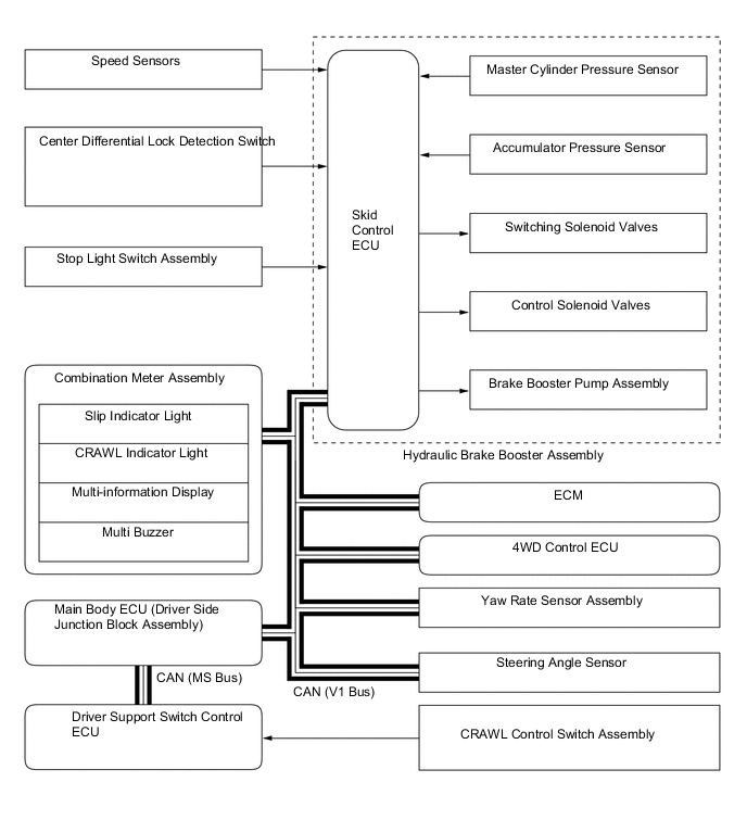
BRAKE CONTROL SYSTEM
-
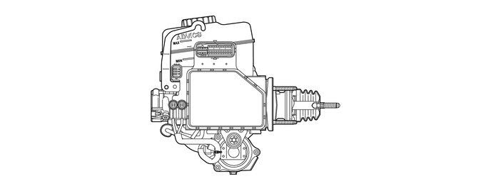
CONSTRUCTION
-
The brake actuator portion of the hydraulic brake booster consists of 4 switching solenoid valves, 8 control solenoid valves and a skid control ECU.
-
The pressure increase mode, the pressure holding mode, and the pressure reduction mode are effected based on the combination of these solenoid valves, which are turned on and off in order to control the hydraulic pressure that is applied to each of the wheel cylinders.
-
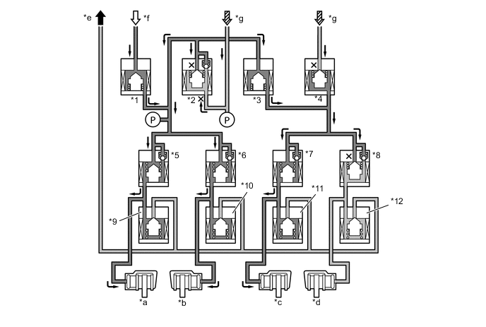
4 switching solenoid valves are used: 2 (SMCF, SREA) in the front brake fluid path, 1 (SREC) in the rear brake fluid path, and 1 (STR) in the accumulator fluid path. The switching solenoid valves open and close in accordance with the control signals from the skid control ECU in order to switch the respective brake fluid path.
-
The 8 control solenoid valves are used for the 4 wheels (2 types per wheel: pressure holding solenoid and pressure reduction solenoid).
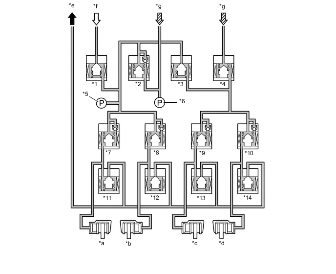
*1 Switching Solenoid Valve STR (Traction Solenoid Valve) *2 Switching Solenoid Valve SREC (Regulator Cut Solenoid Valve) *3 Switching Solenoid Valve SREA (Regulator Apply for Front Solenoid Valve) *4 Switching Solenoid Valve SMCF (Master Cut for Front Solenoid Valve) *5 Control Pressure Sensor (Models with Dynamic Radar Cruise Control System) *6 Master Cylinder Pressure Sensor *7 Control Solenoid Valve SRLH *8 Control Solenoid Valve SRRH *9 Control Solenoid Valve SFLH *10 Control Solenoid Valve SFRH *11 Control Solenoid Valve SRLR *12 Control Solenoid Valve SRRR *13 Control Solenoid Valve SFLR *14 Control Solenoid Valve SFRR *a Rear LH *b Rear RH *c Front LH *d Front RH *e To Brake Master Cylinder Reservoir *f From Brake Booster Accumulator Assembly *g From Brake Master Cylinder - -
-
-
OPERATION
-
ABS and EBD
-
Based on the signals received from the 4 speed sensors, the skid control ECU calculates the speed of each wheel, and checks wheel slipping conditions.
-
The skid control ECU compares the speed sensor signals of the front and rear, judges the slipping condition of the rear wheel, and operates the EBD.
-
When a wheel is about to lock, the ABS operation starts in order to regulate the hydraulic pressure at the wheel cylinders while switching between the 3 modes: pressure increase, pressure holding, and pressure reduction.
EBD Operation Item EBD Not Activated EBD Activated Increase Mode Holding Mode Reduction Mode Switching Solenoid Valve *1 STR Off (Closed) ← ← ← *2 SREC Off (Open) ← ← ← *3 SREA Off (Closed) ← ← ← *4 SMCF Off (Open) ← ← ← Control Solenoid Valve Front Brake LH *7 SFLH Off (Open) ← On (Closed) ← *11 SFLR Off (Closed) ← ← On (Open) *c Wheel Cylinder Pressure - Increases Holds Reduces Front Brake RH *8 SFRH Off (Open) ← On (Closed) ← *12 SFRR Off (Closed) ← ← ← *d Wheel Cylinder Pressure - - - - Rear Brake LH *5 SRLH Off (Open) On (Closed) ← ← *9 SRLR Off (Closed) ← ← ← *a Wheel Cylinder Pressure - - - - Rear Brake RH *6 SRRH Off (Open) On (Closed) ← ← *10 SRRR Off (Closed) ← ← ← *b Wheel Cylinder Pressure - - - - *e To Brake Master Cylinder Reservoir *f From Brake Booster Accumulator Assembly *g From Brake Master Cylinder 
ABS Operation Item ABS Not Activated ABS Activated Increase Mode Holding Mode Reduction Mode Switching Solenoid Valve *1 STR Off (Closed) ← ← ← *2 SREC Off (Open) ← ← ← *3 SREA Off (Closed) On (Open) ← ← *4 SMCF Off (Open) On (Closed) ← ← Control Solenoid Valve Front Brake LH *7 SFLH Off (Open) ← On (Closed) ← *11 SFLR Off (Closed) ← ← On (Open) *c Wheel Cylinder Pressure - Increases Holds Reduces Front Brake RH *8 SFRH Off (Open) ← On (Closed) ← *12 SFRR Off (Closed) ← ← Off (Open) *d Wheel Cylinder Pressure - Increases Holds Reduces Rear Brake LH *5 SRLH Off (Open) ← On (Closed) ← *9 SRLR Off (Closed) ← ← On (Open) *a Wheel Cylinder Pressure - Increases Holds Reduces Rear Brake RH *6 SRRH Off (Open) ← On (Closed) ← *10 SRRR Off (Closed) ← ← On (Open) *b Wheel Cylinder Pressure - Increases Holds Reduces *e To Brake Master Cylinder Reservoir *f From Brake Booster Accumulator Assembly *g From Brake Master Cylinder Tech Tips
While the front wheels are in the ABS operation, SREA and SMCF are on. While only rear wheels are in the ABS operation, SREA and SMCF are off.
-
-
Multi-terrain ABS
-
The skid control ECU calculates the speed and deceleration of each wheel, and checks the wheel slipping condition based on signals from the 4 speed sensors and the yaw rate sensor assembly as well as the engine output information transmitted from the ECM.
-
If the wheel is likely to lock, the skid control ECU controls the pressure holding solenoid valve and pressure reduction solenoid valve as multi-terrain ABS operation in the following 3 modes: increase mode, holding mode, and reduction mode.
Multi-terrain ABS Operation Item Multi-terrain ABS Not Activated Multi-terrain ABS Activated Increase Mode Holding Mode Reduction Mode Switching Solenoid Valve *1 STR Off (Closed) ← ← ← *2 SREC Off (Open) ← ← ← *3 SREA Off (Closed) On (Open) ← ← *4 SMCF Off (Open) On (Closed) ← ← Control Solenoid Valve Front Brake LH *7 SFLH Off (Open) ← On (Closed) ← *11 SFLR Off (Closed) ← ← On (Open) *c Wheel Cylinder Pressure - Increases Holds Reduces Front Brake RH *8 SFRH Off (Open) ← On (Closed) ← *12 SFRR Off (Closed) ← ← On (Open) *d Wheel Cylinder Pressure - Increases Holds Reduces Rear Brake LH *5 SRLH Off (Open) ← On (Closed) ← *9 SRLR Off (Closed) ← ← On (Open) *a Wheel Cylinder Pressure - Increases Holds Reduces Rear Brake RH *6 SRRH Off (Open) ← On (Closed) ← *10 SRRR Off (Closed) ← ← On (Open) *b Wheel Cylinder Pressure - Increases Holds Reduces *e To Brake Master Cylinder Reservoir *f From Brake Booster Accumulator Assembly *g From Brake Master Cylinder Tech Tips
-
While the front wheels are in the multi-terrain ABS operation, SREA and SMCF are on.
-
While only rear wheels are in the multi-terrain ABS operation, SREA and SMCF are off.
-
-
-
Brake Assist
-
If an emergency braking situation has occurred, it is detected by the skid control ECU based on the vehicle speed signal from the speed sensor, the brake pedal application speed from the master cylinder pressure sensor, and the signal representing the amount of pedal effort. Then, the skid control ECU actuates each solenoid valve. As a result, the pressure from the brake booster accumulator assembly is applied to the wheel cylinders. The accumulator pressure that is applied to the wheel cylinders generates a higher pressure than the master cylinder.

Brake Assist Operation Item Brake Assist Not Activated Brake Assist Activated Increase Mode Holding Mode Reduction Mode Switching Solenoid Valve *1 STR Off (Closed) On (Open) ← Off (Closed) *2 SREC Off (Open) On (Closed) ← Off (Open) *3 SREA Off (Closed) On (Open) ← ← *4 SMCF Off (Open) On (Closed) ← ← Control Solenoid Valve Front Brake LH *7 SFLH Off (Open) ← On (Closed) ← *11 SFLR Off (Closed) ← ← On (Open) *c Wheel Cylinder Pressure - Increases Holds Reduces Front Brake RH *8 SFRH Off (Open) ← On (Closed) ← *12 SFRR Off (Closed) ← ← On (Open) *d Wheel Cylinder Pressure - Increases Holds Reduces Rear Brake LH *5 SRLH Off (Open) ← On (Closed) ← *9 SRLR Off (Closed) ← ← On (Open) *a Wheel Cylinder Pressure - Increases Holds Reduces Rear Brake RH *6 SRRH Off (Open) ← On (Closed) ← *10 SRRR Off (Closed) ← ← On (Open) *b Wheel Cylinder Pressure - Increases Holds Reduces *e To Brake Master Cylinder Reservoir *f From Brake Booster Accumulator Assembly *g From Brake Master Cylinder
-
-
TRC
-
The fluid pressure that is generated by the brake booster pump assembly is regulated by the switching solenoid valves and control solenoid valves to the required pressure. Thus, the pressure to the wheel cylinders of the drive wheels is controlled in the following 3 modes: increase mode, holding mode, and reduction mode, to restrain the slippage of the drive wheels.
-
The skid control ECU outputs a TRC operation signal to the ECM. Upon receiving this signal, the ECM effects engine output control.
-
If the accumulator pressure drops during this operation, the skid control ECU receives the signals from the accumulator pressure sensor and actuates the brake booster pump assembly to ensure the proper accumulator pressure.
TRC Operation Item TRC Not Activated TRC Activated Increase Mode Holding Mode Reduction Mode Switching Solenoid Valve *1 STR Off (Closed) On (Open) ← Off (Closed) *2 SREC Off (Open) On (Closed) ← Off (Open) *3 SREA Off (Closed) On (Open) ← ← *4 SMCF Off (Open) On (Closed) ← ← Control Solenoid Valve Front Brake LH *7 SFLH Off (Open) ← On (Closed) ← *11 SFLR Off (Closed) ← ← On (Open) *c Wheel Cylinder Pressure - Increases Holds Reduces Front Brake RH *8 SFRH Off (Open) ← On (Closed) ← *12 SFRR Off (Closed) ← ← On (Open) *d Wheel Cylinder Pressure - Increases Holds Reduces Rear Brake LH *5 SRLH Off (Open) ← On (Closed) ← *9 SRLR Off (Closed) ← ← On (Open) *a Wheel Cylinder Pressure - Increases Holds Reduces Rear Brake RH *6 SRRH Off (Open) ← On (Closed) ← *10 SRRR Off (Closed) ← ← On (Open) *b Wheel Cylinder Pressure - Increases Holds Reduces *e To Brake Master Cylinder Reservoir *f From Brake Booster Accumulator Assembly *g From Brake Master Cylinder
-
-
A-TRC
-
Based on the vehicle speed that has been calculated from each speed sensor and the signals of the yaw rate and deceleration sensor, the skid control ECU computes the target control speed.
-
The skid control ECU compares the target control speed and the wheel speed to determine whether or not slippage exists. Upon detecting slippage, the skid control ECU controls the solenoid valve of the hydraulic brake booster assembly to control the brake fluid pressure that is applied to the slipping wheel. When the wheel speed becomes lower than the target control speed, the skid control ECU stops increasing the brake fluid pressure.
-
The fluid pressure control of the A-TRC independently controls the brake of each wheel by operating the individual solenoid valves in accordance with the signals received from the skid control ECU. The brake of each wheel is controlled in the following 3 modes: pressure increase, pressure holding, and pressure reduction modes.
A-TRC Operation Item A-TRC Not Activated A-TRC Activated Increase Mode Holding Mode Reduction Mode Switching Solenoid Valve *1 STR Off (Closed) On (Open) ← Off (Closed) *2 SREC Off (Open) On (Closed) ← Off (Open) *3 SREA Off (Closed) On (Open) ← ← *4 SMCF Off (Open) On (Closed) ← ← Control Solenoid Valve Front Brake LH *7 SFLH Off (Open) ← On (Closed) ← *11 SFLR Off (Closed) ← ← On (Open) *c Wheel Cylinder Pressure - Increases Holds Reduces Front Brake RH *8 SFRH Off (Open) ← On (Closed) ← *12 SFRR Off (Closed) ← ← On (Open) *d Wheel Cylinder Pressure - Increases Holds Reduces Rear Brake LH *5 SRLH Off (Open) ← On (Closed) ← *9 SRLR Off (Closed) ← ← On (Open) *a Wheel Cylinder Pressure - Increases Holds Reduces Rear Brake RH *6 SRRH Off (Open) ← On (Closed) ← *10 SRRR Off (Closed) ← ← On (Open) *b Wheel Cylinder Pressure - Increases Holds Reduces *e To Brake Master Cylinder Reservoir *f From Brake Booster Accumulator Assembly *g From Brake Master Cylinder
-
-
VSC
-
Based on the information provided by various sensors, switches, and the ECM, the skid control ECU determines the vehicle's yaw moment. Then, the skid control ECU controls the fluid pressure that is generated by the brake booster pump assembly and applies it by way of the solenoid valves to the brake wheel cylinder of each wheel in the following 3 modes: pressure increase, pressure holding, and pressure reduction modes. As a result, the tendency of the front wheels or the rear wheels to skid is restrained.
-
At this time, the skid control ECU outputs a VSC operation signal to the ECM and the combination meter. Upon receiving this signal, the ECM controls the engine output. The slip indicator light will blink in the combination meter assembly.
-
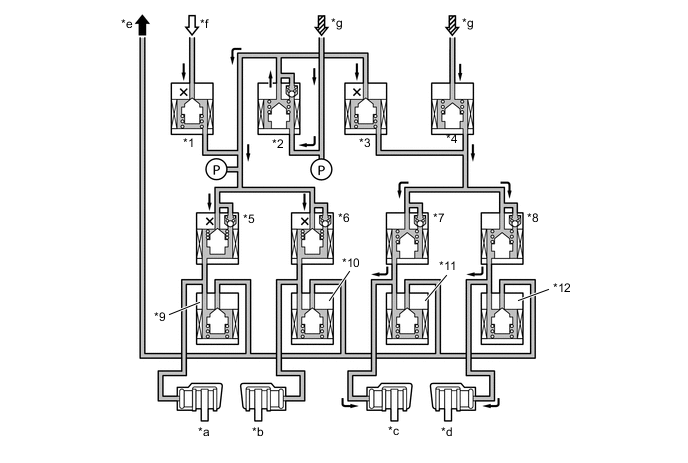
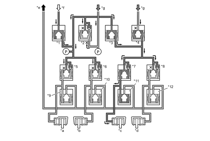
During front wheel skid restraining control, the brakes of the rear wheels and front wheel of the outer side of the turn are applied. Also, depending on whether the brake is on or off and on the condition of the vehicle, there are circumstances in which the brake might not be applied to the wheels even if those wheels are targeted for braking. The diagram below shows the hydraulic circuit in the pressure increase mode, as it restrains a front wheel skid while the vehicle is making a right turn.
VSC Operation (Turning Right) Item VSC Not Activated VSC Activated Increase Mode Holding Mode Reduction Mode Switching Solenoid Valve *1 STR Off (Closed) On (Open) ← Off (Closed) *2 SREC Off (Open) On (Closed) ← Off (Open) *3 SREA Off (Closed) On (Open) ← ← *4 SMCF Off (Open) On (Closed) ← ← Control Solenoid Valve Front Brake LH *7 SFLH Off (Open) ← On (Closed) ← *11 SFLR Off (Closed) ← ← On (Open) *c Wheel Cylinder Pressure - Increases Holds Reduces Front Brake RH *8 SFRH Off (Open) On (Closed) ← ← *12 SFRR Off (Closed) ← ← ← *d Wheel Cylinder Pressure - - - - Rear Brake LH *5 SRLH Off (Open) ← On (Closed) ← *9 SRLR Off (Closed) ← ← On (Open) *a Wheel Cylinder Pressure - Increases Holds Reduces Rear Brake RH *6 SRRH Off (Open) ← On (Closed) ← *10 SRRR Off (Closed) ← ← On (Open) *b Wheel Cylinder Pressure - Increases Holds Reduces *e To Brake Master Cylinder Reservoir *f From Brake Booster Accumulator Assembly *g From Brake Master Cylinder -
During rear wheel skid restraining control, the front wheel brake of the outer side of the turn is applied. Also, depending on whether the brake is on or off and on the condition of the vehicle, there are circumstances in which the brake might be applied to the rear brake of the outer side of the turn. The diagram below shows the hydraulic circuit in the pressure increase mode, as it restrains a rear wheel skid while the vehicle is making a right turn.
VSC Operation (Turning Right) Item VSC Not Activated VSC Activated Increase Mode Holding Mode Reduction Mode Switching Solenoid Valve *1 STR Off (Closed) On (Open) ← Off (Closed) *2 SREC Off (Open) On (Closed) ← Off (Open) *3 SREA Off (Closed) On (Open) ← ← *4 SMCF Off (Open) On (Closed) ← ← Control Solenoid Valve Front Brake LH *7 SFLH Off (Open) ← On (Closed) ← *11 SFLR Off (Closed) ← ← On (Open) *c Wheel Cylinder Pressure - Increases Holds Reduces Front Brake RH *8 SFRH Off (Open) On (Closed) ← ← *12 SFRR Off (Closed) ← ← ← *d Wheel Cylinder Pressure - - - - Rear Brake LH *5 SRLH Off (Open) ← On (Closed) ← *9 SRLR Off (Closed) ← ← On (Open) *a Wheel Cylinder Pressure - - - - Rear Brake RH *6 SRRH Off (Open) ← ← ← *10 SRRR Off (Closed) ← ← On (Open) *b Wheel Cylinder Pressure - Increases Holds Reduces *e To Brake Master Cylinder Reservoir *f From Brake Booster Accumulator Assembly *g From Brake Master Cylinder
-
-
Hill-start Assist Control
-
Based on the information provided by various sensors, switches, and the ECM, the skid control ECU computes the backward movement of the vehicle that occurs when the vehicle starts off on a hill. Then, the skid control ECU controls the fluid pressure that is generated by the pump and pump motor and applies it by way of the solenoid valves to the brake wheel cylinder of each wheel in the following 3 modes: pressure increase, pressure holding, and pressure reduction modes.
-
The skid control ECU determines the state of the backward movement of the vehicle while the driver is attempting to drive uphill, based on the speed sensors and the neutral start switch.
-
The skid control ECU determines the gradient of the hill, the acceleration state of the vehicle, the locked state and the rotation direction of each wheel through the speed sensors and the yaw rate sensor assembly. Then, the skid ECU computes the amount of brake control that will prevent the wheels from locking.
-
During this operation, the skid control ECU outputs a hill-start assist control operation signal to the combination meter. This causes the slip indicator light to blink, sends signals to the stop light control relay which turns on the stop light.
-
The hill-start assist control operates for approximately five seconds. At this time, the skid control ECU informs the driver by the slow and intermittent sound of the skid control buzzer assembly. After this, the skid control ECU alerts the driver by using the quick and intermittent sound of the skid control buzzer assembly, and gradually releases the brake hydraulic pressure in order to end the hill-start assist control operation.
Hill-start Assist Control Operation Item Hill-start Assist Control Not Activated Hill-start Assist Control Activated Increase Mode Holding Mode Reduction Mode Switching Solenoid Valve *1 STR Off (Closed) On (Open) ← Off (Closed) *2 SREC Off (Open) On (Closed) ← Off (Open) *3 SREA Off (Closed) On (Open) ← ← *4 SMCF Off (Open) On (Closed) ← ← Control Solenoid Valve Front Brake LH *7 SFLH Off (Open) ← On (Closed) ← *11 SFLR Off (Closed) ← ← On (Open) *c Wheel Cylinder Pressure - Increases Holds Reduces Front Brake RH *8 SFRH Off (Open) ← On (Closed) ← *12 SFRR Off (Closed) ← ← On (Open) *d Wheel Cylinder Pressure - Increases Holds Reduces Rear Brake LH *5 SRLH Off (Open) ← On (Closed) ← *9 SRLR Off (Closed) ← ← On (Open) *a Wheel Cylinder Pressure - Increases Holds Reduces Rear Brake RH *6 SRRH Off (Open) ← On (Closed) ← *10 SRRR Off (Closed) ← ← On (Open) *b Wheel Cylinder Pressure - Increases Holds Reduces *e To Brake Master Cylinder Reservoir *f From Brake Booster Accumulator Assembly *g From Brake Master Cylinder
-
-
Downhill Assist Control
-
Based on the information provided by various sensors, switches, and the engine ECU, the skid control ECU determines the conditions that enable downhill assist control operation. Then, the skid control ECU controls the fluid pressure that is generated by the brake booster pump assembly and applies it by way of the solenoid valve to the brake wheel cylinder of each wheel in the following 3 modes: pressure increase, pressure holding and pressure reduction modes.
-
The skid control ECU computes the vehicle speed, travel direction, and the gradient of the hill in accordance with the signals that are input by the speed sensor and the yaw rate sensor assembly, and effects brake control to attain the target vehicle speed. The target vehicle speed is determined by the direction of the vehicle.
Downhill Assist Control Target Vehicle Speed Travel Direction Forward 5 km/h to 7 km/h (3 mph to 4 mph) Backward 3 km/h to 5 km/h (2 mph to 3 mph) -
During the downhill assist control operation, the skid control ECU outputs signals to the stop light control relay to cause the stop light to turn on, and to the combination meter to cause the slip indicator light to blink.
Downhill Assist Control Operation Item Downhill Assist Control Not Activated Downhill Assist Control Activated Increase Mode Holding Mode Reduction Mode Switching Solenoid Valve *1 STR Off (Closed) On (Open) ← Off (Closed) *2 SREC Off (Open) On (Closed) ← Off (Open) *3 SREA Off (Closed) On (Open) ← ← *4 SMCF Off (Open) On (Closed) ← ← Control Solenoid Valve Front Brake LH *7 SFLH Off (Open) ← On (Closed) ← *11 SFLR Off (Closed) ← ← On (Open) *c Wheel Cylinder Pressure - Increases Holds Reduces Front Brake RH *8 SFRH Off (Open) ← On (Closed) ← *12 SFRR Off (Closed) ← ← On (Open) *d Wheel Cylinder Pressure - Increases Holds Reduces Rear Brake LH *5 SRLH Off (Open) ← On (Closed) ← *9 SRLR Off (Closed) ← ← On (Open) *a Wheel Cylinder Pressure - Increases Holds Reduces Rear Brake RH *6 SRRH Off (Open) ← On (Closed) ← *10 SRRR Off (Closed) ← ← On (Open) *b Wheel Cylinder Pressure - Increases Holds Reduces *e To Brake Master Cylinder Reservoir *f From Brake Booster Accumulator Assembly *g From Brake Master Cylinder
-
-
CRAWL
-
Based on the information provided by various sensors, switches, and the ECM, the skid control ECU determines the conditions that enable the CRAWL to operate. The skid control ECU computes the target vehicle speed (approximately 1 km/h to 6 km/h, 1 mph to 3.7 mph) to control the vehicle speed, and the target wheel speeds to control the wheel slipping. The target vehicle speed can be changed using the CRAWL speed selector switch.
-
When the vehicle speed differs from the target speed, the engine output is regulated. When the wheel speeds differ from the target speeds, the hydraulic brake pressure of the wheels is regulated.
-
The skid control ECU controls the fluid pressure that is generated by the brake booster pump assembly and applies it by way of the solenoid valves to the brake wheel cylinder of each wheel in the following 3 modes: pressure increase, pressure holding, and pressure reduction modes.
CRAWL Operation Item CRAWL Not Activated CRAWL Activated Increase Mode Holding Mode Reduction Mode Switching Solenoid Valve *1 STR Off (Closed) On (Open) ← Off (Closed) *2 SREC Off (Open) On (Closed) ← Off (Open) *3 SREA Off (Closed) On (Open) ← ← *4 SMCF Off (Open) On (Closed) ← ← Control Solenoid Valve Front Brake LH *7 SFLH Off (Open) ← On (Closed) ← *11 SFLR Off (Closed) ← ← On (Open) *c Wheel Cylinder Pressure - Increases Holds Reduces Front Brake RH *8 SFRH Off (Open) ← On (Closed) ← *12 SFRR Off (Closed) ← ← On (Open) *d Wheel Cylinder Pressure - Increases Holds Reduces Rear Brake LH *5 SRLH Off (Open) ← On (Closed) ← *9 SRLR Off (Closed) ← ← On (Open) *a Wheel Cylinder Pressure - Increases Holds Reduces Rear Brake RH *6 SRRH Off (Open) ← On (Closed) ← *10 SRRR Off (Closed) ← ← On (Open) *b Wheel Cylinder Pressure - Increases Holds Reduces *e To Brake Master Cylinder Reservoir *f From Brake Booster Accumulator Assembly *g From Brake Master Cylinder
-
-