FOUR WHEEL DRIVE CONTROL SYSTEM
-
FUNCTION OF MAIN COMPONENTS
Component Function Transfer Shift Actuator Assembly H-L Shift Motor Switches the transfer gear ratio between high and low in accordance with signals from the 4WD control ECU. H-L Limit Switch Detects the position of the H-L shift motor and transmits a signal to the 4WD control ECU. Center Differential Lock Shift Motor Switches the center differential between free and lock in accordance with signals from the 4WD control ECU. Center Differential Lock Limit Switch Detects the position of the center differential lock shift motor and transmits a signal to the 4WD control ECU. Center Differential Lock Position Switch Detects the lock position of the center differential and transmits a signal to the 4WD control ECU and so on. Transfer Position Switch Switches the transfer gear ratio between high and low and transmits a signal to the 4WD control ECU. Center Differential Lock Switch Switches the center differential between free and lock and transmits a signal to the 4WD control ECU. 4WD Control ECU Controls each shift motor in response to a signal from each switch. ECM Transmits a shift position signal to the 4WD control ECU via CAN. Combination Meter Assembly 4LO Indicator Light
-
Blinks while switching the transfer gear ratio between high and low, and turns on when in low.
-
Blinks when the switching conditions are not met while switching the transfer gear ratio between high and low.
Center Differential Lock Indicator Light
-
Blinks while switching the center differential between free and lock, and turns on when in lock.
-
Blinks when the switching conditions are not met while switching the center differential between free and lock.
VSC OFF Indicator Light Turns on in accordance with the drive mode when VSC function is not operating. Multi Buzzer Sounds when the switching conditions are not met while switching the drive mode. -
-
SYSTEM CONTROL
-
High-low Switching of Transfer Gear Ratio
-
High Position
-
In the high position, the internal gear teeth of the transfer high and low clutch sleeve mesh with the transfer clutch hub spline piece.
-
Also, the transfer high and low clutch sleeve is connected to the center differential case.
-
The rotation of the transfer input shaft is transmitted to the planetary sun gear, transfer clutch hub spline piece, transfer high and low clutch sleeve, and the differential case.
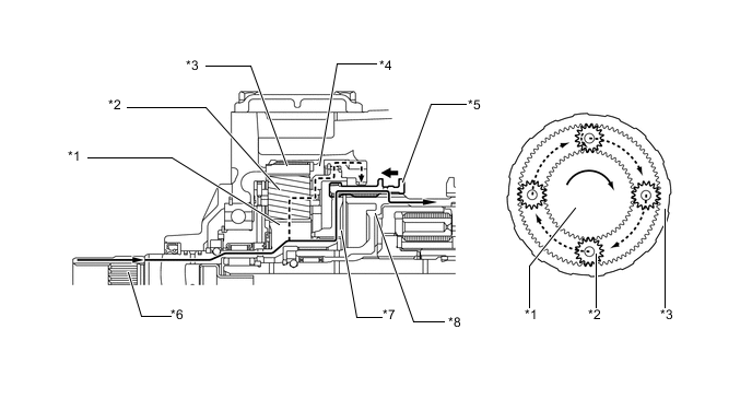
*1 Planetary Sun Gear *2 Planetary Pinion Gear *3 Planetary Ring Gear *4 Planetary Carrier *5 Transfer High and Low Clutch Sleeve *6 Transfer Input Shaft *7 Transfer Clutch Hub Spline Piece *8 Center Differential Case -
-
Low Position
-
In the low position, the external teeth of the transfer high and low clutch sleeve mesh with the transfer low planetary spline piece.
-
Also, the transfer high and low clutch sleeve is connected to the center differential case.
-
The rotation of the transfer input shaft is transmitted in a reduced form to the planetary sun gear, planetary pinion gears, planetary pinion gear shafts, planetary carrier, transfer low planetary spline piece, transfer high and low clutch sleeve, and center differential case.
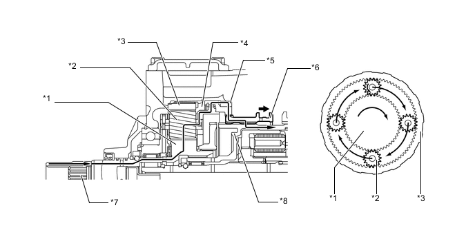
*1 Planetary Sun Gear *2 Planetary Pinion Gear *3 Planetary Ring Gear *4 Planetary Carrier *5 Transfer Low Planetary Spline Piece *6 Transfer High and Low Clutch Sleeve *7 Transfer Input Shaft *8 Center Differential Case -
-
-
Free-lock Switching of Center Differential
-
Lock Position
-
In the lock position, the front drive clutch sleeve connects the center differential case and the transfer front drive spline piece to set the center differential to lock.
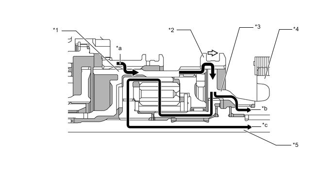
*1 Center Differential Case *2 Front Drive Clutch Sleeve *3 Transfer Front Drive Spline Piece *4 Front Drive Sprocket *5 Transfer Rear Output Shaft - - *a Input Torque *b Front Output Torque *c Rear Output Torque - - -
-
-
Operation of Center Differential
-
Normal Driving Operation
-
During normal driving (front wheel speed = rear wheel speed), the drive torque that is input by the differential case is transmitted (front: 40/rear: 60) as shown below, without involving the LSD function.
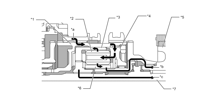
*1 Center Differential Case *2 Pinion Gear *3 Ring Gear *4 Planetary Carrier *5 Front Drive Sprocket *6 Sun Gear *7 Transfer Rear Output Shaft - *a Input Torque *b Front Output Torque *c Rear Output Torque - - -
-
Front Wheel Skid Driving Operation
-
During front wheel skid driving (front wheel speed > rear wheel speed) when a rotational difference exists between the sun gear and the ring gear, the distribution of the drive torque that is input by the center differential case changes instantly before the torque is transmitted, as follows:
-
The sun gear transmits torque to the planetary carrier while pushing on the No. 4 clutch plate. The planetary carrier transmits this torque to the ring gear from the center differential case via the No. 1 clutch plate.
-
The ring gear outputs torque while pushing on the No. 1 clutch plate.
-
These LSD functions change the torque distribution.
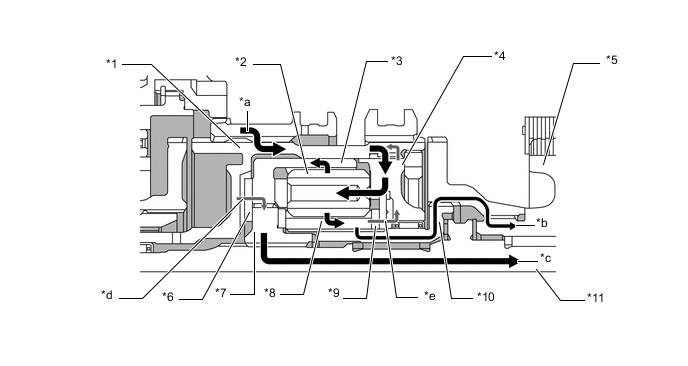
*1 Center Differential Case *2 Pinion Gear *3 Ring Gear *4 Planetary Carrier *5 Front Drive Sprocket *6 No. 1 Clutch Plate *7 Coupling *8 Sun Gear *9 No. 4 Clutch Plate *10 Transfer Clutch Hub *11 Transfer Rear Output Shaft - - *a Input Torque *b Front Output Torque *c Rear Output Torque *d Pushing on No. 1 Clutch Plate *e Pushing on No. 4 Clutch Plate - - -
-
Rear Wheel Skid Driving Operation
-
During rear wheel skid driving (front wheel speed < rear wheel speed), when a rotational difference exists between the sun gear and the ring gear, the distribution of the drive torque that is input by the center differential case changes instantly before the torque is transmitted, as follows:
-
The ring gear transmits torque to the center differential case while pushing on the No. 1 clutch plate. The center differential case transmits this torque from the planetary carrier to the sun gear via the No. 4 clutch plate.
-
The sun gear outputs torque while pushing on the No. 4 clutch plate.
-
These LSD functions change the torque distribution.
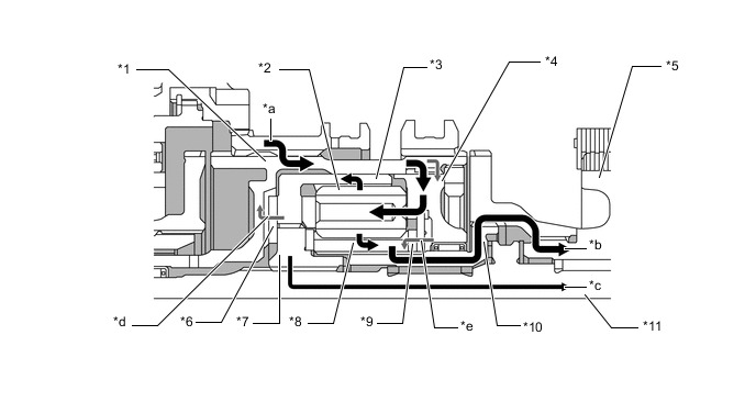
*1 Center Differential Case *2 Pinion Gear *3 Ring Gear *4 Planetary Carrier *5 Front Drive Sprocket *6 No. 1 Clutch Plate *7 Coupling *8 Sun Gear *9 No. 4 Clutch Plate *10 Transfer Clutch Hub *11 Transfer Rear Output Shaft - - *a Input Torque *b Front Output Torque *c Rear Output Torque *d Pushing on No. 1 Clutch Plate *e Pushing on No. 4 Clutch Plate - - -
-
-
Operating Condition
-
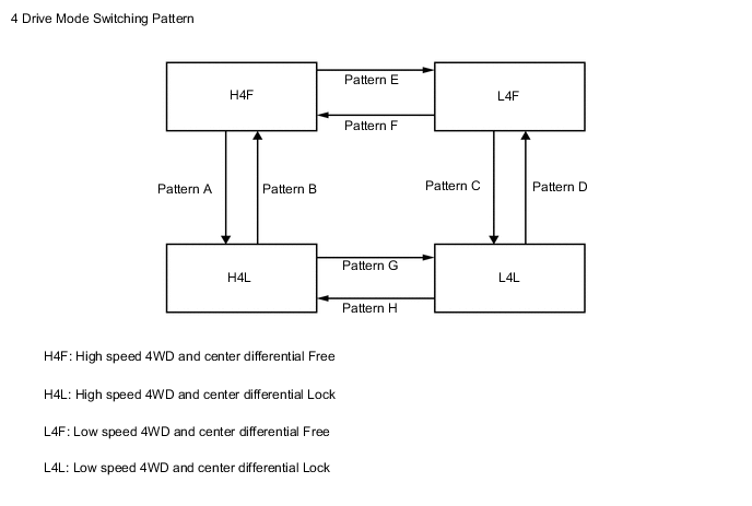
4 Drive Mode
-
The drive mode switching pattern of the 4WD system is as shown in the illustration below:
-
The center differential can be switched between free and lock (switching patterns A to D) when the vehicle is running. However, the center differential should not be switched from free to lock when the vehicle is turning or the tires are spinning.
-
The transfer gear ratio can be switched between high and low (switching patterns E to H) only when the vehicle is stationary and the shift lever is in N.
-
TRC or VSC function in the brake control system may be stopped, depending on the drive mode. For details, see the Brake Control/Dynamic Control Systems section.
-
-
-