AUTOMATIC TRANSMISSION SYSTEM
-
FUNCTION OF MAIN COMPONENTS
Component Function ATF Warmer Warms up the ATF quickly. Air-cooled Type ATF Cooler*1 Cools down the ATF. Torque Converter Assembly
-
Transmits the engine power to the transmission.
-
Increases engine torque.
Oil Pump Provides oil pressure necessary for the transmission operation. No. 1 Clutch (C1)
Connects the input shaft, F4and the intermediate shaft.
No. 2 Clutch (C2)
Connects the input shaft and the center planetary carrier. No. 3 Clutch (C3)
Connects the input shaft and the front planetary sun gear. No. 4 Clutch (C4)
Connects the input shaft and the intermediate shaft. No. 1 Brake (B1)
Prevents the front planetary carrier from turning either clockwise or counterclockwise. No. 2 Brake (B2)
Prevents the front and center planetary ring gears from turning either clockwise or counterclockwise. No. 3 Brake (B3)
Prevents the outer race of F2from turning both clockwise and counterclockwise.
No. 4 Brake (B4)
Prevents the center planetary carrier and the rear planetary ring gear from turning either clockwise or counterclockwise. No. 1 1-way Clutch (F1)
Prevents the front planetary carrier from turning counterclockwise. No. 2 1-way Clutch (F2)
Prevents the front planetary sun gear from turning counterclockwise when B3is operating.
No. 3 1-way Clutch (F3)
Prevents the center planetary carrier and the rear planetary ring gear from turning counterclockwise. No. 4 1-way Clutch (F4)
Prevents the intermediate shaft from turning counterclockwise. Planetary Gears Change the power transmission route in accordance with clutch and brake operation, and increase or decrease output shaft revolution accordingly. Shift Solenoid Valve (S1) Switches the 1-2 shift valve and the SL1 relay valve. Shift Solenoid Valve (S2) Switches the 2-3 shift valve and the 5-6 shift valve. Shift Solenoid Valve (S3) Switches the 3-4 shift valve. Shift Solenoid Valve (S4) Switches the 4-5 shift valve, the SL1 relay valve and the reverse sequence valve. Shift Solenoid Valve (SR) Switches the clutch apply relay valve and the B1 relay valve. Shift Solenoid Valve (SL1)
-
Controls clutch pressure.
-
Controls accumulator back pressure.
Shift Solenoid Valve (SL2) Controls brake pressure. Line Pressure Control Solenoid Assembly (SLT)
-
Controls line pressure.
-
Controls accumulator back pressure.
Lock-up Control Solenoid Assembly (SLU) Controls lock-up clutch pressure. ATF Temperature Sensors Detect the ATF temperature. Transmission Revolution Sensor (NT) Detects the input speed of the transmission. Transmission Revolution Sensor (SP2) Detects the output speed of the transmission. Park/Neutral Position Switch Assembly Detects the shift lever position (P, R, N, D). Transmission Control Switch
-
Detects that the shift lever is in S.
-
Detects the driver's shift-up and shift-down operations when the shift lever is in S.
Multi-information Switch Switches the screen of the multi-information display. ECM
-
Controls each shift solenoid valve and engine output in response to a signal from each sensor and switch.
-
When the ECM detects a malfunction, it makes a diagnosis and memorizes the failed section.
4WD Control ECU Sends a drive mode signal to the ECM. Air Conditioning Amplifier Assembly Sends a shift-up tardiness control signal to the ECM. Driving Support ECU Assembly*2 Sends a shifting control request signal to the ECM. Driving Support Switch Control ECU
-
Sends a 2nd start mode signal to the ECM.
-
Sends a multi-terrain select control signal to the ECM.*3
Combination Meter Assembly Shift Display
-
Indicates the shift lever position.
-
Indicates to inform the driver of driving in D mode or S mode.
-
Indicates the shift range (S1 to S6).
MIL Illuminates or blinks to inform the driver when the ECM detects a malfunction. 2nd Start Indicator Light Illuminates when the driver selects the 2nd start mode. Multi-information Display
-
Displays the 2nd start mode select.
-
Warns the driver by displaying a message when the ATF is at a high temperature.
-
Displays a Diagnostic Trouble Code (DTC).
Master Warning Light Warns the driver by lighting up when a message is shown on the multi-information display. Multi Buzzer
-
Sounds when shift-down operation is rejected in S mode.
-
Warns the driver by sounding when a message is shown on the multi-information display.
-
*1: Models with air-cooled type ATF cooler
-
*2: Models with dynamic radar cruise control system
-
*3: Models with multi-terrain select
-
-
SYSTEM CONTROL
Electronic Control of Automatic Transmission Control Function Shift Timing Control The ECM sends current to shift solenoid valves S1, S2, S3, S4 and/or SR based on signals from various sensors in order to shift the gears. Line Pressure Control Actuates the shift solenoid valve SLT to control the line pressure in accordance with information from the ECM and the operating conditions of the transmission. Clutch Pressure Optimal Control The shift solenoid valves SL1, SL2 and SLT minutely control the clutch pressure in accordance with the engine output and driving conditions of the transmission. Clutch to Clutch Pressure Control Controls the pressure that is applied directly to B2brake and C3clutch by actuating the shift solenoid valves SL1 and SL2 in accordance with the ECM signals.
Orifice Switching Control Prevents the oil pump from drawing air during extremely low temperatures while in 1st gear. Vehicle Lift Control To restrain the upward movement of the vehicle when the shift lever is moved from D to N, the clutch release speed has been optimized. Shift Down Control In order to ensure a smooth shift feel during downshifting to accelerate the vehicle, the hydraulic passages and control have been optimized. Engine Torque Control Retards the engine ignition timing temporarily to improve shift feeling while upshifts or downshifts occur. Powertrain Cooperative Control Controls both the shift control and engine output control in an integrated way, achieving excellent shift characteristics and driveability. Coast Downshift Control To prevent engine speed from decreasing and thereby maintain fuel cut, the ECM performs downshifts before fuel cut ends. Lock-up Timing Control The ECM sends current to the shift solenoid valve SLU based on signals from various sensors and engages or disengages the lock-up clutch. Flex Lock-up Clutch Control Controls the shift solenoid valve SLU, provides an intermediate mode for when the lock-up clutch is between on and off, and increases the operating range of the lock-up clutch to improve fuel economy. Artificial Intelligence-shift Control (AI-shift Control) Based on the signals from various sensors, the ECM determines the road conditions and the intention of the driver. Then, an appropriate shift pattern is automatically determined, thus improving driveability. Multi-mode Automatic Transmission The ECM appropriately controls the automatic transmission in accordance with the shift range position selected while the shift lever is in S.
-
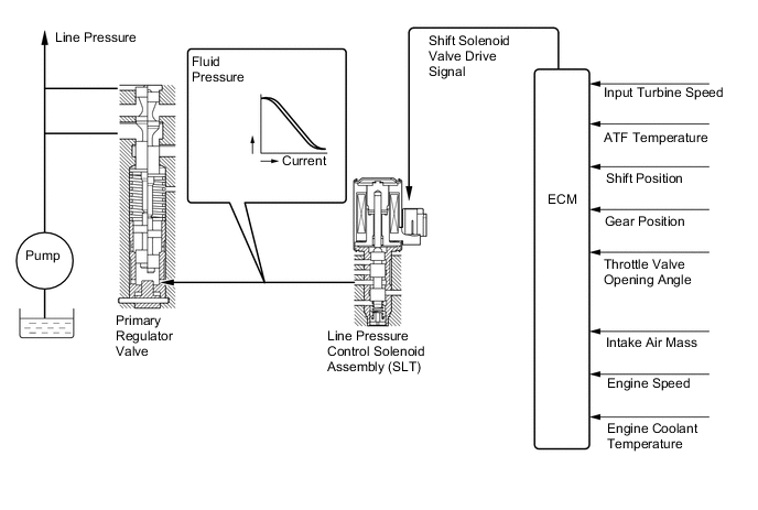
Line Pressure Control
-
In order to obtain a predetermined line pressure characteristic in accordance with each sensor signal, the ECM activates the shift solenoid valve SLT to regulate the throttle pressure.
-
This makes it possible for the primary regulator valve to precisely and minutely control the line pressure in accordance with the engine output, thus providing smoother shift characteristics.
-
-
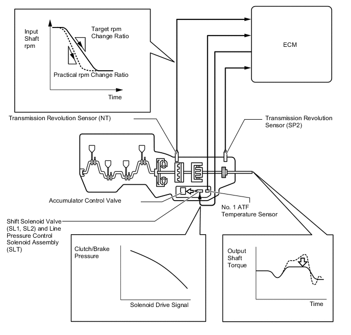
Clutch Pressure Optimal Control
-
The ECM monitors the signals from various types of sensors, such as the transmission revolution sensor (NT), allowing shift solenoid valves SL1, SL2 and SLT to minutely control the clutch pressure in accordance with engine output and driving conditions. As a result, smooth shift characteristics are achieved.
-
-
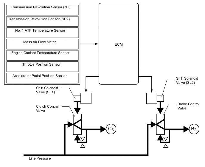
Clutch to Clutch Pressure Control
-
This control is used for shifting from 5th to 6th gear and from 6th to 5th gear.
-
The ECM actuates shift solenoid valves SL1 and SL2 in accordance with various signals. The output from these shift solenoid valves acts directly on control valves B2and C3in order to regulate the line pressure that acts on the B2brake and C3clutch.
-
High response and excellent shift characteristics have been achieved.
-
-
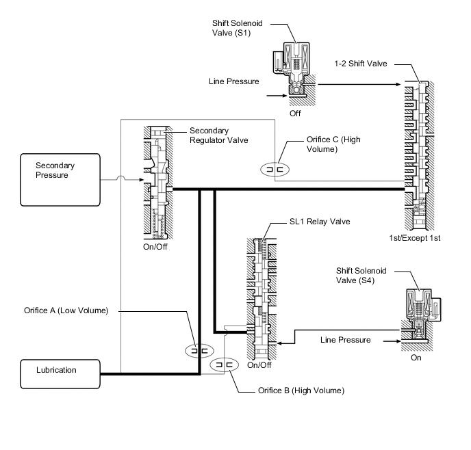
Orifice Switching Control
-
At extremely low temperatures, the ATF viscosity increases (becomes thick), making the oil pump susceptible to cavitation. For this reason, the orifice switching control reduces the volume of ATF in the hydraulic circuit and increases the volume of ATF drawn by the oil pump, in order to prevent the oil pump from cavitating.
-
While stopped in the 1st gear, the ECM turns off the shift solenoid valve S1 and turns on the shift solenoid valve S4 (which is normally off) in order to apply the line pressure to the 1-2 shift valve and the SL1 relay valve. The 1-2 shift valve and the SL1 relay valve close the ATF passage for the secondary pressure from the secondary regulator valve, thus causing the secondary pressure to pass through orifice "A". As a result, the volume of ATF in the hydraulic circuit is reduced.
-
While stopped in a gear other than 1st, the secondary pressure from the secondary regulator valve travels through either or both of the 1-2 shift valve and SL1 relay valve, and passes through orifices B and C. As a result, the volume of the ATF in the hydraulic circuit is not reduced.
-
-
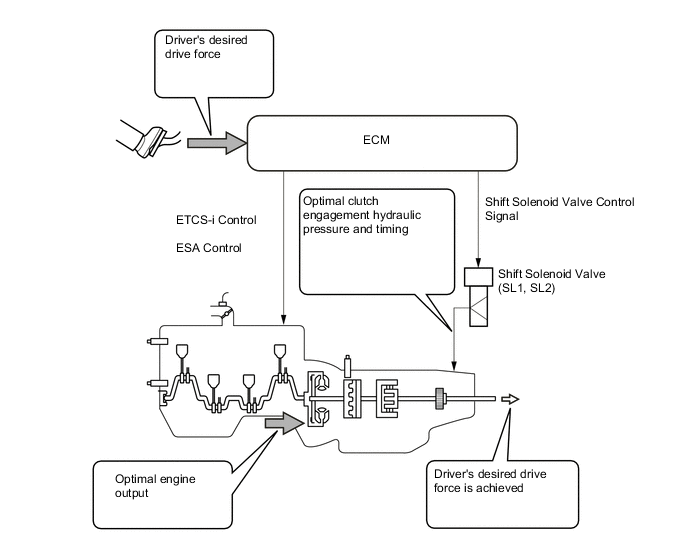
Powertrain Cooperative Control
-
Through cooperative control with Electronic Throttle Control System-intelligent (ETCS-i) and Electronic Spark Advance (ESA), and electronic control of the engagement and release speed of the clutch and brake hydraulic pressures, excellent response and shift shock reduction have been achieved.
-
-
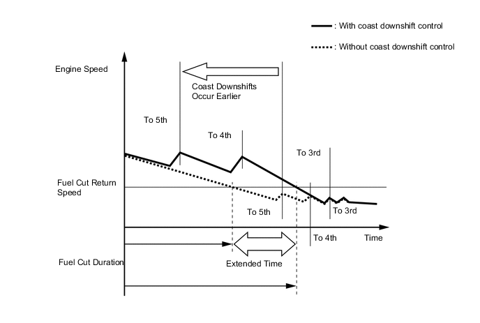
Coast Downshift Control
-
The ECM performs downshift control to prevent the engine speed from decreasing, thus keeping fuel cut control operating for as long as possible. In this way, fuel economy is improved.
-
For this control, when the vehicle is in 6th gear and starts decelerating, the transmission downshifts from 6th to 5th and from 5th to 4th before fuel cut control ends so that fuel cut control continues operating.
-
-
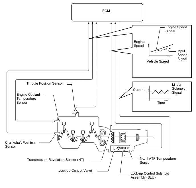
Lock-up Timing Control
-
The ECM operates the lock-up timing control in order to improve the fuel consumption performance in the 5th or 6th gear when the shift lever is in D or in the S6 range, and in the top gear when the shift lever is in the S5 or S4 range.
Lock-up Timing Control Operation Gear Shift Lever Position or Shift Range D, S6 S5 S4 1st X X X 2nd X X X 3rd X X X 4th X* X* ○ 5th ○ ○ - 6th ○ - - Tech Tips
○: Operates
X: Does not operate
-: Not applicable
*: Lock-up operation is performed when the 4th gear is held during the operation of the AI-shift control or the cruise control system.
-
-
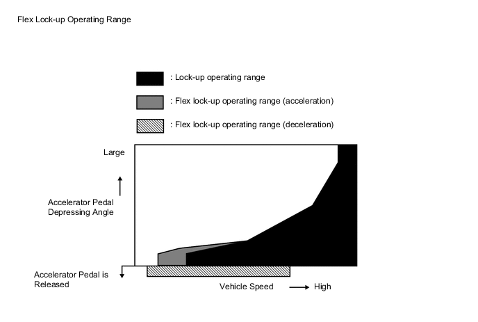
Flex Lock-up Clutch Control
-
In the low-to-mid-speed range, this flex lock-up clutch control regulates the shift solenoid valve SLU to provide an intermediate mode between the on and off operations of the lock-up clutch in order to improve the energy transmitting efficiency. As a result, the operating range of the lock-up clutch has been increased and fuel economy has been improved. The flex lock-up clutch control operates in 3rd, 4th, 5th and 6th gears when the shift lever is in D or in the S6 range, in 3rd, 4th and 5th gears when the shift lever is in the S5 range, and in 3rd and 4th gears when the shift lever is in the S4 range.
-
Even when the vehicle is decelerating (the accelerator pedal is released), the flex lock-up clutch control operates in 4th, 5th and 6th gears. Therefore, the fuel-cut area of the engine has been expanded and fuel economy has been improved.
Flex Lock-up Clutch Control Operation Gear Shift Lever Position or Shift Range D, S6 S5 S4 1st X X X 2nd X X X 3rd ○ ○ ○ 4th ○* ○* ○* 5th ○* ○* - 6th X* - - Tech Tips
○: Operates
X: Does not operate
-: Not applicable
*: Flex lock-up clutch control operates during deceleration.
-
-
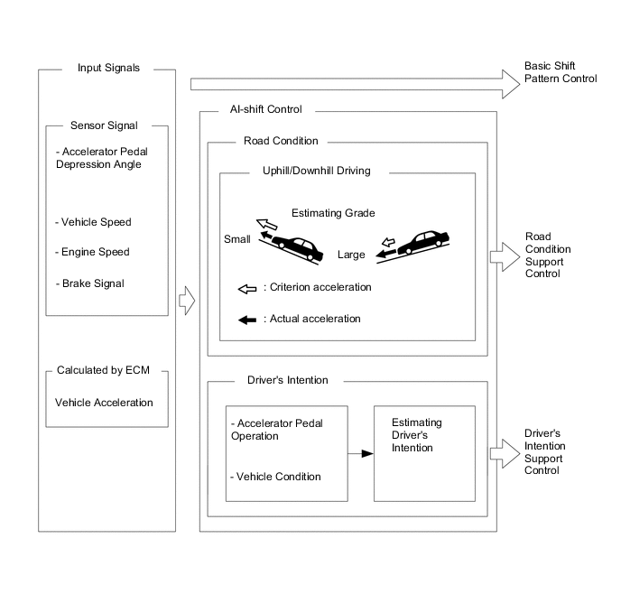
Artificial Intelligence-shift Control (AI-shift Control)
-
The AI-shift control determines optimal transmission control based on input signals and automatically changes the shift pattern. As a result, a high caliber of transmission operation is achieved.
-
The AI-shift control includes a road condition support control and a driver's intention support control.
-
The AI-shift control is effected only with the shift lever in D, based on the accelerator pedal and brake operation data. The AI-shift control will be canceled when the shift lever is moved to a position other than D.
-
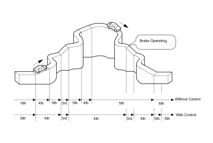
Under road condition support control, the ECM identifies the throttle valve opening angle, accelerator pedal opening angle and vehicle speed to determine whether the vehicle is being driven uphill or downhill. Unnecessary upshift is restrained to automatically achieve optimal drive force at all times while driving uphill. Downshift is automatically conducted to achieve optimal engine brake force, while driving downhill.
-
The driver's intention support control is estimated based on the accelerator pedal operation and vehicle condition, and a shift pattern that is well-suited to the driver is selected.
-
-
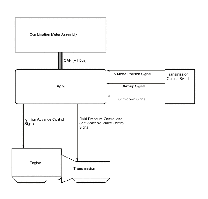
Multi-mode Automatic Transmission
-
Multi-mode automatic transmission is designed to allow the driver to switch the shift ranges (multi-mode transmission is not for manually selecting single gears). After moving the shift lever to S, the driver can select the desired shift range by moving the shift lever to "+" (forwards) or "-" (backwards). Thus, the driver is able to shift gears with a manual-like feel.
-
The driver selects S mode by moving the shift lever. At this time, the S4 or S5 range is selected in accordance with the vehicle speed (S3 or S2 range may be selected in accordance with AI-shift control while the control is operating). Then, the shift range changes one at a time, as the driver moves the shift lever to "+" (forwards) or "-" (backwards).
-
Under this control, the ECM effects optimal shift control within the usable gear position that the driver has selected. As with an ordinary automatic transmission, it shifts to the 1st gear when the vehicle is stopped.
-
Holding the shift lever to "+" (forwards) in S will change the shift range to the S6 range regardless of shift range (S1 to S5).
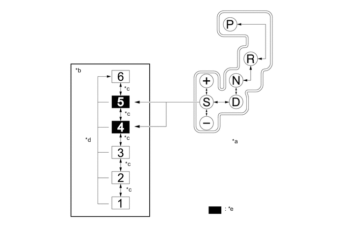
*a Shift Pattern *b Transition of Shift Range Position *c Moves Shift Lever to "+" (Forwards) or "-" (Backwards). *d Holding Shift Lever to "+" (Forwards). *e Default Shift Range - - Usable Gear Chart Shift Range Shift Range Indicator Display Usable Gear S6 6 6th←→5th←→4th←→3rd←→2nd←→1st S5 5 5th←→4th←→3rd←→2nd←→1st S4 4 4th←→3rd←→2nd←→1st S3 3 3rd←→2nd←→1st S2 2 2nd←→1st S1 1 1st -
When the shift lever is in S, the S mode indicator is shown in the combination meter assembly. The shift range indicator indicates the state of the shift range position that the driver has selected.
-
When the vehicle is being driven at a prescribed speed or higher, any attempt to shift to a lower range by operating the shift lever will not be executed, in order to protect the automatic transmission. In this case, the ECM sounds the multi buzzer in the combination meter assembly twice to alert the driver.
-
-
-
FUNCTION
-
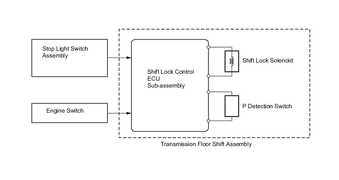
Shift Lock System
-
The shift lock system prevents the shift lever from being moved to any position other than P, unless the engine switch is turned on (IG) and the brake pedal is depressed. This prevents the vehicle from starting off suddenly.
-
The shift lock system is controlled by the shift lock control ECU sub-assembly, and it has a shift lock function.
-
The shift lock control ECU sub-assembly uses the P detection switch to detect the shift lever position, and receives input signals from the stop light switch assembly and engine switch. Upon receiving these signals, the shift lock control ECU sub-assembly turns on the shift lock solenoid in order to release the shift lock.
-
A shift lock release button, which manually overrides the shift lock mechanism, is used.
-
-
Shift Pattern Select System
-
The shift pattern select system enables the driver to use a multi-information switch to select the 2nd start mode which allows the vehicle to start off in the 2nd gear, thus making it easy for the vehicle to start off on snowy, sandy or muddy terrain.
-
When the 2nd start mode is selected while the shift lever is in D or in the S6, S5, S4, S3, or S2 range, the vehicle can start in the 2nd gear. After a start, if the shift lever is in D or in the S6, S5, S4, or S3 range, transmission will shift up automatically into 3rd, 4th, 5th or overdrive gears in the normal manner. If the shift lever is in the S2 range, the transmission will continue to operate in the 2nd gear.
-
The 2nd start mode cannot be selected while multi-terrain select is operating.*
-
*: Models with multi-terrain select
-
-
-
-
FAIL-SAFE
-
The fail-safe function minimizes the loss of operability when an abnormality occurs in a sensor or a shift solenoid valve.
Fail-safe Control List Malfunction Part Function Transmission Revolution Sensor (NT)
-
During a transmission revolution sensor (NT) malfunction, shift control is effected based on the transmission revolution sensor (SP2) signal.
-
During a transmission revolution sensor (NT) malfunction, upshifting to 5th and 6th, AI-shift control and flex lock-up clutch control are prohibited.
Transmission Revolution Sensor (SP2)
-
During a transmission revolution sensor (SP2) malfunction, shift control is effected based on the transmission revolution sensor (NT) signal.
-
During a transmission revolution sensor (SP2) malfunction, upshifting to 5th and 6th, AI-shift control and flex lock-up clutch control are prohibited.
No. 1 ATF Temperature Sensor (THO1) During a No. 1 ATF temperature sensor malfunction, upshifting to 5th and 6th, and flex lock-up clutch control are prohibited. Shift Solenoid Valves S1, S2, S3, S4 and SR
-
When one of the shift solenoid valves listed left malfunctions, current to the failed shift solenoid valve is cut off.
-
Shift control is changed to a fail-safe mode to shift gears using the normal shift solenoid valves to allow continued driving.
Shift Solenoid Valves SL1 and SL2 During a shift solenoid valve SL1 or SL2 malfunction, upshifting to 5th and 6th, and flex lock-up clutch control are prohibited. Line Pressure Control Solenoid Assembly (SLT) During a line pressure control solenoid assembly (SLT) malfunction, the current to the shift solenoid valve is stopped. Because this stops line pressure optimal control, the shift shock will increase. However, shifting is effected based on normal clutch pressure control. Lock-up Control Solenoid Assembly (SLU) During a lock-up control solenoid assembly (SLU) malfunction, the current to the shift solenoid valve is stopped. Because this stops lock-up timing control and flex lock-up clutch control, fuel economy decreases. -
-
-
DIAGNOSIS
-
When the ECM detects a malfunction, it makes a diagnosis and memorizes the failed section. Furthermore, the ECM illuminates or blinks the MIL in the combination meter assembly to inform the driver.*
-
*: Except models for G.C.C. countries
-
-
The ECM will also store the Diagnostic Trouble Codes (DTCs) of the malfunctions.
-
The DTCs can be read by connecting the intelligent tester II to the DLC3.
-
For details, refer to the Repair Manual.
-