ENGINE UNIT
-
CONSTRUCTION
-
The cylinder block is made of aluminum alloy.
-
The cylinder block has a bank angle of 90°, a bank offset of 21 mm (0.827 in.) and a bore pitch of 105.5 mm (4.15 in.), resulting in a compact block in its length and width considering its displacement.
-
Installation bosses of the 4 knock control sensors are located on the inner side of the left and right banks to enhance the accuracy of the knock control sensors.
-
An engine coolant distribution pathway is provided between the left and right banks. The engine coolant sent by the water pump passes through the engine coolant distribution pathway and flows to the cylinder head and water jackets of both banks. The engine coolant distribution pathway also cools the engine oil in the main oil hole located directly below the pathway.
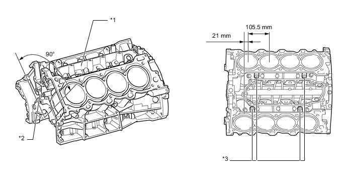
*1 Engine Coolant Distribution Pathway *2 Main Oil Hole *3 Knock Control Sensor Boss - - -
Air passage holes are provided on the bulkheads of the cylinder block. As a result, the air at the bottom of the cylinder flows smoother, and pumping loss (back pressure at the bottom of the piston generated by the piston's reciprocating movement) is reduced to improve the engine's output.
-
An engine coolant distribution pathway is provided between the left and right banks. The engine coolant sent by the water pump passes through the engine coolant distribution pathway and flows to the cylinder head and water jackets of both banks. The engine coolant distribution pathway also cools the engine oil in the main oil hole located directly below the pathway.
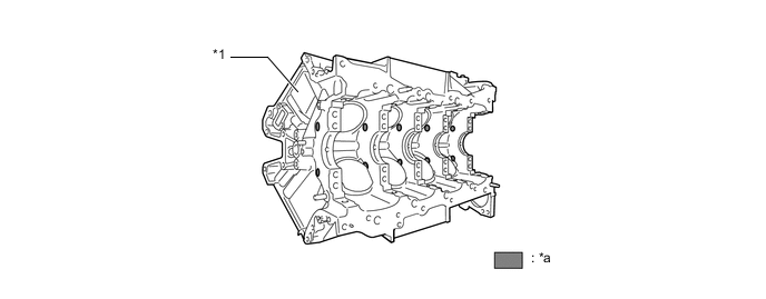
*1 Cylinder Block - - *a Air Passage Hole - - -
A water passage is provided between the cylinder bores. By allowing the engine coolant to flow between the cylinder bores, this construction keeps the temperature of the cylinder walls uniform.
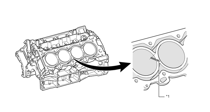
*1 Water Passage - - -
Spiny-type liners are used.
-
The liners are the spiny-type which have been manufactured so that their casting exteriors form large irregular surfaces in order to enhance the adhesion between the liners and the aluminum cylinder block. The enhanced adhesion helps heat dissipation, resulting in a lower overall temperature and heat deformation of the cylinder bores.
-
The shape of the cross-hatching of the liner surface has been optimized to improve oil retention performance, resulting in reduced friction.
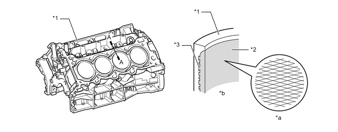
*1 Cylinder Block *2 Liner *3 Irregularly Shaped Outer Casting Surface of Liner - - *a Enlarged View of Cross-hatching *b A - A Cross Section -
Plastic cylinder block water jacket spacers are inserted in the water jacket. They control the flow of the engine coolant in order to attain a uniform temperature around the combustion chambers.
-
The temperature in the intake side of the cylinder bore tends to be lower. For this reason, a wide cylinder block water jacket spacer covers the cylinder bores in order to suppress the flow of the engine coolant and prevent excessive cooling. On the other hand, the temperature of the exhaust side of the cylinder bore tends to be higher. A cylinder block water jacket spacer covers the lower area of the cylinder bores in order to direct the engine coolant to the upper area of the cylinder bores where the temperature is higher. This makes the temperature around the cylinder bores more uniform. As a result, the viscosity of the engine oil (which lubricates the area between the wall surface of the cylinder bore and the piston) decreases, thus reducing friction between the cylinder bore and the piston.
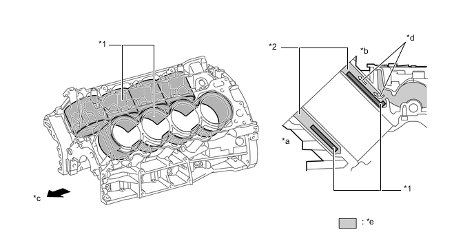
*1 Cylinder Block Water Jacket Spacer *2 Water Jacket *a Exhaust Side *b Intake Side *c Engine Front *d Engine Coolant Flow *e Engine Coolant - -
-