AIR CONDITIONING SYSTEM DETAILS
-
FUNCTION OF MAIN COMPONENTS
-
The automatic air conditioning consists of the following parts:
Component Function Air Conditioning Control Assembly Allows operation and adjustment of the air conditioning system via switches. Air Conditioning Amplifier Assembly Transmits and receives data to and from the switches and sensors. Electric Inverter Compressor Performs suction, compression and discharge of refrigerant gas and is driven by the electric motor. Blower with Fan Motor Sub-assembly High magnetic force magnets and ball bearings are used to achieve a compact and lightweight assembly. W/receiver Condenser Assembly A Multi-Flow-IV (MF-IV) sub-cool condenser is used to improve heat exchange efficiency. Heater Radiator Unit Sub-assembly A Straight Flow Aluminum-II (SFA-II) heater radiator is used for compactness and high performance. Cooler Expansion Valve Sprays the refrigerant in an atomized form. Cooler Evaporator Sub-assembly An Ejector Cycle System (ECS) cooler evaporator sub-assembly is used for compactness and high performance. Evaporator Temperature Sensor Detects the temperature of the cool air past the cooler evaporator sub-assembly and transmits the data to the air conditioning amplifier assembly. Ambient Temperature Sensor Detects ambient temperature and outputs it to the air conditioning amplifier assembly. Room Temperature Sensor Detects room temperature and outputs it to the air conditioning amplifier assembly. Automatic Light Control Sensor Detects the changes in the amount of solar energy and outputs them to the air conditioning amplifier assembly. PTC Heater * Consists of a Positive Temperature Coefficient (PTC) element, an aluminum fin, and a brass plate. Airmix Damper Servo Sub-assembly Operates the motor to open and close the driver side air mix damper upon receiving the input of the operation signals from the temperature setting dial via the air conditioning amplifier assembly, or when the system is operating under auto control. Recirculation Damper Servo Sub-assembly Receives the input of the operation signals from the fresh-air/recirculation selector switch via the air conditioning amplifier assembly, operates the motor, and opens and closes the fresh-air/ recirculation damper. Mode Damper Servo Sub-assembly Receives the input of the operation signals from the mode selector switch via the air conditioning amplifier assembly, operates the motor, and opens and closes the mode damper. Clean Air Filter Removes pollen and other particles to provide a comfortable interior space. Pressure Sensor Detects the refrigerant pressure and sends the data to the air conditioning amplifier assembly. ECM Receives the signals from the engine coolant temperature sensor and transmits them to the air conditioning amplifier assembly. Steering Pad Switch Assembly Sends the steering pad switch operation signal to the air conditioning control assembly. Eco Switch Sends the Eco switch operation signal to the air conditioning amplifier assembly.
-
*: Models with PTC heater
-
-
The solar ventilation system consists of the following parts:
Component Function Rear Glass Panel Generated by sunlight and supplies the power to the solar ECU and the blower with fan motor sub-assembly. Solar ECU Activated by power generated by the rear glass panel and controls the solar ventilation system. Ventilation Switch Turns the solar ventilation system on or off. Solar Relay Switches the power supply for the blower with fan motor sub-assembly from the auxiliary battery to the rear glass panel. Blower with Fan Motor Sub-assembly Driven by power generated by the rear glass panel and performs ventilation. Air Conditioning Amplifier Assembly Sends a drive signal to the mode damper servo sub-assembly and the recirculation damper servo sub-assembly. Mode Damper Servo Sub-assembly Drives the monitor based on signals from the air conditioning amplifier assembly and changes the air outlet mode to FACE. Recirculation Damper Servo Sub-assembly Drives the motor based on signals from the air conditioning amplifier assembly and changes the air inlet mode to FRESH. -
The remote air conditioning system consists of the following parts:
Component Function Wireless Remote Key Sends the remote air conditioning system ON and OFF signal to the certification ECU when the remote air conditioning switch is pressed. Certification ECU Receives the remote air conditioning system ON and OFF signals from the wireless remote key and sends them to the main ECU. Main Body ECU
-
Requests the power management ECU to supply power to each ECU and A/C inverter.
-
Sends the remote air conditioning mode signal to the power management control ECU, air conditioning amplifier assembly and certification ECU.
-
Requests the air conditioning system to drive or stop the air conditioning amplifier assembly.
Power Management Control ECU Performs the vehicle power supply control and the HV power supply control. Air Conditioning Amplifier Assembly Drives the blower with fan motor sub-assembly and the electric inverter compressor and controls the air conditioning system. -
-
-
OPERATING CONDITION
-
Solar Ventilation System
-
When all of the following conditions are met, the solar ECU activates the solar ventilation system.
-
The power switch is turned to off
-
The ventilation switch is turned to on.
-
Approximately 10 minutes or more have elapsed since the power switch was turned to off.
-
Both rear glass panel surface temperature and estimated amount of insolation, which has been calculated from the amount of power generated by the rear glass panel, exceed the predetermined values, respectively.
-
-
When one of the following operating conditions is not met, the ECU stops the operation of the solar ventilation system.
-
-
Remote Air Conditioning System
-
When all of the following conditions are met, the remote air conditioning system can be activated by operating the remote air conditioning switch on the wireless remote key.
ECU Condition Main Body ECU Power switch off All the doors and the engine hood are closed. Power switch is not pressed. Theft deterrent system is not armed. Locked when door lock signal is sent. Power Management Control ECU Shift position is in P. HV battery remaining amount is specified value or more. Air Conditioning Amplifier Assembly The air outlet mode changes to FACE mode according to the calculation based on the set temperature at the time of getting out of the vehicle. -
When any of the following conditions is met according to the items determined by each of the ECUs, the corresponding ECU stops the operation of the remote air conditioning system.
ECU Condition Main Body ECU When the operating conditions of the remote air conditioning system are not met. Power Management Control ECU Approximately 3 minutes have elapsed since the remote air conditioning system was operated. Certification ECU When the remote air conditioning operation is stopped using the remote air conditioning switch.
-
-
-
SYSTEM CONTROL
-
Control List
-
The air conditioning system uses the following types of control.
Control Outline Neural Network Control This control is capable of effecting complex control by artificially simulating the information processing method of the nervous system of living organisms in order to establish a complex input or output relationship that is similar to a human brain. Outlet Air Temperature Control In compliance with the temperature set at the temperature control switch, the neural network control calculates the outlet temperature based on the input signals from various sensors. In addition, corrections in accordance with the signals from the evaporative temperature sensor and water temperature sensor are added to control the outlet air temperature. Blower Control Controls the blower with fan motor sub-assembly in accordance with the airflow volume that has been calculated by the neural network control based on the input signals from various sensors. Air Outlet Control Automatically switches the outlets in accordance with the outlet mode ratio that has been calculated by the neural network control based on the input signals from various sensors. Micro Dust and Pollen Filter Mode Control Activated by the micro dust and pollen filter mode switch operation. Switches the air vent to the FACE mode. Sends air which has passed through the clean air filter to the area around the upper part of the bodies of the driver and front passenger. This air is filtered by the clean air filter in order to remove pollen. Air Inlet Control Automatically controls the air inlet control damper in accordance with the outlet temperature that has been calculated by the neural network control. Electric Inverter Compressor Control Compressor Speed Control The air conditioning amplifier assembly calculates the target speed of the compressor based on the target evaporator temperature (which is calculated by the temperature control switch, room temperature sensor, ambient temperature sensor, and automatic light control sensor) and the actual evaporator temperature that is detected by the evaporator temperature sensor in order to control the compressor speed. The air conditioning amplifier assembly calculates the target evaporator temperature, which includes corrections based on the temperature control switch, room temperature sensor, ambient temperature sensor, automatic light control sensor, and evaporator temperature sensor. Accordingly, the air conditioning amplifier assembly controls the compressor speed to an extent that would not inhibit the proper cooling performance or defogging performance. PTC Heater Control*1
-
When the hybrid system is operating (READY), and the blower with fan motor sub-assembly is turned on, the air conditioning amplifier assembly turns on the PTC heater if the conditions listed below are met.
-
Engine coolant temperature is below specified temperature.
-
Outside temperature is below specified temperature
-
Tentative air mix damper opening angle is above the specified value (MAX HOT).
Electric Water Pump Control The air conditioning amplifier assembly calculates the flow rate value required for the electric water pump in accordance with the engine coolant temperature and air mix damper opening degree and sends it to the ECM. ECO Drive Mode Control When the ECO switch is turned ON, the air conditioning amplifier assembly limits the air conditioning system performance. Rear Window Defogger & Mirror Heater Control When the power switch is turned to ON (IG), and the rear window defogger switch is pushed, this system is activated to keep the defogger heater on for approximately 15 minutes. Solar Ventilation System Control*2 The air conditioning amplifier assembly drives each servo motor when it receives the ventilation switch control signal from the solar ECU. Remote Air Conditioning System Control*2 The air conditioning amplifier assembly drives the air conditioning system when it receives the remote air conditioning mode signal through the power management control ECU via CAN communication from the main body ECU.
-
*1: Models with PTC heater
-
*2: Models with solar ventilation system and remote air conditioning system
-
-
-
Neural Network Control
-
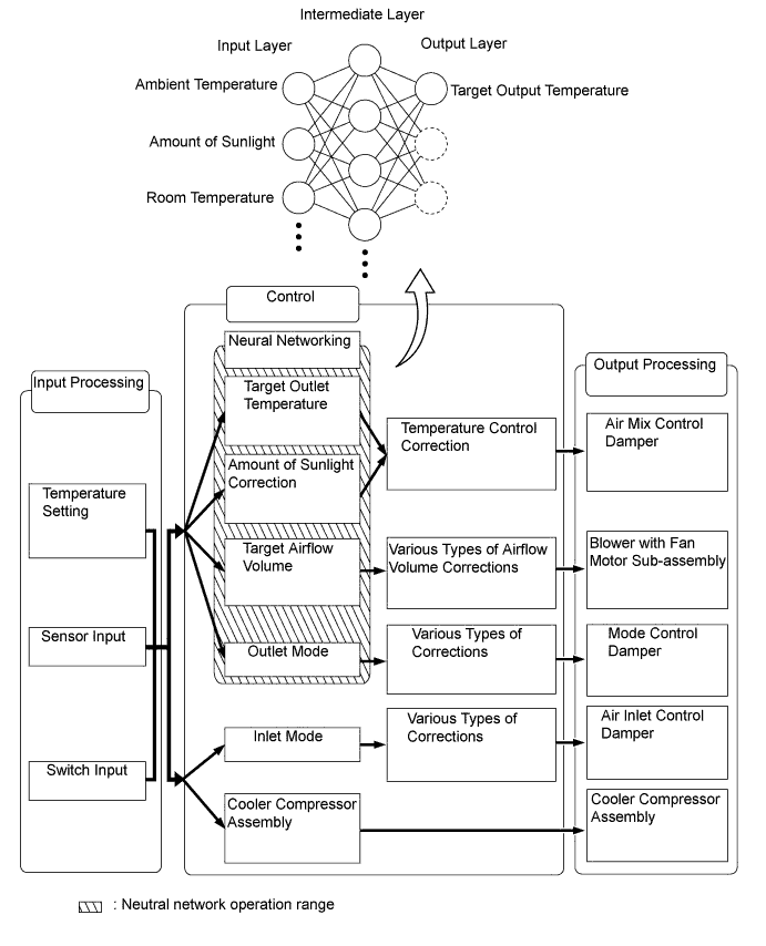
Previously, in automatic air conditioning systems without neural network control, the air conditioning amplifier determined the required outlet air temperature and blower air volume in accordance with the calculation formula that has been obtained based on information received from the sensors. However, because the senses of a person are rather complex, a given temperature is sensed differently, depending on the environment in which the person is situated. For example, a given amount of solar radiation can feel comfortably warm in a cold climate, or extremely uncomfortable in a hot climate. Therefore, as a technique for effecting a higher level of control, a neural network has been adopted in the automatic air conditioning system. With this technique, the data that has been collected under varying environmental conditions is stored in the air conditioning amplifier. The air conditioning amplifier can then effect control to provide enhanced air conditioning comfort.
-
The neural network control consists of neurons in the input layer, intermediate layer, and output layer. The input layer neurons process the input data of the ambient temperature, the amount of sunlight, and the room temperature based on the outputs of the switches and sensors, and output them to the intermediate layer neurons. Based on this data, the intermediate layer neurons adjust the strength of the links among the neurons. The sum of these is then calculated by the output layer neurons in the form of the required outlet temperature, solar correction, target airflow volume, and outlet mode control volume. Accordingly, the air conditioning amplifier controls the servo motors and blower with fan motor sub-assembly in accordance with the control volumes that have been calculated by the neural network control.
-
-
Electric Inverter Compressor Control
-
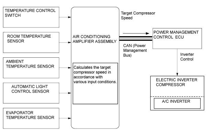
The air conditioning amplifier assembly calculates the target compressor speed based on the target evaporator temperature (calculated from the temperature control switch, room temperature sensor, ambient temperature sensor, and automatic light control sensor) and the actual evaporator temperature detected by the evaporator temperature sensor. Then, the air conditioning amplifier assembly transmits the target speed to the power management control ECU. The power management control ECU controls the A/C inverter based on the target speed data in order to control the electric inverter compressor to a speed that suits the operating condition of the air conditioning system.
-
The air conditioning amplifier assembly calculates the target evaporator temperature, which includes corrections based on the temperature control switch, room temperature sensor, ambient temperature sensor, automatic light control sensor, and evaporator temperature sensor. Accordingly, the air conditioning amplifier assembly controls the compressor speed to an extent that does not inhibit the proper cooling performance or defogging performance. As a result, comfort and low fuel consumption can be realized.
-
The electric inverter compressor uses high-voltage alternating current. If a short or open circuit occurs in the electric inverter compressor wiring harness, the power management control ECU will cut off the A/C inverter circuit in order to stop the power supply to the compressor motor.
-
-
Eco Drive Mode Control
-
Under the control of the eco drive mode, the air conditioning amplifier assembly restricts the air conditioning system performance under specified conditions, thus improving fuel economy.
-
The eco drive mode control is activated when the eco drive mode switch provided inside the integration control panel is pressed, and then restricts the air conditioning system performance as described below.
Control Outline Inside/outside Air Switch Control Automatically switches the air inlet port to the internal air circulation mode when the outside air temperature is equal to or higher than a predetermined temperature and reduces the power consumption. Blower Level Control Sets the blower level in AUTO mode lower than normal, and suppresses the power consumption. PTC Heater Control Stops the operation of PTC heater and suppresses the power consumption. Heating Restriction Control Changes the air outlet temperature by turning the eco drive mode switch on and off during heating and increases the amount of engine-off time when the eco drive mode switch is in the on state, thus improving fuel economy. Compressor Speed Restriction Control Restricts the maximum speed during cooling and reduces the power consumption.
-
-
Micro Dust and Pollen Filter Mode Control
-
When the micro dust and pollen filter switch is pressed, the micro dust and pollen filter control is activated.
-
Then, the air vent is switched to the FACE mode and recirculated pollen-free air flows in the area around the upper part of the bodies of the driver and front passenger.
-
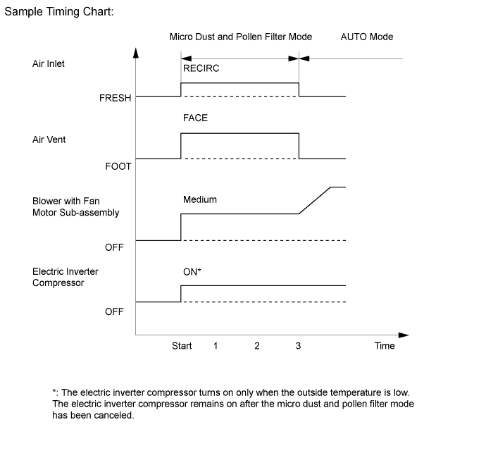
When the micro dust and pollen filter switch signal is input to the air conditioning amplifier assembly, the air conditioning amplifier assembly controls the electric inverter compressor, air inlet servomotor, air vent servomotor and blower with fan motor sub-assembly as shown in the timing chart below.
-
This control usually operates for approximately 3 minutes. However, when the outside temperature is low [5°C (41°F) maximum], it will operate for approximately 1 minute.
-
After this control stops operating, the air conditioning amplifier assembly controls the air conditioning system using the AUTO mode.
-
-
Solar Ventilation System Control
-
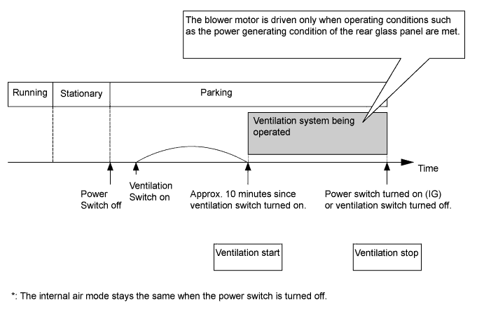
If the ventilation switch is turned on when the power switch is turned to ON (IG):
-
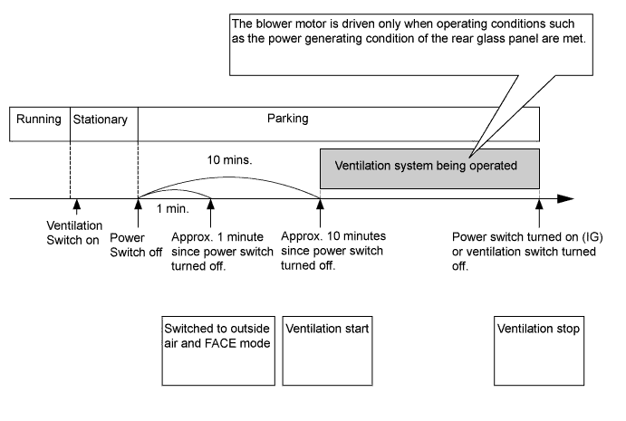
In order to provide more efficient ventilation, the air conditioning amplifier assembly switches the air inlet port to the FRESH mode and the air outlet port to the FACE mode after approximately 1 minute has passed since the power switch was turned off.
-
In order to prevent cold air in the cabin escaping outside immediately after the engine is stopped, the solar ECU activates the blower motor to start ventilation after approximately 10 minutes have passed since the power switch was turned off.
-
-
If the ventilation switch is turned on when the power switch is turned to off:
-
The air inlet and outlet modes remain the same and the solar ECU starts ventilation approximately 10 minutes after the ventilation switch is turned on.
Tech Tips
If the solar ventilation system is used because the ventilating effect cannot be obtained sufficiently in the internal air mode, turn on the ventilation switch when the power switch is turned to on (IG).
-
-
-
Remote Air Conditioning System Control
-
The remote air conditioning system can be activated by pressing and holding the remote air conditioning switch on the wireless key once (for approximately 1 second or more). At this time, the wireless door lock will also be activated, thus improving anti-theft performance.
-
The remote air conditioning system can be deactivated by pushing the remote air conditioning switch on the wireless key twice briefly (for approximately less than 3 seconds) while the remote air conditioning system is in operation. At this time, the wireless door lock buzzer will sound twice as an answer back on Australian models only.
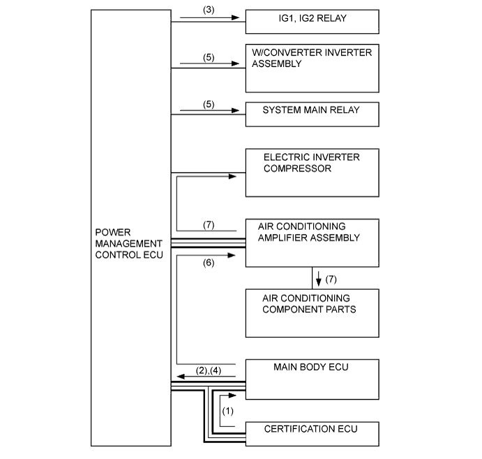
Step System Operation (1) Sends the remote control system activation signal from the remote air conditioning switch on the wireless key to the main body ECU via the certification ECU. (2) The main body ECU checks the operating condition and sends the remote air conditioning on request signal to the power management control ECU. (3) The power management control ECU turns the IG1 and IG2 relays on according to the remote air conditioning on request signal. (4) The main body ECU sends the HV system starting request signal to the power management control ECU. (5) The power management control ECU checks the operating condition, turns on the system main relay and then operates the w/converter Inverter assembly. (6) The main body ECU sends the remote air conditioning mode signal to the air conditioning amplifier assembly. (7) The air conditioning amplifier assembly checks the operating condition, drives the electric inverter compressor and the blower with fan motor sub-assembly and then activates the auto air conditioning system.
-
-
-
FUNCTION
-
Solar Ventilation System and Remote Air Conditioning System
-
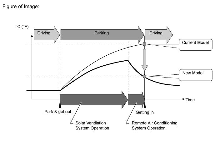
The following graph illustrates the system effects when a vehicle is parked under hot weather conditions for a long time:
-
The solar ventilation system is activated after the vehicle is parked and discharges high temperature air to suppress any increase in the vehicle interior temperature.
-
The remote air conditioning system is activated immediately before getting into the vehicle and reduces the vehicle interior temperature.
-
Thus, even if the cabin temperature rises high, the temperature can be significantly lowered before getting in, and the solar ventilation system and remote air conditioning system offer a more comfortable vehicle interior space, compared to the current models.
-
-
-
-
CONSTRUCTION
-
Air Conditioning Control Assembly
-
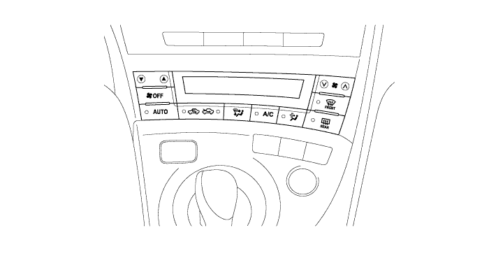
A push button type air conditioning control assembly is used.
-
This air conditioning control assembly uses an LCD (Liquid Crystal Display) to display the set temperature, air outlet mode and blower speed to ensure excellent visibility.
-
-
Air Conditioning Radiator Assembly
-
A semi-center location air conditioner unit in which the cooler evaporator sub-assembly and heater radiator unit sub-assembly are placed in the vehicle's longitudinal direction is used.
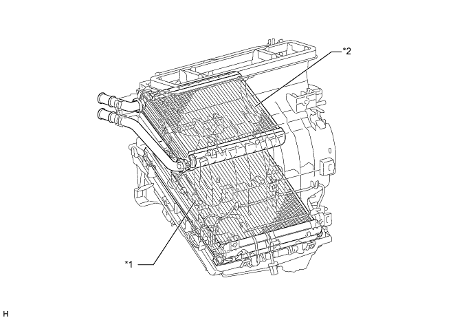
Text in Illustration *1 Cooler Evaporator Sub-assembly *2 Heater Radiator Unit Sub-assembly -
The partial recirculation system is used. This system has an air inlet control door (sub) in the cabin side of the air inlet duct. Thus, it is able to cycle a small volume of recirculated air even in the FRESH mode, thus ensuring heating and air conditioning performance. When the blower switch is on, the suction force of the blower fan opens this air inlet control door (sub).
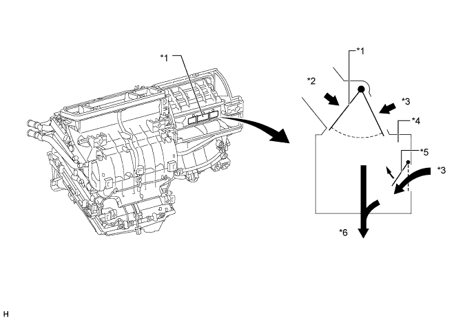
Text in Illustration *1 Air Inlet Control Door *2 Fresh *3 Recirculation *4 Air Inlet Duct *5 Air Inlet Control Door (sub) *6 To Blower Fan
-
-
Cooler Evaporator Sub-assembly
-
The Ejector Cycle System (ECS) type cooler evaporator sub-assembly is used.
-
By placing the tanks at the top and the bottom of the evaporator unit and adopting a micropore tube construction, the following effects have been realized:
-
The heat exchanging efficiency has been improved.
-
The temperature distribution has been made more uniform.
-
The evaporator has been made thinner.
-
-
The ejector is provided in the top tank of the cooler evaporator sub-assembly.
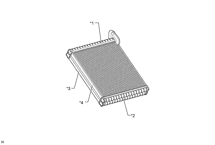
Text in Illustration *1 Top Tank (Built into the ejector) *2 Bottom Tank *3 Upwind Side *4 Downwind Side
-
-
Evaporator Temperature Sensor
-
The evaporator temperature sensor detects the temperature of the cool air immediately past the cooler evaporator sub-assembly in the form of resistance changes, and outputs it to the air conditioning amplifier assembly.
-
-
Blower with Fan Motor Sub-assembly
-
The blower with fan motor sub-assembly has an in-built blower controller, and is controlled with the duty control from the air conditioning amplifier assembly.
-
In consideration of a reduction in the service life of the motor due to wear, a brushless type blower with fan motor sub-assembly is used on models equipped with the solar ventilation system and the remote air conditioning system. The motor shaft uses the ball bearing, enabling long time operation under high temperature conditions.
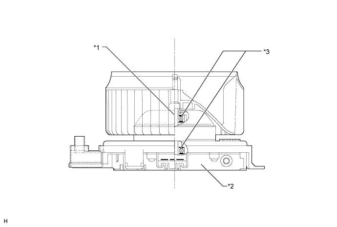
Text in Illustration (Brushless type Blower with Fan Motor Sub-assembly:) *1 Blower Motor *2 Blower Controller *3 Ball Bearing - -
-
-
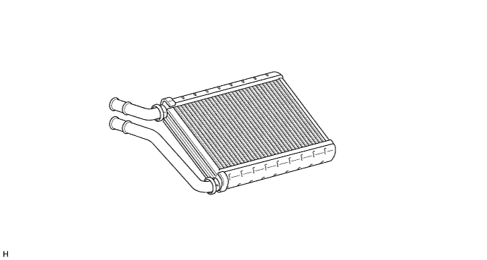
Heater Radiator Unit Sub-assembly
-
This heater radiator unit sub-assembly has been made more compact and higher performance by making the core section finer and improving the shapes of the tank section and flow section. Also, the environment is considered. By using aluminum as the material, the amount of the environmental burden disposal (lead) is reduced.
-
-
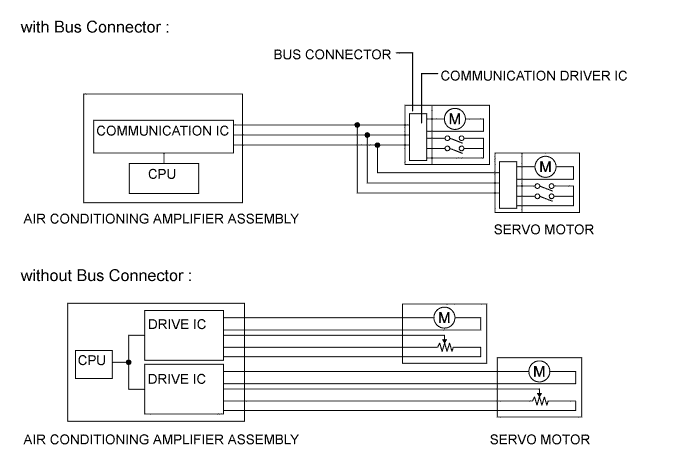
Bus Connector
-
The Bus connector is used in the wire harness connection that connects the servo motor from the air conditioning amplifier assembly.
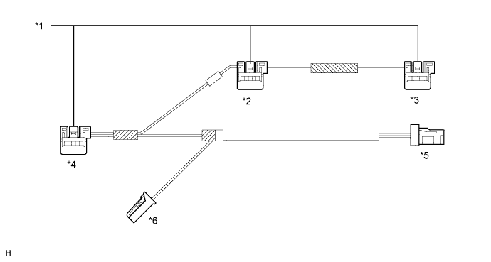
Text in Illustration *1 Bus Connector *2 To Mode Control Servo Motor *3 To Air Inlet Control Servo Motor *4 To Air Mix Control Servo Motor *5 To Air Conditioning Amplifier Assembly *6 To Evaporator Temperature Sensor -
The Bus connector has a built-in driver IC which communicates with each servo motor connector, actuates the servo motor, and has a position detection function. This enables bus communication for the servo motor wire harness, for a more lightweight construction and a reduced number of wires.
-
-
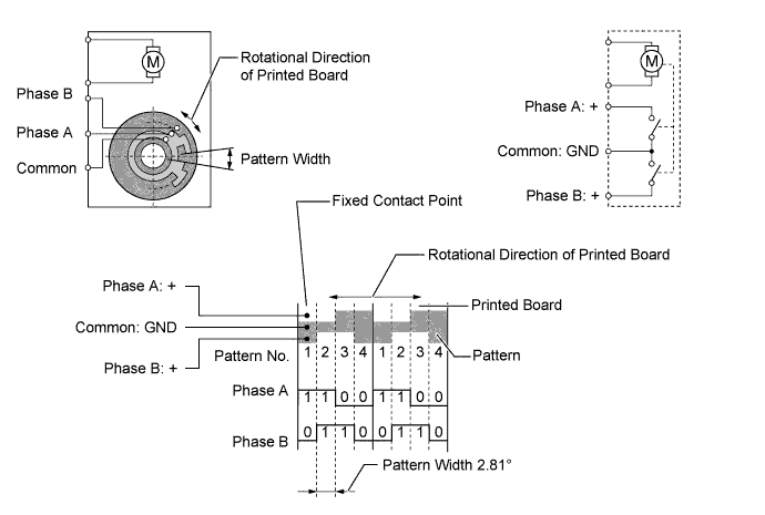
Servo Motor
-
In contrast to the previous type that detects the position by way of a potentiometer voltage, the pulse pattern type servomotor detects the relative position by way of the 2-bit on/off signals.
-
The forward and reverse revolutions of this motor are detected by way of two phases, A and B, which output four types of patterns. The air conditioning amplifier assembly counts the number of pulse patterns in order to determine the stopped position.
-
-
PTC Heater
-
The PTC (Positive Temperature Coefficient) heater is located above the heater radiator unit sub-assembly in the air conditioner unit.
-
The PTC heater consists of a PTC element, aluminum fin, and brass plate. When current is applied to the PTC element, it generates heat to warm the air that passes through the unit.
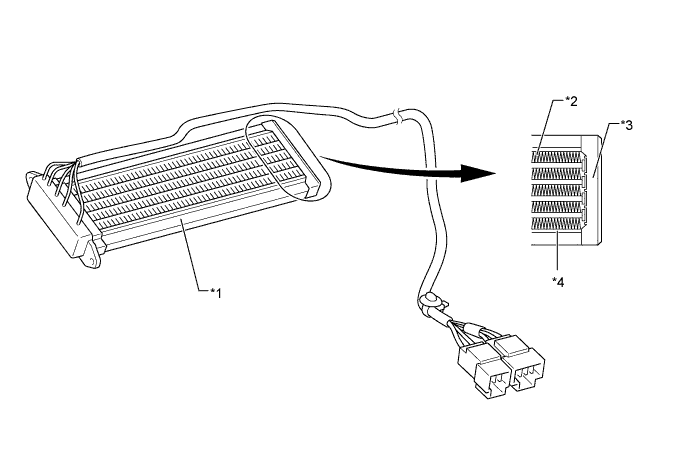
Text in Illustration *1 PTC Heater *2 Aluminum Fin *3 Brass Plate *4 PTC Element
-
-
Clean Air Filter
-
A pollen removal type clean air filter is used to remove dust, pollen, and other micron particles from air entering from outside the vehicle to provide a comfortable cabin of clean air. The clean air filter is installed in the upper section of the blower fan for easy replacement of the clean air filter without the need for tools by removing the one-touch clip in the glove box, making this easy to service.
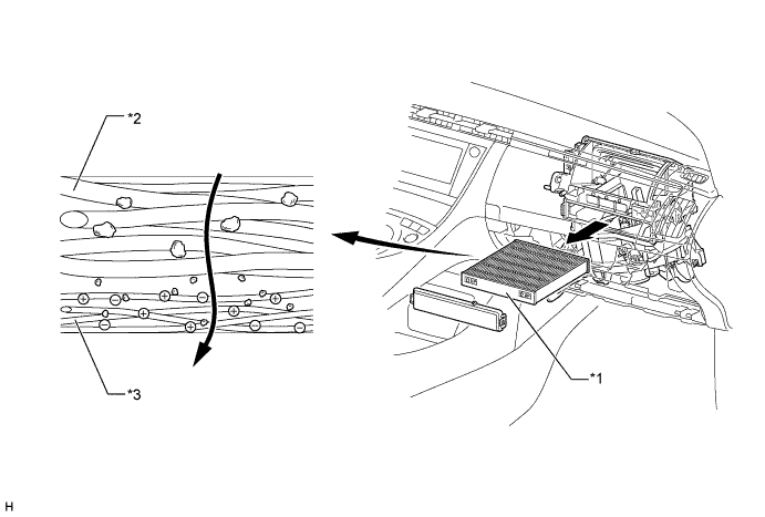
Text in Illustration *1 Clean Air Filter *2 Large Foreign Object Filter Layer *3 Electret Layer (Microscopic foreign object) - - Tech Tips
The following table describes the usage conditions and cleaning and replacement intervals for models equipped with the solar ventilation system. However, the observation of these guidelines should depend on the usage conditions (or environment).
Destination Usage Conditions and Solar Ventilation System Setting Cleaning Interval Replacement Interval Europe models Normal condition 15000 km (9000mile) 30000 km (18000mile) Dusty road conditions or models equipped with solar ventilation system 7500 km (4500mile) 15000 km (9000mile) Australia model Normal condition 15000 km (9000mile) 30000 km (18000mile) Dusty road conditions or models equipped with the solar ventilation 7500 km (4500mile) 15000 km (9000mile)
-
-
W/receiver Condenser Assembly
-
A MF (Multi-Flow) type w/receiver condenser assembly is used. The w/receiver condenser assembly consists of two cooling portions: a condensing portion and a super-cooling portion, and gas-liquid separator (modulator) are integrated together. This w/receiver condenser assembly uses a sub-cool cycle that offers excellent heat-exchange performance.
-
In the sub-cool cycle, after the refrigerant passes through the condensing portion of the w/receiver condenser assembly, both the liquid refrigerant and the gaseous refrigerant that could not be liquefied are cooled again in the super-cooling portion. Thus, the refrigerant is sent to the cooler evaporator sub-assembly in an almost completely liquefied state.
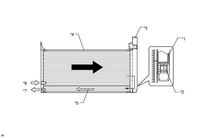
Text in Illustration *1 Desiccant *2 Filter *3 Modulator *4 Condensing Portion *5 Super-cooling Portion *6 Gaseous Refrigerant *7 Liquid Refrigerant - - Tech Tips
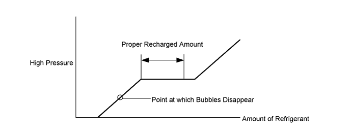
The point at which the air bubbles disappear in the refrigerant of the sub-cool cycle is lower than the proper amount of refrigerant with which the system must be filled. Therefore, if the system is recharged with refrigerant based on the point at which the air bubbles disappear, the amount of refrigerant would be insufficient. As a result, the cooling performance of the system would be affected. If the system is overcharged with refrigerant, this will also lead to reduced performance. For the proper method of verifying the amount of the refrigerant and for instructions on how to recharge the system with refrigerant, see the Repair Manual.
-
-
Electric Inverter Compressor
-
An ES14 type electric inverter compressor that is driven by a motor is used. The basic construction and operation of this compressor are the same as the ordinary scroll compressor, except that it is driven by an electric motor.
-
The compressor with motor assembly consists of a spirally wound fixed scroll and variable scroll that form a pair, a brushless motor, an oil separator, a motor shaft and A/C (Air Conditioning) inverter.
-
The A/C inverter is integrated with the compressor. This inverter operates the compressor on the HV battery. As a result, the air conditioning system is actuated without depending on the operation of the engine, thus realizing a comfortable air conditioning system and low fuel consumption.
-
The fixed scroll is integrated with the housing. Because the rotation of the shaft causes the variable scroll to revolve while maintaining the same posture, the volume of the space that is partitioned by both scrolls varies to perform the suction, compression, and the discharge of the refrigerant gas. Locating the suction port directly above the scrolls enables direct suction, thus realizing improved suction efficiency. Containing a built-in oil separator, this compressor is able to separate the compressor oil that is intermixed with the refrigerant and circulates in the refrigeration cycle, thus realizing a reduction in the oil circulation rate.
-
Low-moisture permeation hoses are used for the suction and discharge hoses at the compressor in order to minimize the entry of moisture into the refrigeration cycle.
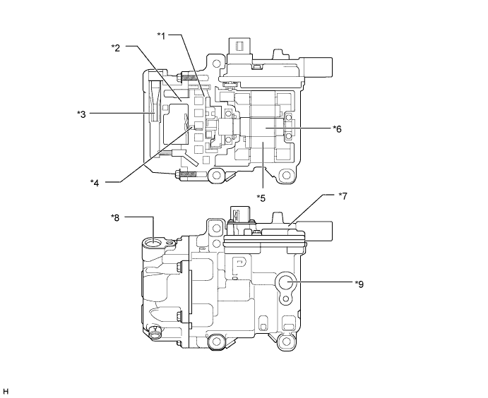
Text in Illustration *1 Variable Scroll *2 Fixed Scroll *3 Oil Separator *4 Discharge Port *5 Brushless Motor *6 Motor Shaft *7 A/C Inverter *8 Discharge Hose Port *9 Suction Hose Port - - CAUTION:
In order ensure the proper insulation of the internal high-voltage portion of the compressor and the compressor housing, the new Prius has adopted a compressor oil (ND11) with a high level of insulation performance. Therefore, never use a compressor oil other than the ND11 type compressor oil or its equivalent.
-
-
Room Temperature Sensor and Ambient Temperature Sensor
-
The room temperature sensor detects the room temperature based on changes in the resistance of its built-in thermistor and sends a signal to the air conditioning amplifier assembly.
-
The ambient temperature sensor detects the room temperature based on changes in the resistance of its built-in thermistor and sends a signal to the air conditioning amplifier assembly.
-
-
Automatic Light Control Sensor
-
The automatic light control sensor detects (in the form of changes in the current that flows through the built-in photo diode) the changes in the amount of sunlight and outputs these sunlight strength signals to the air conditioning amplifier assembly.
-
-
-
OPERATION
-
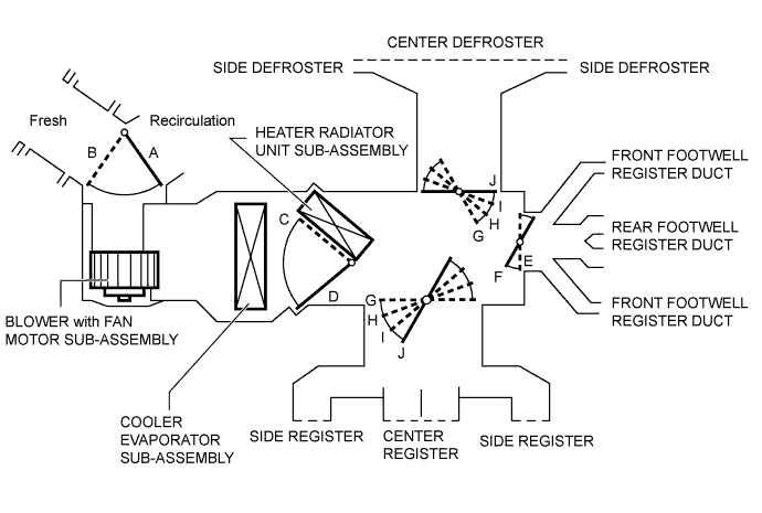
Mode Position and Door Operation
Tech Tips
This illustration is a model diagram showing the doors positions in each mode. The parts layout and the number of the doors in the illustration are different from those of the actual system.
Control Damper Operation Position Damper Position Operation Air Inlet Control Damper FRESH A Brings in fresh air. RECIRCULATION B Recirculates internal air. Air Mix Control Damper MAX COLD-MAX HOT C, D Varies the mixture ratio of the fresh air and the recirculation air in order to regulate the temperature continuously from HOT to COLD. Control Damper Operation Position Damper Position Operation Mode Control Damper 
FACE E, J Air blows out of the center register and side register. 
BI-LEVEL F, J Air blows out of the center register, side registers, and front and rear footwell register ducts. 
FOOT F, I Air blows out of the front and rear footwell register ducts and side register. In addition, air blows out slightly from the front defroster and side defroster. 
FOOT/DEF F, H Defrosts the windshield through the center defroster, side defroster and side register, while air is also blown out from the front and rear footwell register ducts. 
DEF E, G Defrosts the windshield through the center defroster, side defroster and side register. -
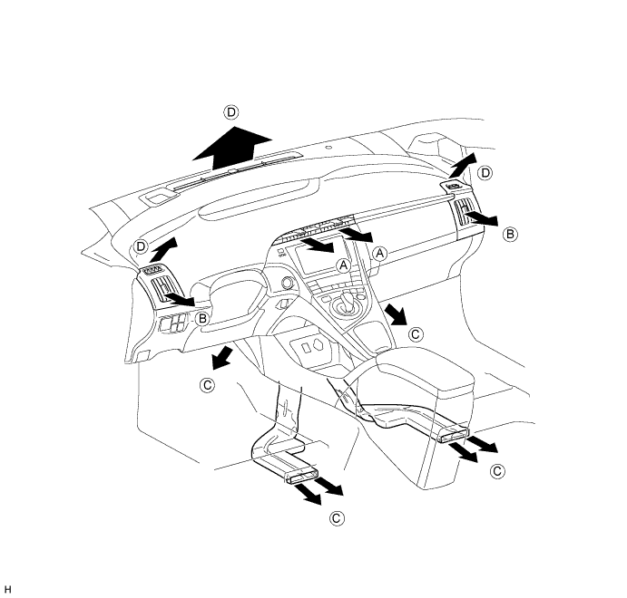
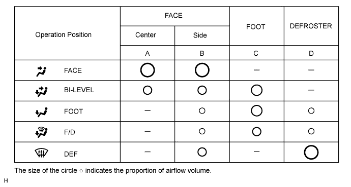
Air Outlets and Airflow Volume
-
Electric Inverter Compressor Operation
-
The electric inverter compressor performs suction, compression and discharge of refrigerant gas as described in the table below.
Stroke Operation Suction As the capacity of the compression chamber, which is created between the variable scroll and the fixed scroll, increases in accordance with the revolution of the variable scroll, refrigerant gas is drawn in from the intake port. Compression From the state at which the suction process has been completed, as the revolution of the variable scroll advances further, the capacity of the compression chamber decreases gradually. Consequently, the refrigerant gas that has been drawn in becomes compressed gradually and is sent to the center of the fixed scroll. The compression of the refrigerant gas is completed when the variable scroll completes approximately 2 revolutions. Discharge When the compression of the refrigerant gas is completed and the refrigerant pressure becomes high, the refrigerant gas discharges through the discharge port located in the center of the fixed scroll by pushing the discharge valve. 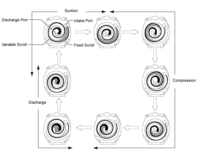
-
-
Ejector Cycle System Operation
-
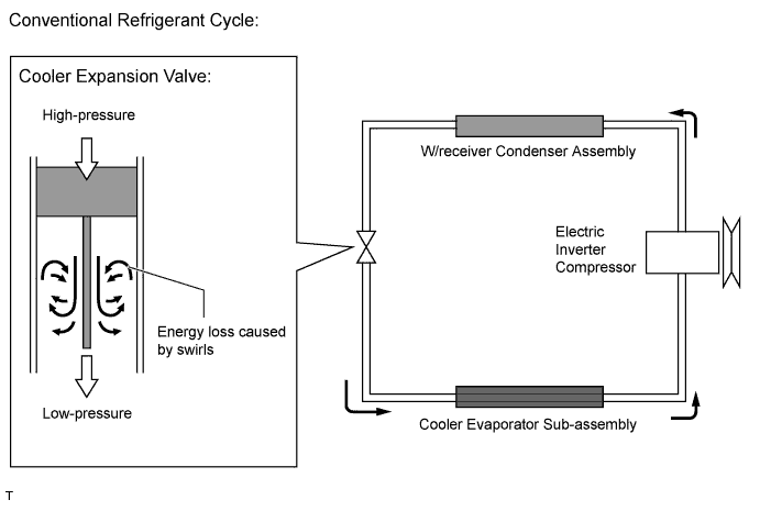
In the conventional refrigerant cycle, liquid refrigerant gas is sent into the cooler evaporator sub-assembly using the cooler expansion valve, generating cold air. However, a rapid decrease in the refrigerant pressure forms swirls, causing energy loss. In this ejector cycle, the energy loss caused by the cooler expansion valve is utilized by the operation of the ejector that injects and expands a high-pressure refrigerant, thus improving energy consumption efficiency.
-
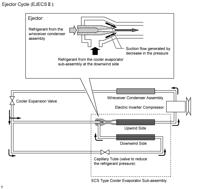
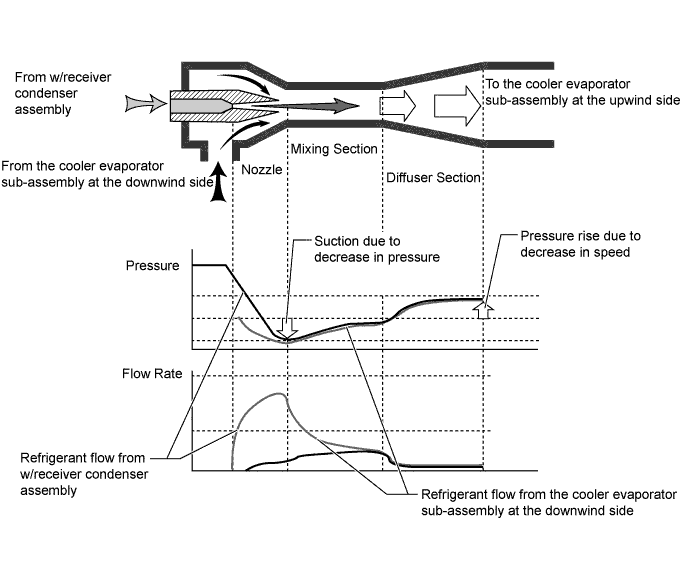
The ejector includes nozzle, mixing and diffuser portions.
-
A high temperature and pressure liquid refrigerant flowing from the w/receiver condenser assembly is introduced into the mixing section through the nozzle at high speeds as the nozzle is inwardly tapered. This decreases the refrigerant pressure in the vicinity of the nozzle, introducing low temperature and pressure gaseous refrigerant into the nozzle from the cooler evaporator sub-assembly. Thus, both refrigerants are mixed in the mixing section and are introduced into the diffuser section.
-
As the diffuser section is outwardly flared, the refrigerant flow rate in the diffuser decreases and the refrigerant pressure rises.
-
Through these operations, the refrigerant pressure in the cooler evaporator sub-assembly on the downwind side can be constantly kept lower than that on the upwind side, creating the lower temperature conditions. Therefore, air cooled by the cooler evaporator sub-assembly on the upwind side can be further cooled by that on the downwind side, thus improving the efficiency of the cooler evaporator sub-assembly.
-
-
-
DIAGNOSIS
-
The air conditioning amplifier assembly has a diagnosis function. It stores a record of any air conditioning system failures in memory in the form of Diagnostic Trouble Codes (DTCs).
-
There are two methods for reading DTCs. One is to use the intelligent tester and the other is to read the DTCs using the heater control panel display. For details, refer to the Repair Manual.
-