AIRBAG SYSTEM DETAILS
-
FUNCTION OF MAIN COMPONENTS
-
The SRS airbag system mainly consists of the parts listed in the table below.
Component Outline Airbag ECU Assembly
-
Detects the deceleration of the vehicle during a collision, determines whether ignition is necessary based on the signals from each airbag sensor, and transmits deployment signals to each airbag and seat belt pretensioner.
-
Provides initial check and diagnosis function.
Airbag Assembly Mainly consists of an inflator and a bag. Upon receiving a deployment signal from the airbag ECU assembly, the inflator generates gas to deploy the bag. Airbag Sensor Detects the deceleration of the vehicle during a collision, and transmits the signal to the airbag ECU assembly, from which the airbag ECU assembly determines whether ignition is necessary. Airbag Cut-off Switch Transmits on/off signals to the airbag ECU assembly to manually turn on or off the deployment of the front passenger side airbags. SRS Warning Light Provided in the combination meter assembly and comes on when the SRS airbag system malfunctions. -
-
-
OPERATING CONDITION
-
Ignition Condition
-
Deceleration sensors used for the airbag system are installed on various parts on the vehicle and calculate the deceleration rate of each part during a collision.
-
Depending on the situation, the airbag ECU assembly sends a deployment signal to each airbag based on the information from each sensor.
-
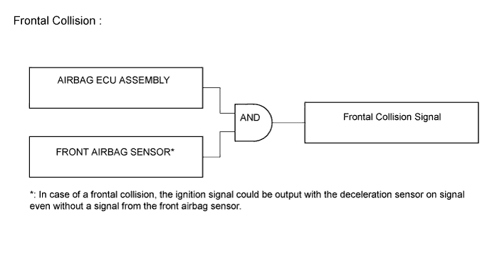
Frontal collision signals are produced based on the information from the airbag ECU assembly and front airbag sensors. Frontal collision signals are used to deploy the airbags except the side airbags and curtain shield airbags.
-
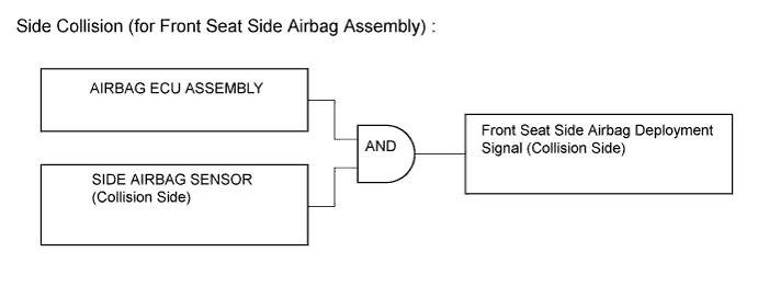
The side airbags are deployed based on signals from the side airbag sensors and airbag ECU assembly.
Tech Tips
The side curtain shield airbag is deployed at the same time.
-
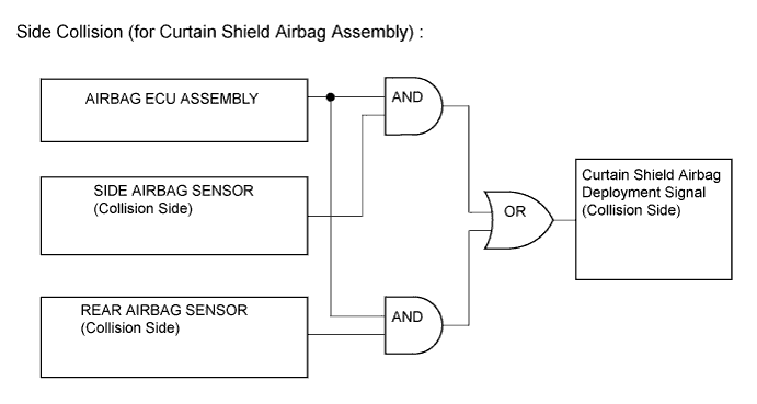
The curtain shield airbag is deployed based on signals from the side airbag sensors and airbag ECU assembly or the rear airbag sensor and airbag ECU assembly.
-
-
-
SYSTEM CONTROL
-
Airbag for Frontal Collision
-
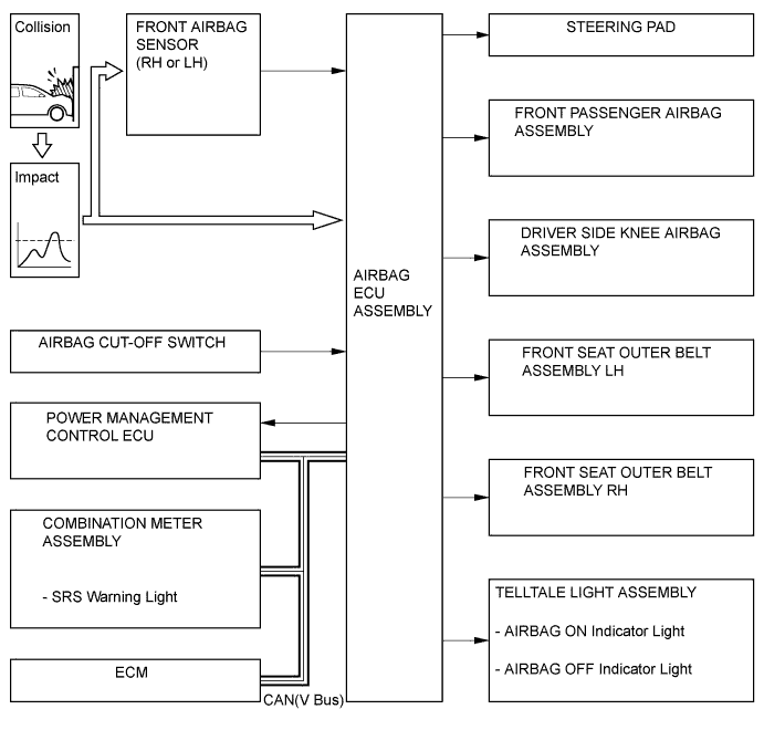
For frontal collisions, there are 3 airbags and 2 seat belt pretensioners: a steering pad, front passenger airbag assembly, driver side knee airbag assembly, front seat outer belt assembly LH, and front seat outer belt assembly RH. The deployment of the airbags and the activation of the pretensioners occur simultaneously.
-
-
Airbag for Side/Side Rear Collision
-
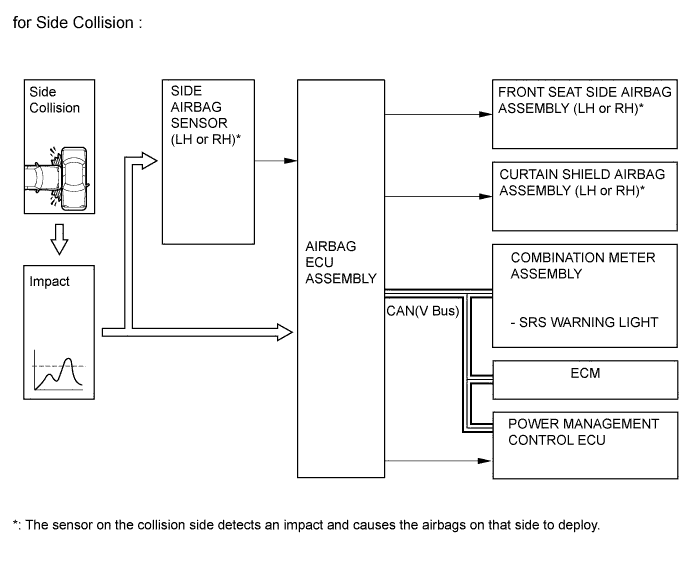
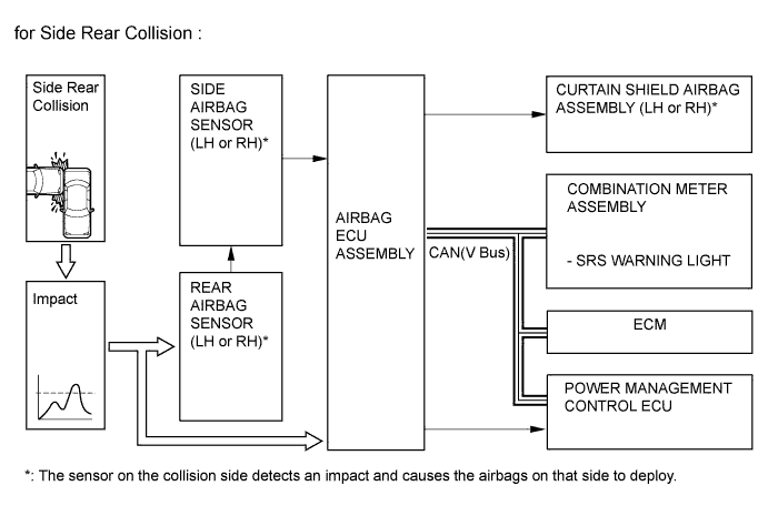
For severe side collisions there are 2 airbags: front seat side airbag assembly and curtain shield airbag assembly. These airbags deploy simultaneously. For severe side rear collisions only the curtain shield airbag assembly will deploy.
-
For a side collision, if the side airbag sensor detects an impact, it informs the airbag ECU assembly, and the airbag ECU assembly causes the front seat side and curtain shield airbag assemblies to be deployed simultaneously.
-
For a side rear collision, if the rear airbag sensor detects an impact, it informs the airbag ECU assembly via the side airbag sensor, and the airbag ECU assembly causes the curtain shield airbag assembly to be deployed.
-
-
Primary Check Illumination Control
-
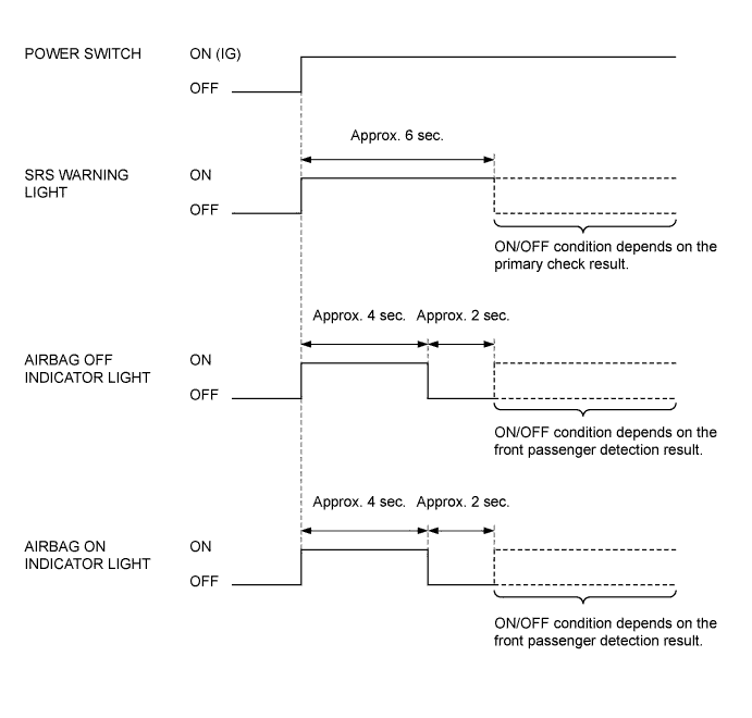
After the power switch is on(IG), the airbag ECU assembly illuminates the SRS warning light in the combination meter assembly for approximately 6 seconds and conducts the primary check. During the primary check, the ignition of airbags is prohibited and a diagnosis of the airbag ECU assembly is performed. If trouble is detected during the primary check, the SRS warning light remains on even after the 6 seconds have elapsed. See the illustration below.
-
After the power switch is on(IG), the airbag ECU assembly operates the AIRBAG on/ off indicator lights as shown below to check for an open in the airbag cut-off switch indicator circuit.
-
-
-
FUNCTION
-
Airbag Cut-off Switch
-
The deployment of the front passenger airbag assembly can be prohibited by operating the airbag cut-off switch located on the lower portion of the instrument panel on the driver side. When the airbag cut-off switch is turned to off , these airbags will not be deployed even if a collision occurs.
-
Turn the airbag cut-off switch on and off by inserting the key and turning it.
-
The AIRBAG on/off indicator lights, which inform the driver of the airbag cut-off switch status, have been provided in the telltale light assembly on the upper portion of the instrument panel.
-
The table below shows whether the airbags for the front passenger are enabled or disabled and the AIRBAG on/off indicator lights come on or go off depending on the airbag cut-off switch status.
Item Airbag Cut-off Switch Condition ON OFF Failure Front Passenger Airbag Assembly X - - Front Seat Side Airbag Assembly X X X Front Seat Outer Belt Assembly for Front Passenger X X X Curtain Shield Airbag Assembly for Front Passenger X X X AIRBAG ON Indicator Light X - - AIRBAG OFF Indicator Light - X X
-
○: Enabled (Light comes on)
-
X: Disabled (Light goes off)
-
-
-
-
CONSTRUCTION
-
Steering Pad and Front Passenger Airbag Assembly
-
The steering pad and front passenger airbag assembly mainly consists of an inflator and a bag.
-
-
Driver Side Knee Airbag Assembly
-
The driver side knee airbag assembly consists of an airbag door, an inflator, and a bag.
-
-
Curtain Shield Airbag Assembly
-
Curtain shield airbag assemblies that extend from the front pillar to the roof side rail are installed. Each curtain shield airbag assembly consists of an inflator, a bag, and a cover.
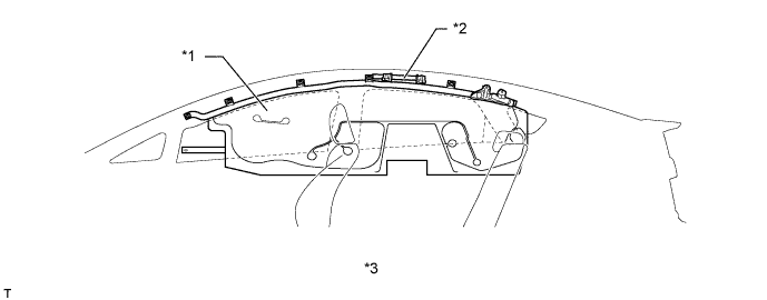
Text in Illustration *1 Bag *2 Inflator *3 Deployed Airbag - -
-
-
Front Seat Side Airbag Assembly
-
Front seat side airbag assemblies are installed in the seat backs of the driver seat and the front passenger seat. Each front seat side airbag assembly consists of an inflator, a bag, and a cover.
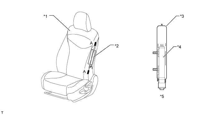
Text in Illustration *1 Front Seat Assembly *2 Front Seat Side Airbag Assembly *3 Cover *4 Inflator *5 A-A Cross Section - -
-
-
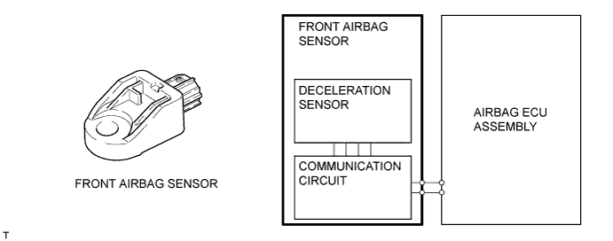
Front Airbag Sensor
-
Front airbag sensor uses an electrical type deceleration sensor. Based on the deceleration of the vehicle during a front collision, a distortion is created in the sensor and converted into an electrical signal. Accordingly, the extent of the initial collision can be detected in detail.
-
-
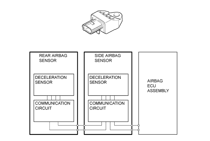
Side and Rear Airbag Sensors
-
A deceleration sensor is enclosed in the side airbag sensor and rear airbag sensor. Based on the deceleration of the vehicle during a side or side rear collision, a distortion is created in the sensor and converted into an electrical signal.
-
-
-
DIAGNOSIS
-
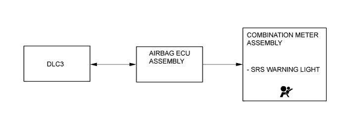
If the airbag ECU assembly detects a malfunction in the SRS airbag system, the airbag ECU assembly stores the malfunction data in memory, in addition to illuminating the SRS warning light.
-
There are 2 types of DTC (Diagnostic Trouble Code) for the SRS airbag system: 5-digit and 2-digit.
-
The 5-digit DTC can be read by connecting an intelligent tester to DLC3.
-
The 2-digit DTC can be read by connecting the SST (09843-18040) to the TC and CG terminals of the DLC3 and reading the blinking of the SRS warning light.
-
If the SRS airbag deploys, the airbag ECU assembly will turn on the SRS warning light. However, different from the ordinary diagnosis function, a DTC will not be stored. The SRS warning light cannot be turned off. It is necessary to replace the airbag ECU assembly with a new one.
-
The 5-digit DTC can be read after connecting the intelligent tester to the DLC3. For details, refer to the Repair Manual.
-