STEERING COLUMN SYSTEM DETAILS
-
CONSTRUCTION
-
Manual Tilt and Telescopic Mechanism
-
The manual tilt and telescopic mechanism mainly consists of a tilt and telescopic lever, tilt and telescopic stopper, column tube attachment and column tube bracket.
-
When the tilt and telescopic mechanism is in its locked state, the tilt and telescopic lever at locked position causes the tilt and telescopic stopper to tighten the column tube attachment. This secures the column tube bracket, so movement in the tilt and telescopic directions is locked.
-
When the tilt and telescopic mechanism is in its unlocked state, the tilt and telescopic lever at unlocked position causes the tilt and telescopic stopper to loosen the column tube attachment. This frees the column tube bracket to move in the tilt and telescopic directions, enabling adjustment.
-
The tilt adjustment range is 30 mm (1.18 in.).
-
The telescopic adjustment range is 40 mm (1.57 in.).
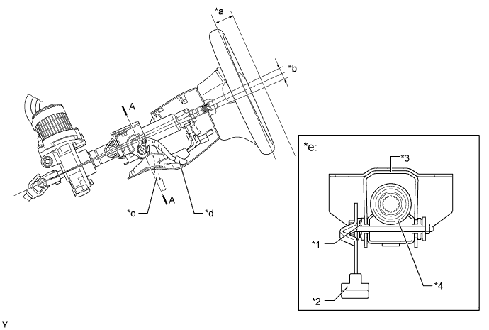
Text in Illustration *1 Tilt and Telescopic Stopper *2 Tilt and telescopic Lever *3 Steering Column Tube Attachment *4 Column Tube *a 40 mm (1.57 in.) *b 30 mm (1.18 in.) *c Unlocked Position *d Locked Position *e A-A Cross Section - -
-
-
Energy Absorbing Mechanism
-
The energy absorbing mechanism mainly consists of a main shaft, column tube and steering intermediate shaft.
-
The steering column assembly is mounted on the instrument panel reinforcement. The steering column assembly and the steering gear assembly are connected with a contractile steering intermediate shaft.
-
When the steering gear moves during a collision (primary collision), the steering intermediate shaft contracts, thus helping reduce the possibility of the steering column and the steering wheel protruding into the cabin.
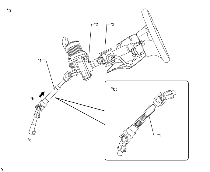
Text in Illustration *1 Steering Intermediate Shaft *2 Steering Column Assembly *3 Breakaway Bracket - - *a Primary Collision *b Contract *c Before Collision *d After Collision -
When a collision impact is transmitted to the steering wheel (secondary collision), the steering wheel and the driver's airbag help absorb the impact. In addition, the main shaft and the column tube contracts. At this time, the friction resistance of the sliding portion absorbs the energy. This sequential energy absorbing mechanism helps absorb the impact of the secondary collision.
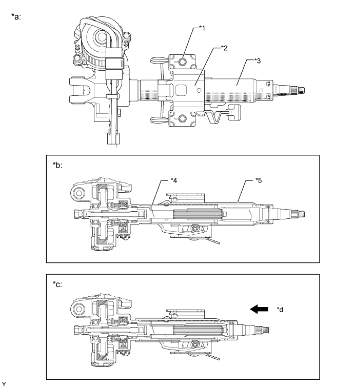
Text in Illustration *1 Capsule (Plastic) *2 Breakaway Bracket *3 Column Tube *4 Inner Tube *5 Outer Tube - - *a Secondary Collision *b Before Collision *c After Collision
(Maximum Contraction)
*d Contract
-
-
Steering Wheel
-
The damper is mounted in the steering wheel through a piece of rubber to make the steering wheel and the damper vibrate at the same time in order to reduce vibrations in the steering, thus improving the riding comfort.
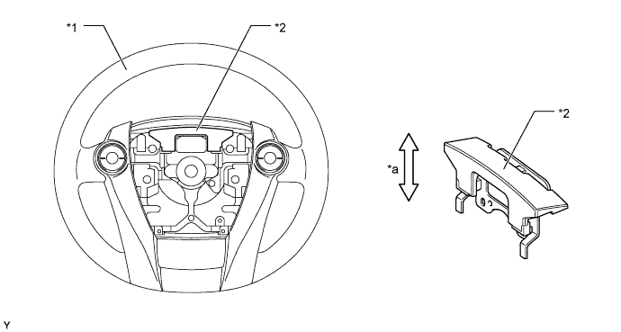
Text in Illustration *1 Steering Wheel *2 Dumper *a Vibration Direction - -
-
-