BRAKE CONTROL SYSTEM DETAILS
-
FUNCTION OF MAIN COMPONENTS
Component Function Brake Booster Pump Assembly
-
Consisting of a pump, pump motor and accumulator, the hydraulic power source portion generates and stores the hydraulic pressure, which the skid control ECU uses for controlling braking.
-
The relief valve is installed in the hydraulic brake booster.
-
The accumulator pressure sensor is installed in the brake actuator.
W/Master Cylinder Brake Booster Assembly Brake Actuator
-
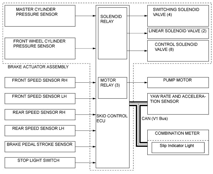
Consists of 4 switching solenoid valves, 2 linear solenoid valves, 8 control solenoid valves.
-
Changes the brake fluid path based on the signals from the skid control ECU during the operations of the ABS with EBD, brake assist, TRC, VSC, hill-start assist control, and VSC+ in order to control the fluid pressure that is applied to the wheel cylinders.
Hydraulic Brake Booster
-
Generates hydraulic pressure in accordance with the amount of effort applied to the brake pedal by the driver.
-
When a malfunction occurs in the brake system, the hydraulic brake booster supplies the fluid pressure (which is generated by the brake pedal effort) directly to the wheel cylinders.
Relief Valve (Built into the skid control ECU)
-
Returns the brake fluid to the reservoir tank to prevent excessive pressure if the pump operates continuously due to a malfunction of the accumulator pressure sensor.
Brake Pedal Stroke Simulator Generates a pedal stroke during braking in accordance with the driver 's pedal effort. Skid Control ECU
-
Monitors the driving conditions of the vehicle in accordance with the signals received from the sensors and through cooperative control with the power management control ECU and EPS ECU calculates the required amount of braking force, and controls the brake actuator.
-
Judges the vehicle driving condition based on signals from each sensor, and controls ABS with EBD, brake assist, TRC, VSC+ and hill-start assist control.
-
Operates the brake booster pump assembly to control accumulator pressure based on accumulator pressure sensor signal.
Brake Fluid Level Warning Switch Detects the low brake fluid level. Brake Pedal Stroke Sensor Directly detects the extent of the brake pedal stroke operated by the driver. Yaw Rate and Acceleration Sensor
-
Detects the vehicle's yaw rate
-
Detects the vehicle's acceleration in the forward, rearward, and lateral.
Steering Angle Sensor Detects the steering direction and angle of the steering wheel. Speed Sensor Detects the wheel speed of each of 4 wheels. Combination Meter ABS Warning Light Lights up to alert the driver when the skid control ECU detects the malfunction in the ABS, EBD, or Brake Assist. Brake Warning Light/Yellow (Minor Malfunction) Lights up to alert the driver when a minor malfunction occurs in the brake system, which does not affect the braking force (such as a malfunction in the regenerative brake). Brake Warning Light/Red (Malfunction)
-
Lights up to alert the driver when the skid control ECU detects the malfunction in the apportioning of the brake.
-
Lights up to inform the driver when the parking brake is on or the brake fluid level is low
Slip Indicator Light
-
Blinks to inform the driver when the ABS, TRC, the VSC or the hill-start assist control is operated.
-
Lights up to alert the driver in the event of malfunction of the TRC or VSC.
Buzzer
-
Emits a warning sound to inform the driver when Hill-start Assist Control operation is started or finished.
-
This buzzer sounds continuously to inform the driver when there is a malfunction in the hydraulic pressure or a failure in the power supply.
Skid Control Buzzer*1, *2 Emits a warning sound to inform the driver during brake control operation (operating dynamic radar cruise control or pre-crash brake). Solenoid Relay (Built into the skid control ECU) Supply or cut off power to solenoid valves in the brake actuator. Pump Motor Relays (Built into the skid control ECU) Normally supplies power to the pump motor using 2 out of 3 relays. Ensures power to the pump motor by using the rest relay if the skid control ECU malfunctions. Power Management Control ECU
-
Actuates the regenerative brake on receiving signal from the skid control ECU.
-
Sends the actual regenerative brake control value to the skid control ECU.
-
Controls the motive force based on an output control request signal received from the skid control ECU while the VSC, TRC or the dynamic radar cruise control system is operating.
Power Steering ECU Operates cooperatively with the skid control ECU to control the steering assist torque.
-
*1: Models with dynamic radar cruise control system
-
*2: Models with pre-crash safety system
-
-
OPERATING CONDITION
-
Hill-start Assist Control
-
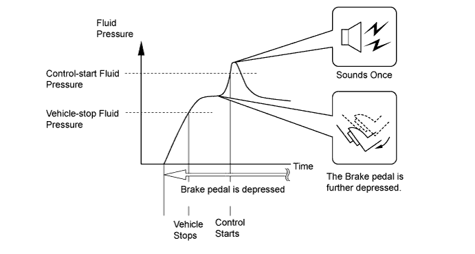
The skid control ECU starts Hill-start Assist Control operation when the operating conditions below are met and the driver further depresses the brake pedal, causing the hydraulic pressure to exceed the control-start hydraulic pressure.
-
When Hill-start Assist Control operation starts, the buzzer in the combination meter will sound once.
Hill-start Assist Control Operation Condition
-
The shift position is in any position other than P.
-
The accelerator pedal is not depressed.
-
The vehicle is at a standstill.
-
The parking brake is not applied
-
-
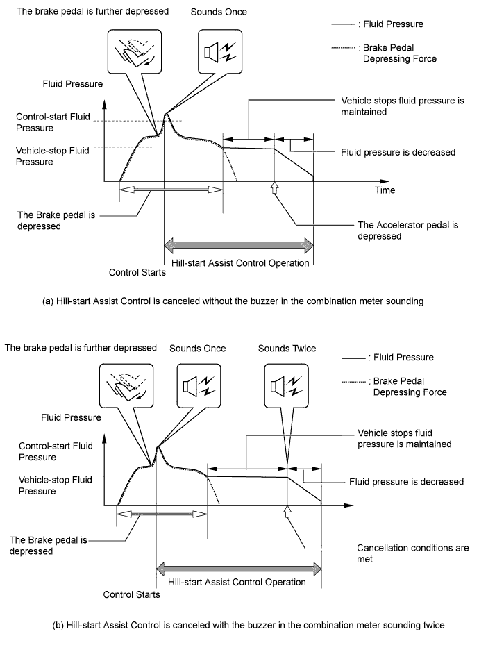
If any one of the below conditions is met during Hill-start Assist Control operation, Hill-start Assist Control will be cancelled causing the slip indicator light to turn off.
-
The buzzer in the combination meter sounds twice if the hill-assist control is cancelled.
Conditions which cause Hill-start Assist Control operation to be canceled (a) Buzzer in combination meter does not sound
-
The driver depresses the accelerator pedal.
(b) Buzzer in combination meter sounds twice
-
The driver changes the shift position to P.
-
The driver depresses the parking brake pedal.
-
The driver depresses the brake pedal.
-
The driver releases the brake pedal for several seconds.
-
The driver keeps the brake pedal depressed continually for 3 minutes.
-
-
-
-
SYSTEM CONTROL
-
Control List
-
The brake control system (ABS with EBD, Brake Assist, TRC and VSC+) has the following controls:
Control Outline Electronically Controlled Brake System Upon receiving signals from the skid control ECU, this system effects hydraulic pressure control at the four wheels. Regenerative Brake Cooperative Control Controls hydraulic braking in order to recover electrical energy by utilizing the regenerative brake of the THS II as much as possible. Anti-lock Brake System (ABS) The ABS helps prevent the wheels from locking when the brakes are applied firmly or when braking on a slippery surface. Electronic Brake Force Distribution (EBD) The EBD control utilizes ABS, realizing proper brake force distribution between the front and rear wheels in accordance with the driving conditions. In addition, during braking while cornering, it also controls the brake forces of the right and left wheels, helping maintain vehicle behavior. Brake Assist The primary purpose of Brake Assist is to provide an auxiliary brake force to assist a driver who cannot generate a large brake force during emergency braking, thus helping draw the vehicle's braking performance. Traction Control (TRC) The TRC helps restrain the slippage of the drive wheels if the driver depresses the accelerator pedal excessively when starting off or accelerating on a slippery surface. VSC+ Vehicle Stability Control (VSC) The VSC helps restrain sideways slippage of the vehicle during a strong front wheel skid or strong rear wheel skid, during cornering. Cooperative Control with EPS Effects cooperative control with the power steering ECU in order to provide steering assist in accordance with the operating conditions of the vehicle. Hill-start Assist Control When starting uphill, this control maintains the brake hydraulic pressure to the four wheels, in order to momentarily prevent the vehicle from descending backward. Brake Control (Operating Dynamic Radar Cruise Control System)*1 When the driving support ECU determines that a large deceleration is required based on the distance to the preceding vehicle and the relative vehicle speed during the dynamic radar cruise control system operation, the skid control ECU operates the brake system according to the signal from the driving support ECU. Brake Control (Operating Pre-crash Safety System)*2 When the driving support ECU determines a high possibility of collision, the skid control ECU activates the pre-crash brake assist or the pre-crash brake according to the signal from the driving support ECU. Motive Force Control during TRC or VSC Operation Transmits a motive force control signal from the skid control ECU to the power management control ECU to limit the motive force while the TRC or VSC is being activated.
-
*1: Models with dynamic radar cruise control system
-
*2: Models with pre-crash safety system
-
-
-
Anti-lock Brake System (ABS)
-
The ABS prevents the wheels from locking during sudden braking or braking on a slippery surface. This provides the proper braking force when the vehicle slips, thus ensuring vehicle stability and excellent braking performance.
Text in Illustration *1 With ABS *2 Without ABS *3 Brake Operation - -
-
-
Electronic Brake Force Distribution (EBD)
-
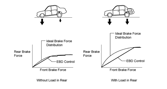
This function controls the brake force that acts on the rear wheels in accordance with the changes in the vehicle conditions such as load factors or deceleration, in order to ensure excellent braking performance.
-
During cornering braking, this function controls the brake force that acts on the left and right wheels in accordance with the vehicle conditions at that time. This ensures vehicle stability and excellent braking performance.

Text in Illustration 
Brake Force 
Control Moment
-
-
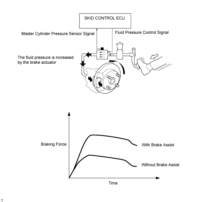
Brake Assist
-
In the brake assist, based on the signals from the master cylinder pressure sensor, the skid control ECU calculates the speed and the amount of the brake pedal application and then determines the intention of the driver to make an emergency braking. If the skid control ECU determines that the driver intends the emergency braking, this function activates the brake actuator to increase the brake fluid pressure, which increases the brake force.
-
-
Traction Control (TRC)
-
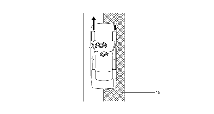
If the driver presses the accelerator pedal aggressively when starting off or accelerating on a slippery surface, the drive wheel could slip due to the excessive amount of torque that is generated. The adjustment of the motive force and the control of the hydraulic brakes of the drive wheels accomplished by THS II allow the TRC function to help minimize the slippage of the drive wheels, and generate the drive force that is appropriate for the road surface conditions.
-
For example, a comparison may be made between two vehicles, one with the TRC function and the other without. If the driver of each vehicle operates the accelerator pedal in a rough manner while driving over a surface with different surface friction characteristics, the drive wheel on the slippery surface could slip as illustrated. As a result, the vehicle could become unstable. However, when the vehicle is equipped with the TRC function, the skid control ECU instantly determines the state of the vehicle and operates the brake actuator in order to apply the brake of the slipping drive wheel. Simultaneously, the skid control ECU effects cooperative control with the power management control ECU, in order to adjust the motive force. Thus, this function can constantly maintain a stable vehicle posture.
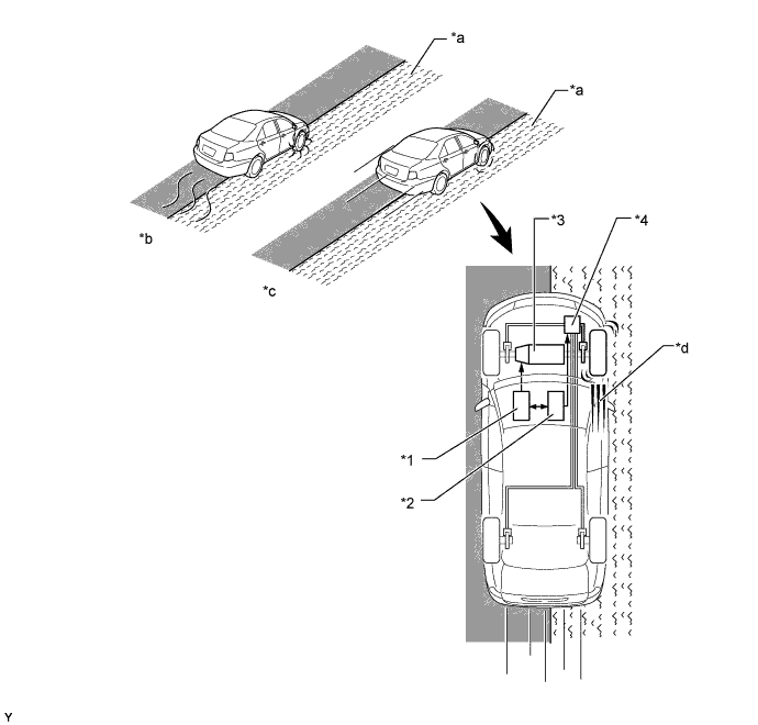
Text in Illustration *1 Power Management Control ECU *2 Skid Control ECU *3
-
Engine and MG2
-
Motive Force Regulation
*4 Brake Actuator *a Slippery Surface *b Without TRC System *c With TRC System *d Brake the slipping drive wheel -
-
-
Vehicle Stability Control (VSC)
-
The followings are two examples that can be considered as circumstances in which the tires exceed their lateral grip limit. The VSC is designed to help control the vehicle behavior by controlling the motive force and the brakes at each wheel when the vehicle is under one of the conditions indicated below.
Text in Illustration *a Front Wheel Skid Tendency *b Rear Wheel Skid Tendency -
To determine the condition of the vehicle, sensors detect the steering angle, vehicle speed, vehicle's yaw rate, and the vehicle's lateral acceleration, which are then calculated by the skid control ECU.
-
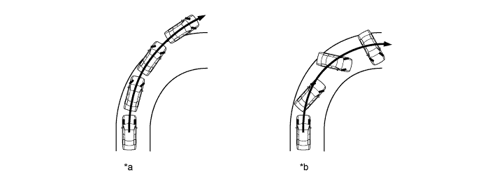
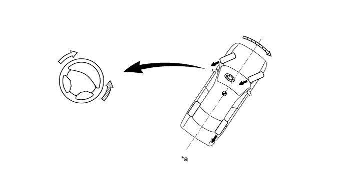
Whether or not the vehicle is in the state of front wheel skid is determined by the difference between the target yaw rate and the vehicle's actual yaw rate. When the vehicle's actual yaw rate is smaller than the yaw rate (a target yaw rate that is determined by the vehicle speed and steering angle) that should be rightfully generated when the driver operates the steering wheel, it means the vehicle is making a turn at a greater angle than the locus of travel. Thus, the skid control ECU determines that there is a large tendency to front wheel skid.

Text in Illustration *a Actual Locus of Travel (Actual Yaw Rate) *b Locus of Travel (Based on the Target Yaw Rate) -
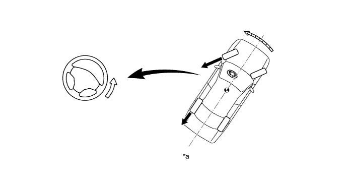
Whether the vehicle is in the state of the rear wheel skid or not is determined by the values of the vehicle's slip angle and the vehicle's slip angular velocity (time-dependent changes in the vehicle's slip angle). When the vehicle's slip angle and the slip angular velocity are large, the skid control ECU determines that the vehicle has a large rear wheel skid tendency.

Text in Illustration *a Direction of Travel of the Vehicle's Center of Gravity *b Slip Angle *c Movement of Vehicle - - -
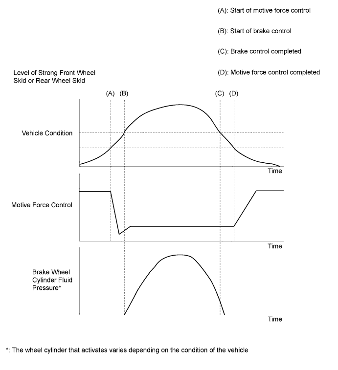
When the skid control ECU determines that the vehicle has a tendency to front wheel skid or rear wheel skid, it decreases the motive force and applies the brake of a front or rear wheel to control the vehicle's yaw moment. The basic operation of the VSC is described below. However, the control method differs depending on the vehicle's characteristics and driving conditions.
-
When the skid control ECU determines that there is a large front wheel skid tendency, it takes countermeasures in accordance with the extent of that tendency. The skid control ECU controls the motive force and applies the brakes of the front wheels and rear wheel of the inner circle of the turn in order to help restrain the front wheel skid tendency.

Text in Illustration *a Making a Right Turn - - Brake Force Control Moment -
When the skid control ECU determines that there is a large rear wheel skid tendency, it takes countermeasures in accordance with the extent of that tendency. It applies the brakes of the front and rear wheels of the outer circle of the turn, and generates an outward moment of inertia in the vehicle, in order to restrain the rear wheel skid tendency. Along with the reduction in the vehicle speed caused by the braking force, excellent vehicle stability is ensured.

Text in Illustration *a Making a Right Turn - - Brake Force Control Moment
-
-
Hill-start Assist Control
-
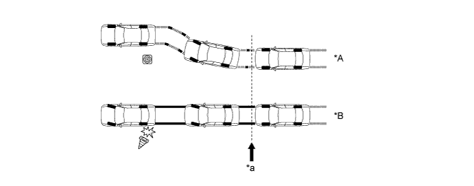
When the vehicle starts off on a steep or slippery hill, the vehicle could descend backward while the driver switches from the brake pedal to the accelerator pedal, thus making it difficult for the vehicle to start off. To prevent this from occurring, the hill-start assist control temporarily (approximately 2 seconds at the maximum) applies the brakes to all the wheels in order to prevent the vehicle from descending backward.
-
Without the hill-start assist control, the driver must quickly and precisely switch from the brake pedal to the accelerator pedal. With the hill-start assist control, however, the driver can start off easily and operate the pedal in a relaxed manner because the hill-start assist control prevents the vehicle from descending backward.
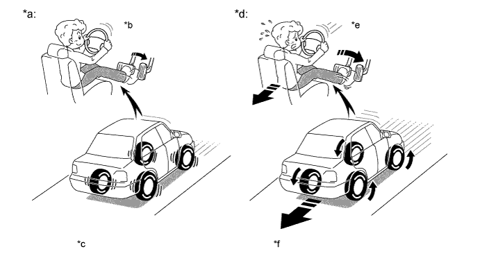
Text in Illustration *a With Hill-start Assist Control *b Easy Control *c Prevent the vehicle from descending backward *d Without Hill-start Assist Control *e Difficult Control *f Increase the backward speed of the vehicle
-
-
Outline of Brake Control (Operating Dynamic Radar Cruise Control System)
-
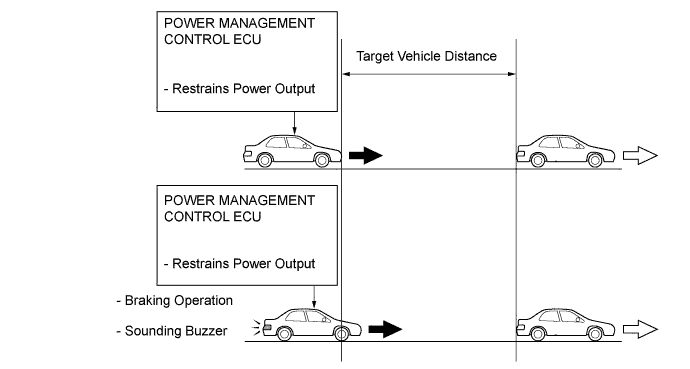
If the distance from the vehicle ahead decreases during a dynamic radar cruise control system operation, it might not be possible for the vehicle to attain a sufficient amount of deceleration by restraining the engine and motor output controlled by the power management control ECU. In this instance, even if the driver is not depressing the brake pedal, the skid control ECU activates the brake actuator and starts braking, in order to attain the target deceleration rate that is constantly calculated and requested by the driving support ECU. As a result, the stop lights illuminate.
-
At the end of braking, the skid control ECU gradually decreases the braking force and ends it in order to decelerate smoothly.
-
If further deceleration is required, the system sounds a skid control buzzer to alert the driver to apply the brakes.
-
-
Outline of Brake Control (Operating Pre-crash Safety System)
-
If the driving support ECU determines that the possibility of a collision is high, the ECU sends the pre-crash brake assist request signal to the skid control ECU. Upon receiving the signal, the skid control ECU switches the brake assist to standby mode. When the driver depresses the brake pedal, the skid control ECU operates the brake assist based on the master cylinder pressure sensor.
-
If the driving support ECU determines an unavoidable collision, the ECU sends the pre-crash brake request signal to the skid control ECU. The skid control ECU then activates the brake actuator as a pre-crash brake control and decelerates the vehicle. Thus, the system helps to lessen impact in collision.
-
If the skid control ECU determines that the pedal depression force and braking force are both small when the brake assist is activated, the skid control ECU immediately activates the pre-crash brake control to ensure the braking force.
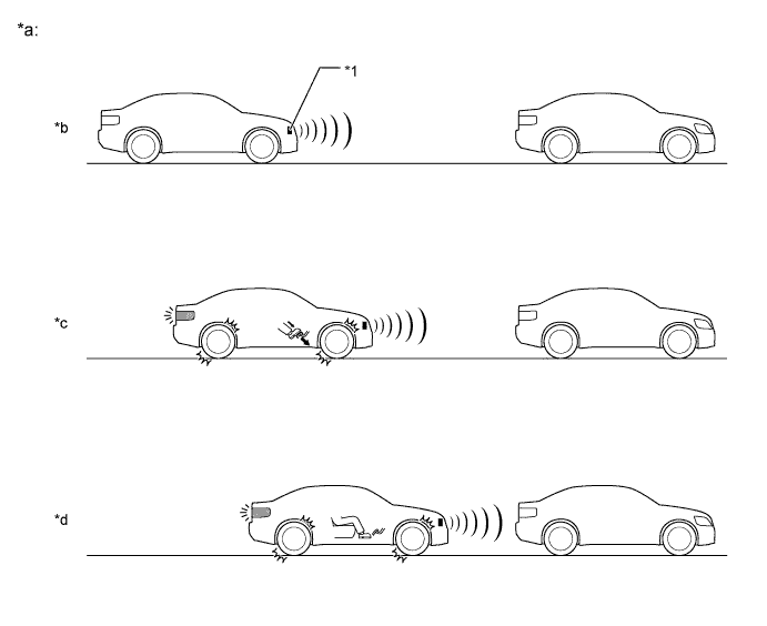
Text in Illustration *1 Millimeter Wave Radar Sensor - - *a Brake Operation *b Brake Assist Standby Mode *c Brake Assist Operation *d Brake Operation
(Models with Pre-crash Brake)
-
-
Motive Force Control during TRC or VSC Operation
-
During the TRC or VSC operation, the skid control ECU outputs the motive force control signal to the power management control ECU. Upon receiving this signal, the power management control ECU inhibits the motive force.
-
-
Cooperative Control with EPS
-
If the driver suddenly applies the brakes on a road surface with a considerable difference in friction coefficient between the right and left wheels, the difference in the brake force between the right and left wheels will cause the vehicle posture to become unstable and create a yaw moment. In this state, the skid control ECU controls the ABS and VSC to stabilize the vehicle posture. At the same time, it effects cooperative control with the EPS to provide steering torque assist, which facilitates the driver's steering maneuvers to stabilize the vehicle posture.
Text in Illustration *a Slippery Surface - - Brake Force 
Assisting Direction 
Yaw Moment During Brake Controlling - - -
If the driver suddenly starts off or accelerates on a road surface with a considerable difference in friction coefficient between the right and left wheels, the slippage of a drive wheel will cause the vehicle posture to become unstable and negatively affect its acceleration performance. In this state, the skid control ECU causes the TRC to control the hydraulic brake of the slipping drive wheel, and requests the power management control ECU to effect motive force control. At the same time, it effects cooperative control with the EPS to provide steering torque assist, which facilitates the driver's steering maneuvers to stabilize the vehicle posture.
Text in Illustration *a Slippery Surface - - Drive Force Assisting Direction Yaw Moment During Accelerating - - -
When the skid control ECU determines a front wheel skid tendency, it controls the VSC to dampen the front wheel skid. At the same time, it effects the cooperative control with the EPS to provide steering torque assist, which controls the driver's steering maneuvers to stabilize the vehicle posture. Steering torque assists are provided to inform the driver of the front wheel skid, and to prevent the driver's excessive turning of the steering wheel. In the assist for preventing excessive turning, it increases the resistance to counter the driver's steering effort, if the driver turns the steering wheel excessively.
Text in Illustration *a Front Wheel Skid Tendency - - Brake Force Assisting Direction for Information of Front Wheel Skid Assisting Direction for Preventing Excessive Turning Control Moment -
When the skid control ECU determines a rear wheel skid tendency, it controls the VSC to dampen the rear wheel skid. At the same time, it effects the cooperative control with the EPS to provide steering torque assist, which facilitates the driver's steering maneuvers in the direction to correct the rear wheel skid.
Text in Illustration *a Rear Wheel Skid Tendency - - Brake Force Assisting Direction Control Moment - -
-
-
-
CONSTRUCTION
-
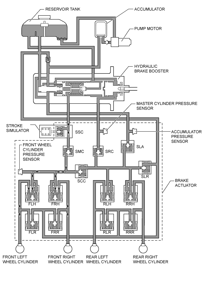
Brake Actuator
-
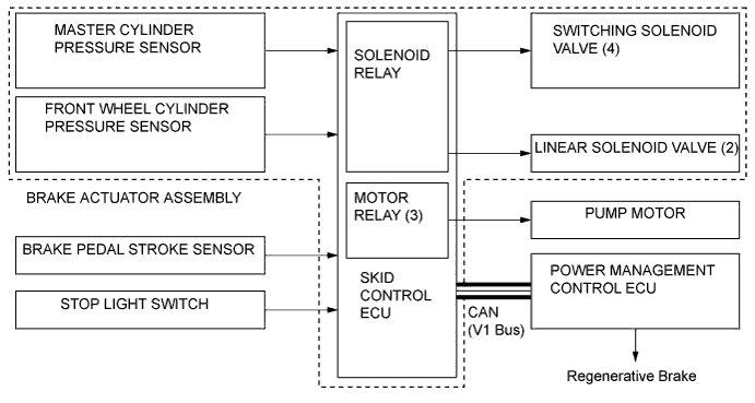
The brake actuator consists of the actuator portion and skid control ECU.
-
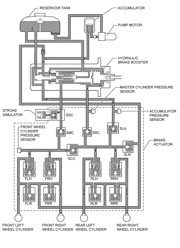
The brake actuator regulates the hydraulic brake pressure to each wheel cylinder.
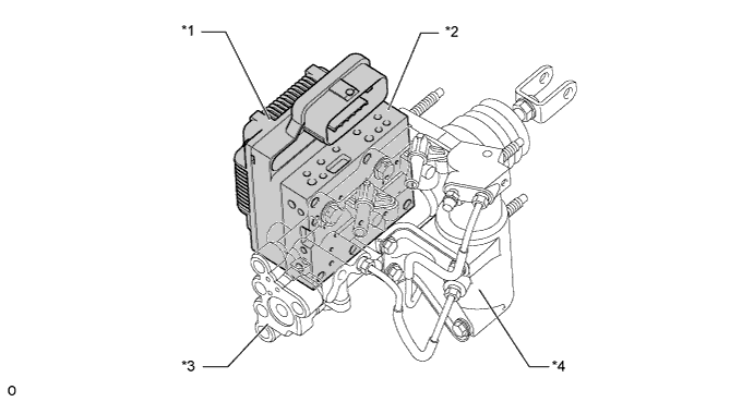
Text in Illustration *1 Skid Control ECU *2 Actuator Portion *3 Hydraulic Brake Booster *4 Stroke Simulator 
Brake Actuator - - -
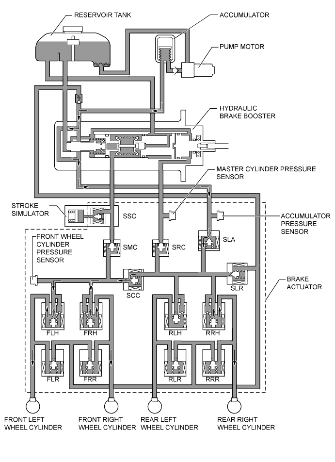
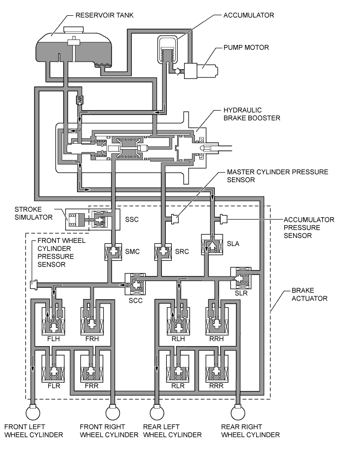
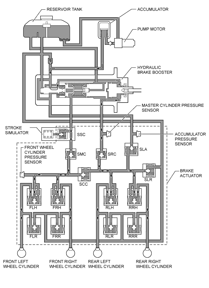
The construction of the brake actuator, and the role of each part, is as follows.
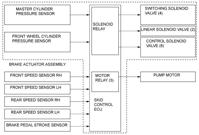
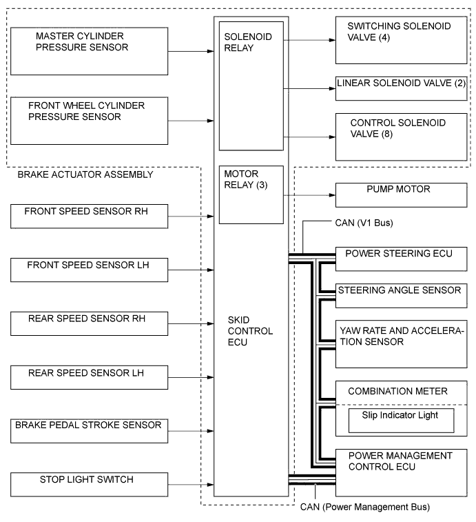
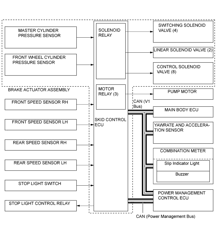
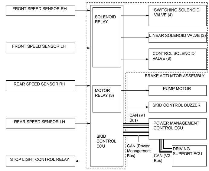
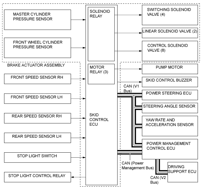
Component Function Linear Solenoid Valve Controls the wheel cylinder pressure to generate a braking force responsive to the braking force requirement when the brake pedal is depressed normally. Switching Solenoid Valve Switches the brake hydraulic path when the brake control system is activated. Control Solenoid Valve Controls the wheel cylinder pressure when the ABS with EBD, brake assist, TRC, hill-start assist control and VSC+ are activated. Master Cylinder Pressure Sensor The master cylinder pressure sensor converts the fluid pressure generated by the hydraulic brake booster into electrical signals and transmits them to the skid control ECU. Accordingly, the skid control ECU determines the braking force required by the driver. Front Wheel Cylinder Pressure Sensor This sensor detects the fluid pressure that acts on the respective wheel cylinders and transmits them to the skid control ECU in the form of feedback. Accordingly, the skid control ECU monitors the fluid pressure of the wheel cylinders and controls the control solenoid valve, in order to achieve the optimal wheel cylinder pressures. Accumulator Pressure Sensor The accumulator pressure sensor constantly detects the brake fluid pressure in the accumulator and transmits the signals to the skid control ECU. Accordingly, the skid control ECU controls the pump motor. 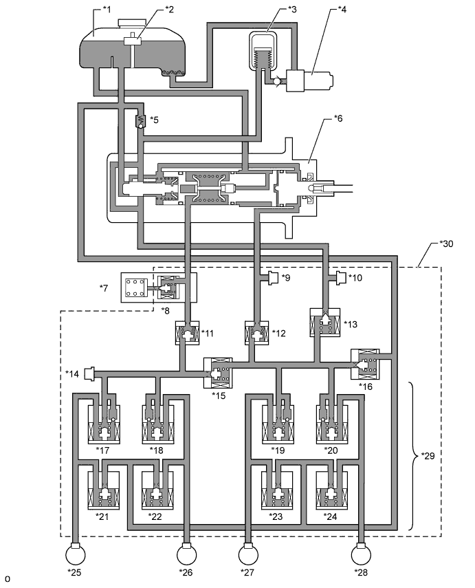
Text in Illustration *1 Reservoir Tank *2 Brake Fluid Level Warning Switch *3 Accumulator *4 Pump Motor *5 Pressure Relief Valve *6 Hydraulic Brake Booster *7 Stroke Simulator *8 Switching Solenoid Valve SSC *9 Master Cylinder Pressure Sensor *10 Accumulator Pressure Sensor *11 Switching Solenoid Valve SMC *12 Switching Solenoid Valve SRC *13 Linear Solenoid Valve SLA *14 Front Wheel Cylinder Pressure Sensor *15 Switching Solenoid Valve SCC *16 Linear Solenoid Valve SLR *17 Pressure Holding Solenoid Valve FLH *18 Pressure Holding Solenoid Valve FRH *19 Pressure Holding Solenoid Valve RLH *20 Pressure Holding Solenoid Valve RRH *21 Pressure Reduction Solenoid Valve FLR *22 Pressure Reduction Solenoid Valve FRR *23 Pressure Reduction Solenoid Valve RLR *24 Pressure Reduction Solenoid Valve RRR *25 Front Left Wheel Cylinder *26 Front Right Wheel Cylinder *27 Rear Left Wheel Cylinder *28 Rear Right Wheel Cylinder *29 Control Solenoid Valve *30 Brake Actuator
-
-
Hydraulic Brake Booster
-
The hydraulic brake booster consists of the operating rod which is directly connected to the brake pedal, power piston, master cylinder piston, regulator piston and the spool valve to switch the brake fluid passage.
-
The operating rod is directly connected to the power piston, by which the operating force of the brake pedal is transmitted.
-
The regulator piston is directly connected to the spool valve, and through which the master cylinder pressure is applied to the regulator piston in the advance direction (left direction in the illustration) and the pressure boosted by the brake booster is applied to the piston in the retard direction (right direction in the illustration), thus balancing the pressures in both directions. In addition, a return spring is placed in the regulator piston to ensure the return force of the spool valve when no pressure is applied.
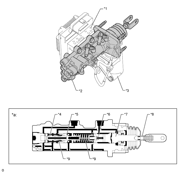
Text in Illustration *1 Brake Actuator *2 Hydraulic Brake Booster *3 Stroke Simulator *4 Spool Valve *5 Regulator Piston *6 Master Cylinder Piston *7 Power Piston *8 Operating Rod *9 Return Spring - - *a Hydraulic Brake Booster Cross Section - - 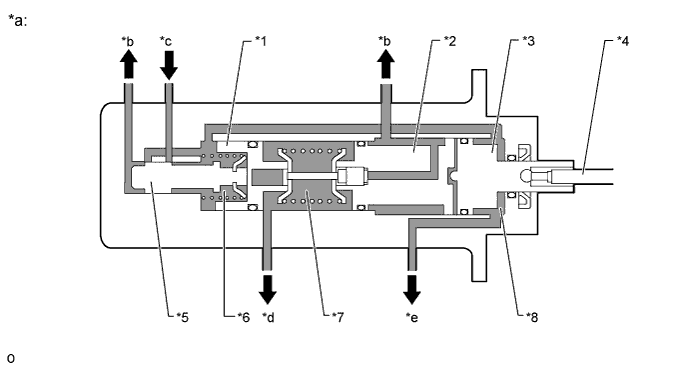
Text in Illustration *1 Regulator Piston *2 Master Cylinder Piston *3 Power Piston *4 Operating Rod *5 Spool Valve *6 Regulator Chamber *7 Master Cylinder Chamber *8 Booster Chamber *a Simplified Diagram *b To Reservoir Tank *c From Accumulator *d To Front Brake *e To Rear Brake - -
-
-
Stroke Simulator
-
The stroke simulator is positioned beside the hydraulic brake booster. It generates a pedal stroke in accordance with the driver's pedal effort during braking. Containing 2 types of coil springs with different spring constants, the stroke simulator provides pedal stroke characteristics in relation to the master cylinder pressure.
-
To shut off the flow of fluid from the master cylinder when the system is failed, a two-position solenoid valve has been provided.
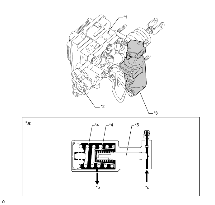
Text in Illustration *1 Brake Actuator *2 Hydraulic Brake Booster *3 Stroke Simulator *4 Coil Spring *5 Piston - - *a Stroke Simulator Cross Section *b To Reservoir Tank *c From Hydraulic Brake Booster - -
-
-
Brake Booster Pump Assembly
-
Brake booster pump assembly consists of pump, pump motor and accumulator.
-
A plunger type pump is used. This pump is operated by rotation of the camshaft driven by the motor, and then supplies high-pressurized fluid to the accumulator.
-
The high-pressurized nitrogen gas is charged and sealed in the accumulator. The accumulator has been made more compact by using a metallic bellow-formed tube.
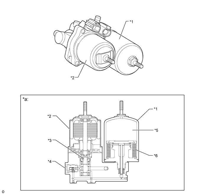
Text in Illustration *1 Accumulator *2 Pump Motor *3 Camshaft *4 Pump *5 Nitrogen Gas *6 Bellows-formed *a Cross Section - -
-
-
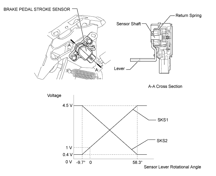
Brake Pedal Stroke Sensor
-
This sensor, which contains a contact type variable resistor, detects the extent of the brake pedal stroke and transmits it to the skid control ECU.
Tech Tips
-
To install a brake pedal stroke sensor, which is available as a service part, perform as follows:
-
The sensor lever is secured with a pin to "0" stroke. (Do not detach the pin until the installation has been completed.)
-
In this state, install the sensor on the brake pedal (in the OFF state) on the vehicle.
-
After completing the installation, firmly press the brake pedal once to break off the pin that is securing the sensor in place.
-
Make sure the broken pin does not remain in the sensor lever.
-
After replacing the brake pedal stroke sensor, initialization of brake pedal stroke sensor must be required on the skid control ECU side. For Details, refer to the Repair Manual.
-
-
-
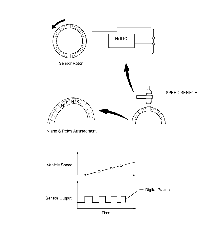
Speed Sensor
-
An active type speed sensor is used. This sensor contains a Hall IC.
-
The sensor rotor, which consists of N and S poles that are arranged in a circle, is integrated with the hub bearing inner race.
-
An active type speed sensor uses a Hall IC to detect magnetic field changes caused when the sensor rotor rotates, and the sensor outputs the detected information to the skid control ECU as digital pulses.
-
To detect the vehicle speed, the frequency of the output pulses is used. Because the active type sensor outputs digital pulses, it can detect vehicle speeds even when the vehicle is nearly stationary.
-
-
Yaw Rate and Acceleration Sensor
-
The yaw rate sensor is built into the acceleration sensor.
-
The yaw rate sensor detects acceleration in the horizontal forward-backward and left-right directions using the signals from two acceleration sensors, which are fitted at an angle of 45° to the front and back directions of the vehicle body, and transmits signals to the skid control ECU.
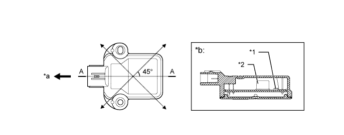
Text in Illustration *1 Acceleration Sensor *2 Yaw Rate Sensor *a Front *b A-A Cross Section Tech Tips
After replacing the yaw rate sensor, or the skid control ECU, initialization of the yaw rate sensor is required. For the actual procedure, refer to the Repair Manual.
-
-
Steering Angle Sensor
-
The steering angle sensor detects the steering direction and angle, and sends this signal to the skid control ECU.
-
The steering angle sensor contains two sets of magnetic reluctance elements that detect the rotational movement of a magnet that is built into the detection gear. Thus, the sensor detects the changes that occur in the magnetic reluctance elements along with the rotational movement of the detection gear, in order to detect the rotational movement of the steering wheel.
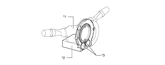
Text in Illustration *1 Combination Switch Assembly *2 Steering Angle Sensor *3 Detection Gear - - Note
Do not remove the steering angle sensor from the spiral cable. If there is a malfunction in the steering angle sensor, replace the spiral cable with steering angle sensor.
-
-
-
OPERATION
-
Hydraulic Brake Booster
-
When the brake pedal is depressed by the driver, the operating force of the brake pedal is transmitted from the operating rod via the power piston to the master cylinder piston. The return spring of the master cylinder chamber has a higher setting load than that of the regulator piston, thus allowing the regulator piston to move forward before the master cylinder chamber is compressed.
-
The spool valve closes the oil passage to the reservoir tank and the booster chamber and opens the one from the accumulator and the booster chamber, and this allows the fluid pressure to be applied to the booster chamber, generating a boosted force and further boosting the brake pedal force. When the fluid pressure is applied to the booster chamber, the boosted force overcomes the return spring force, compressing the master cylinder and increasing the fluid pressure. In addition, the fluid pressure in the booster chamber increases the fluid pressure in the rear brake oil passage.
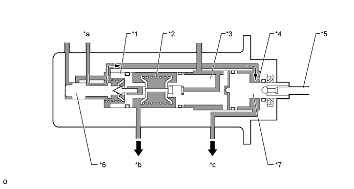
Text in Illustration *1 Regulator Piston *2 Return Spring *3 Master Cylinder Piston *4 Booster Chamber *5 Operating Rod *6 Spool Valve *7 Power Piston - - *a From Accumulator *b To Front Brake *c To Rear Brake - - -
When the driver's pedal operation is stopped and the pedal operating force and the master cylinder pressure are balanced, the forces are respectively applied to the front and rear of the regulator piston, in other words, the forces respectively generated by the master cylinder pressure and the regulator pressure are balanced, therefore, the spool valve closes the passage between the booster chamber and the accumulator, and also to the reservoir tank.
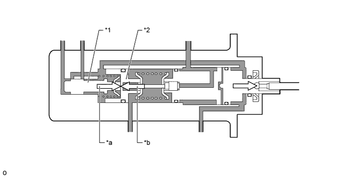
Text in Illustration *1 Spool Valve *2 Regulator Piston *a Regulator Pressure *b Master Cylinder Pressure -
When the driver's pedal operating force lowers, the master cylinder pressure drops, therefore, the force applied to the regulator piston return side becomes larger relatively and the regulator piston and the spool valve move further rearward, and this opens the fluid passage between the reservoir tank and the booster chamber.
-
As a result, the brake fluid in the hydraulic brake booster is returned to the reservoir tank, decreasing the booster chamber pressure and balancing the booster chamber pressure against the reduced master cylinder pressure. This repetitive operation decreases the booster chamber pressure and the master cylinder pressure in accordance with the pedal operating force.
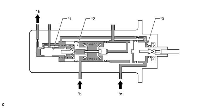
Text in Illustration *1 Spool Valve *2 Regulator Piston *3 Booster Chamber - - *a To Reservoir Tank *b From Front Brake *c From Rear Brake - -
-
-
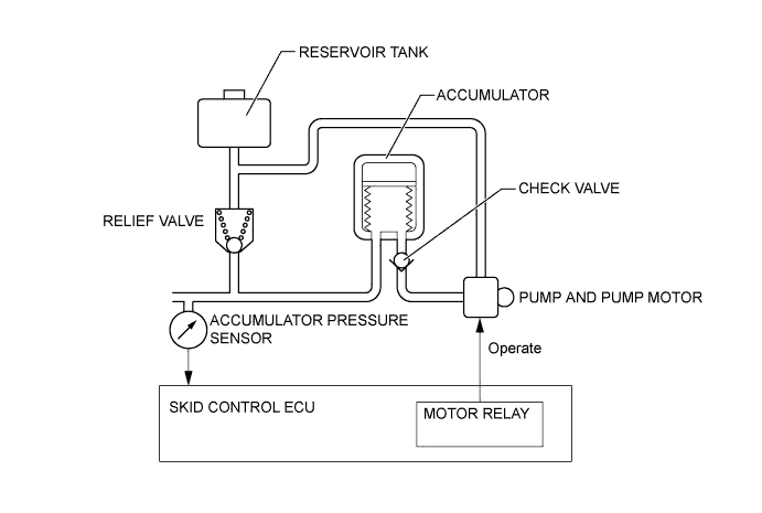
Brake Booster Pump Assembly
-
The brake fluid that is discharged by the pump passes through the check valve and is stored in the accumulator. The hydraulic pressure that is stored in the accumulator is used for providing the hydraulic pressure that is needed for normal braking and for operating the brake control.
-
The pump motor is activated upon receipt of signals from the skid control ECU to turn on the motor relays built into the skid control ECU.
-
The accumulator pressure sensor constantly monitors the pressure in the accumulator and transmits it to the skid control ECU. If the accumulator pressure drops below the set pressure, the skid control ECU sends an activation signal to the motor relay in order to actuate the pump motor until the pressure in the accumulator reaches the set pressure.
-
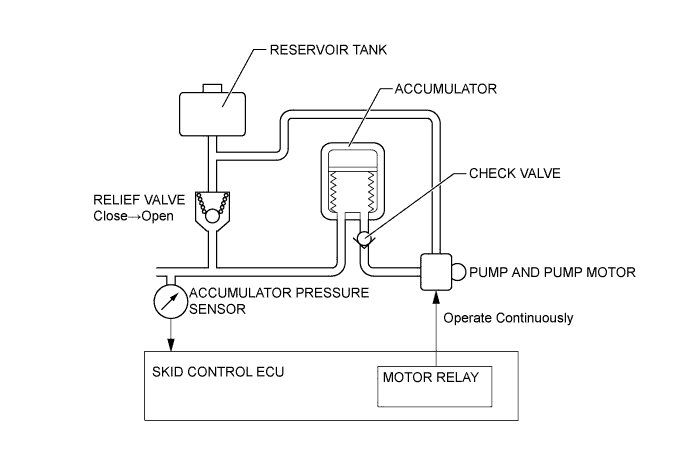
If the pump and the pump motor continue to operate unintentionally, and the accumulator pressure sensor fails, a high pressure would be created in the accumulator. At this time, the relief valve will open and return the brake fluid to the reservoir tank, to reduce the accumulator pressure.
-
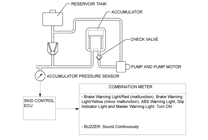
If the accumulator pressure drops abnormally to a level below the pressure set at the ECU, the skid control ECU illuminates the brake warning light / red (malfunction), the brake warning light / yellow (minor malfunction), ABS warning light and the master warning light. Then, the skid control buzzer sounds to alert the driver of the abnormal hydraulic pressure.
-
-
Normal Brake Operation (with Regenerative Brake Cooperative Control)
-
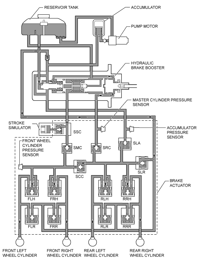
During normal braking, the switching solenoid valves SSC and SCC open and the switching solenoid valves SMC and SRC close, and thus the fluid pressure circuit from the hydraulic brake booster to each wheel cylinder is individually separated. Each of the wheel cylinder pressures can be increased, retained and decreased by controlling the linear solenoid valves SLA and SLR under the condition.
-
The skid control ECU calculates the braking force required by the driver in accordance with the signals received from the master cylinder pressure sensor and the brake pedal stroke sensor. Then, the skid control ECU calculates the regenerative brake force value out of the required brake force and transmits the calculated value to the power management control ECU. Upon receiving the value, the power management control ECU generates a regenerative brake force. At the same time, the power management control ECU transmits the actual regenerative brake force value to the skid control ECU. The skid control ECU controls the solenoid valves in order to cause the hydraulic brake system to generate a brake force value (which is obtained by subtracting the regenerative brake force from the brake force value required by the driver).
-
The skid control ECU calculates the target wheel cylinder pressure (equivalent to the brake force required by the driver) in accordance with the signals received from the master cylinder pressure sensor and the brake pedal stroke sensor. The skid control ECU compares the wheel cylinder pressure with the target wheel cylinder pressure. If the wheel cylinder pressure is lower than the target wheel cylinder pressure, the skid control ECU boosts the pressure in the brake actuator. Accordingly, the fluid pressure in the accumulator is fed into the wheel cylinder. Moreover, this operation is the same when the hydraulic brake force must be increased in order to effect cooperative control in accordance with the changes in the regenerative brake force.
Item Normal Braking Increase Mode Linear Solenoid Valve SLA On (Half-open*) SLR Off (Close) Switching Solenoid Valve SSC On (Open) SCC ↑ SMC On (Close) SRC ↑ Control Solenoid Valve FLH Off (Open) FRH ↑ RLH ↑ RRH ↑ FLR Off (Close) FRR ↑ RLR ↑ RRR ↑ Tech Tips
*: The solenoid valve constantly regulates the amount of opening of the valve in accordance with the use conditions in order to control the fluid pressure.
-
The skid control ECU calculates the target wheel cylinder pressure (equivalent to the brake force required by the driver) in accordance with the signals received from the master cylinder pressure sensor and the brake pedal stroke sensor. The skid control ECU compares the wheel cylinder pressure with the target wheel cylinder pressure. If they are equal, the skid control ECU controls the brake actuator in the hold state. Accordingly, the wheel cylinder will be held at a constant pressure.

Item Normal Braking Holding Mode Linear Solenoid Valve SLA Off (Close) SLR ↑ Switching Solenoid Valve SSC On (Open) SCC ↑ SMC On (Close) SRC ↑ Control Solenoid Valve FLH Off (Open) FRH ↑ RLH ↑ RRH ↑ FLR Off (Close) FRR ↑ RLR ↑ RRR ↑ -
The skid control ECU calculates the target wheel cylinder pressure (equivalent to the brake force required by the driver) in accordance with the signals received from the master cylinder pressure sensor and the brake pedal stroke sensor. The skid control ECU compares the wheel cylinder pressure with the target wheel cylinder pressure. If the wheel cylinder pressure is higher than the target wheel cylinder pressure, the skid control ECU reduces the pressure in the brake actuator. Accordingly, the pressure in the wheel cylinder decreases. Moreover, this operation is the same when the hydraulic brake force must be decreased in order to effect cooperative control in accordance with the changes in the regenerative brake force.
Item Normal Braking Reduction Mode Linear Solenoid Valve SLA Off (Close) SLR On (Half - Open*) Switching Solenoid Valve SSC On (Open) SCC ↑ SMC On (Close) SRC ↑ Control Solenoid Valve FLH Off (Open) FRH ↑ RLH ↑ RRH ↑ FLR Off (Close) FRR ↑ RLR ↑ RRR ↑ Tech Tips
*: The solenoid valve constantly regulates the amount of opening of the valve in accordance with the use conditions in order to control the fluid pressure.
-
-
ABS with EBD
-
Based on the signals received from the 4 speed sensors, the skid control ECU calculates each wheel speed and deceleration, and checks wheel slipping conditions. According to the slipping condition, the skid control ECU controls the pressure holding valve and pressure reduction valve in order to adjust the fluid pressure of the each wheel cylinder in the following 3 modes: pressure reduction, pressure holding, and pressure increase modes.
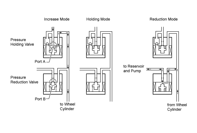
Not Activated Normal Braking - - Activated Increase Mode Holding Mode Reduction Mode Pressure Holding Solenoid Valve OFF (Open) ON (Close) ← Pressure Reduction Solenoid Valve OFF (Close) ← ON (Open) Wheel Cylinder Pressure Increase Hold Reduce
-
-
Brake Assist
-
In the event of emergency braking, the skid control ECU detects the driver's intention based on the speed of the pressure increase in the master cylinder determined by the master cylinder pressure sensor signal. If the skid control ECU judges the need for additional brake assist, the fluid pressure from the accumulator is directed to the wheel cylinder to apply a greater fluid pressure than the regulator.
Item Normal Braking Increase Mode Brake Assist Activated Linear Solenoid Valve SLA On (Half - Open*) On (Half - Open*) SLR Off (Close) Off (Close) Switching Solenoid Valve SSC On (Open) On (Open) SCC ↑ ↑ SMC On (Close) On (Close) SRC ↑ ↑ Control Solenoid Valve FLH Off (Open) Off (Open) FRH ↑ ↑ RLH ↑ ↑ RRH ↑ ↑ FLR Off (Close) Off (Close) FRR ↑ ↑ RLR ↑ ↑ RRR ↑ ↑ Tech Tips
*: The solenoid valve constantly regulates the amount of opening of the valve in accordance with the use conditions in order to control the fluid pressure.
-
-
TRC
-
The fluid pressure stored in the accumulator is regulated by the switching solenoid valves and control solenoid valves to the required pressure. Thus, the wheel cylinders of the drive wheels are controlled in the following 3 modes: pressure reduction, pressure holding, and pressure increase modes to control the slippage of the drive wheels. The diagram below shows the hydraulic circuit in the pressure increase mode when the TRC is activated. The pressure holding solenoid valve and the pressure reduction solenoid valve are turned on/off according to the ABS with EBD operation pattern.

Item TRC not Activated TRC Activated Increase Mode Holding Mode Reduction Mode Linear Solenoid Valve SLA Off (Close) On (Open) On (Open) On (Open) SLR ↑ Off (Close) Off (Close) Off (Close) Switching Solenoid Valve SSC On (Open) On (Open) On (Open) On (Open) SCC ↑ ↑ ↑ ↑ SMC Off (Open) On (Close) On (Close) On (Close) SRC ↑ ↑ ↑ ↑ Control Solenoid Valve FLH Off (Open) Off (Open) On (Close) On (Close) FRH ↑ ↑ ↑ ↑ RLH ↑ On (Close) ↑ ↑ RRH ↑ ↑ ↑ ↑ FLR Off (Close) Off (Close) Off (Close) On (Open) FRR ↑ ↑ ↑ ↑ RLR ↑ ↑ ↑ Off (Close) RRR ↑ ↑ ↑ ↑
-
-
VSC
-
The VSC, by way of solenoid valves, controls the fluid pressure that is stored in the accumulator and applies it to the brake wheel cylinder of each wheel in the following 3 modes: pressure reduction, pressure holding, and pressure increase modes. As a result, the tendency to front wheel skid or rear wheel skid is controlled.
-
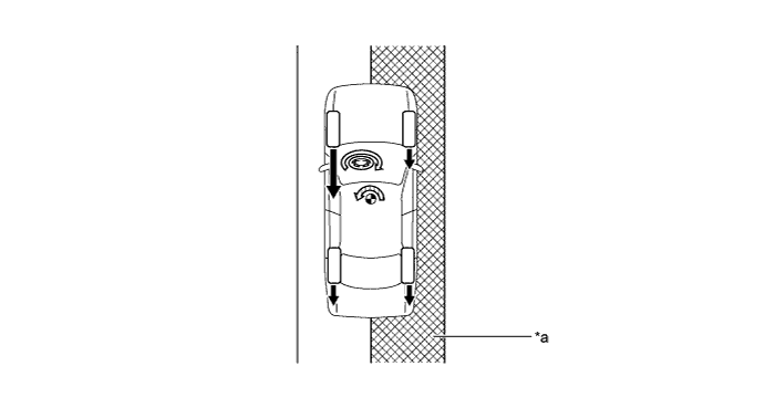
In the front wheel skid restraining control, the brakes of the front wheels and rear wheel of the inner circle of the turn is applied. Also, depending on whether the brake is on or off and the condition of the vehicle, there are circumstances in which the brake might not be applied to the wheels even if the wheel is targeted for braking. The diagram below shows the hydraulic circuit in the pressure increase mode, as it controls the front wheel skid condition while the vehicle makes a right turn. In other operating modes, the pressure holding valve and the pressure reduction valve are turned on/off according to the ABS with EBD operation pattern.
Item VSC not Activated VSC Activated Increase Mode Holding Mode Reduction Mode Linear Solenoid Valve SLA Off (Close) On (Open) On (Open) On (Open) SLR ↑ Off (Close) Off (Close) Off (Close) Switching Solenoid Valve SSC On (Open) On (Open) On (Open) On (Open) SCC ↑ ↑ ↑ ↑ SMC Off (Open) On (Close) On (Close) On (Close) SRC ↑ ↑ ↑ ↑ Control Solenoid Valve FLH Off (Open) Off (Open) On (Close) On (Close) FRH ↑ ↑ ↑ ↑ RLH ↑ On (Close) ↑ ↑ RRH ↑ Off (Open) ↑ ↑ FLR Off (Close) Off (Close) Off (Close) On (Open) FRR ↑ ↑ ↑ ↑ RLR ↑ ↑ ↑ Off (Close) RRR ↑ ↑ ↑ On (Open) -
In the rear wheel skid restraining control, the brakes of the front and rear wheels on the outer circle of the turn are applied. Also, depending on whether the brake is on or off and the condition of the vehicle, there are circumstances in which the brake might not be applied to the wheels even if the wheel is targeted for braking. The diagram below shows the hydraulic circuit in the pressure increase mode, as it controls the rear wheel skid condition while the vehicle makes a right turn. In other operating modes, the pressure holding valve and the pressure reduction valve are turned on/off according to the ABS with EBD operation patterns.
Item VSC not Activated VSC Activated Increase Mode Holding Mode Reduction Mode Linear Solenoid Valve SLA Off (Close) On (Open) On (Open) On (Open) SLR ↑ Off (Close) Off (Close) Off (Close) Switching Solenoid Valve SSC On (Open) On (Open) On (Open) On (Open) SCC ↑ ↑ ↑ ↑ SMC Off (Open) On (Close) On (Close) On (Close) SRC ↑ ↑ ↑ ↑ Control Solenoid Valve FLH Off (Open) Off (Open) On (Close) On (Close) FRH ↑ On (Close) ↑ ↑ RLH ↑ Off (Open) ↑ ↑ RRH ↑ On (Close) ↑ ↑ FLR Off (Close) Off (Close) Off (Close) On (Open) FRR ↑ ↑ ↑ Off (Close) RLR ↑ ↑ ↑ On (Open) RRR ↑ ↑ ↑ Off (Close)
-
-
Hill-start Assist Control
-
Hill-start assist control helps maintain 4-wheel hydraulic pressure by operating the linear solenoid valve when the driver releases the brake pedal until depressing the accelerator pedal.
-
Based on the information provided by various sensors, switches, and power management control ECU, the skid control ECU determines whether to activate hill-start assist control.
-
During hill-start assist control, the slip indicator light blinks and the stop light are illuminated.

Item Hill-start Assist Control not Activated Hill-start Assist Control Activated Holding Mode Reduction Mode Linear Solenoid Valve SLA Off (Close) Off (Close) Off (Close) SLR ↑ ↑ On (Open) Switching Solenoid Valve SSC On (Open) On (Open) On (Open) SCC ↑ ↑ ↑ SMC Off (Open) On (Close) On (Close) SRC ↑ ↑ ↑ Control Solenoid Valve FLH Off (Open) Off (Open) Off (Open) FRH ↑ ↑ ↑ RLH ↑ ↑ ↑ RRH ↑ ↑ ↑ FLR Off (Close) Off (Close) Off (Close) FRR ↑ ↑ ↑ RLR ↑ ↑ ↑ RRR ↑ ↑ ↑
-
-
Brake Control Operation (Operating Dynamic Radar Cruise Control)
-
The skid control ECU operates the brakes by receiving a motive force request signal from the driving support ECU while the dynamic radar cruise control system is being activated. This brake control operates in the same way as the normal brake operation.
-
-
Brake Control Operation (Operating Pre-crash Safety System)
-
When the driver presses the brake pedal while the skid control ECU is switched to the brake assist standby mode, the brake assist control will operate even if the application of the brakes is not considered emergency braking. At this time, the brake control is performed in the same way as the normal brake assist operation.
-
If a collision is unavoidable, the skid control ECU actuates the motor in the power supply portion to apply direct pressure to the wheel cylinders even if the driver does not press the brake pedal. This brake control operates in the same way as the normal brake operation.
-
-
VSC+ (Cooperative Control with EPS)
-
The operation of the solenoid valves under the cooperative control with EPS is the same as the brake control functions (ABS, TRC, VSC) operation.
-
-
-
FAIL-SAFE
-
Brake System
-
When the brake actuator stops, the switching solenoid valves SSC and SCC close and the switching solenoid valves SMC and SRC open. Thus, the fluid pressure generated in the hydraulic brake booster by the driver's brake pedal operation is directly supplied to each of the wheel cylinders.
Item System Off Linear Solenoid Valve SLA Off (Close) SLR ↑ Switching Solenoid Valve SSC Off (Close) SCC ↑ SMC Off (Open) SRC ↑ Control Solenoid Valve FLH Off (Open) FRH ↑ RLH ↑ RRH ↑ FLR Off (Close) FRR ↑ RLR ↑ RRR ↑ -
When the accumulator pressure is not supplied due to a failure in the brake system, the skid control ECU closes the switching solenoid valves SSC and SCC and opens the switching solenoid valves SMC and SRC. At this time, the fluid pressure generated in the master cylinder of the hydraulic brake booster is supplied only to the front wheel cylinder.
Item Power Supply Malfunction Linear Solenoid Valve SLA Off (Close) SLR ↑ Switching Solenoid Valve SSC Off (Close) SCC ↑ SMC Off (Open) SRC ↑ Control Solenoid Valve FLH Off (Open) FRH ↑ RLH ↑ RRH ↑ FLR Off (Close) FRR ↑ RLR ↑ RRR ↑ -
When the front brake system malfunction, the skid control ECU closes the switching solenoid valves SSC and SCC and opens the switching solenoid valves SMC and SRC. At this time, the fluid pressure generated in the regulator in the hydraulic brake booster by the driver's brake pedal operation is directly supplied to the rear wheel cylinder.

Item When Front Brake Malfunction Linear Solenoid Valve SLA Off (Close) SLR ↑ Switching Solenoid Valve SSC Off (Close) SCC ↑ SMC Off (Open) SRC ↑ Control Solenoid Valve FLH Off (Open) FRH ↑ RLH ↑ RRH ↑ FLR Off (Close) FRR ↑ RLR ↑ RRR ↑
-
-
Skid Control ECU
-
In the event of a malfunction the ABS, the skid control ECU can control the EBD if the EBD works properly.
-
In the event of a malfunction the ABS and EBD, the skid control ECU illuminates the brake warning lights to alert the driver of the malfunction and prohibits the brake control system.
-
In the event of a malfunction in the TRC and/or VSC, skid control ECU prohibits the TRC and VSC operation.
-
If a communication malfunction occurs between the skid control ECU and the steering angle sensor, yaw rate and accelerator sensor, or power management control ECU, the skid control ECU stops the TRC and VSC.
-
When the power management control ECU detects the DTC (Diagnostic Trouble Code), it will disable the TRC and VSC.
-
-
-
DIAGNOSIS
-
If the skid control ECU detects a malfunction in the brake control system (ABS with EBD, brake assist, TRC and VSC+), then the ABS warning light, brake warning light/red (malfunction), brake warning light/yellow (minor malfunction), slip indicator light illuminate either individually or as a group according to the function in which the malfunction has been detected, to alert the driver of the malfunction.
-
At the same time, the DTC (Diagnostic Trouble Code) are stored in memory.
-
This system has a sensor signal check (test mode) function.
-
For details of the DTC that are stored in skid control ECU memory and the DTC that are output through the sensor signal check functions, see the Repair Manual.
-