ТОПЛИВНАЯ СИСТЕМА ОБЩИЕ СВЕДЕНИЯ
-
OUTLINE
-
A quick connector is used to connect the fuel pipe with the fuel hose for excellent serviceability.
-
A fuel delivery pipe sub-assembly that can absorb pulsation is used.
-
A multiple layer plastic made fuel tank assembly is used.
-
A jet pump is used in the fuel tank.
-
A compact fuel pump in which a fuel filter is integrated in the fuel pump assembly is used.
-
A fuel cut control is used to stop the fuel pump if the SRS airbag is deployed in a frontal, side, rear side and rear collision.
-
The fuel returnless system is used to reduce evaporative emissions. As shown below, the fuel is returned within the fuel tank assembly by the fuel pressure regulator assembly fitted on the main module, and only a quantity of fuel equivalent to the amount that the engine consumes is supplied at a constant fuel pressure. Therefore, the fuel that is heated by passing through the engine compartment will not return to the fuel tank assembly, and fuel tank evaporative emissions will be suppressed.
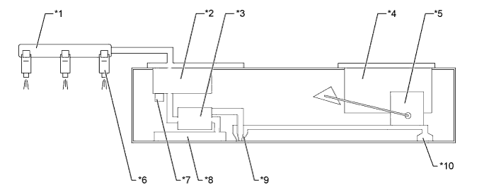
Text in Illustration *1 Fuel Delivery Pipe *2 Fuel Filter *3 Fuel Pump *4 Canister *5 Fuel Injector Assembly *6 Fuel Pressure Regulator Assembly *7 Fuel Pump Filter *8 Fuel Pump Filter *9 Jet Pump *10 Suction Tube
-