БЛОК ДВИГАТЕЛЯ ДЕТАЛЬНОЕ ОПИСАНИЕ
-
CONSTRUCTION
-
Cylinder Head
-
The cylinder head is made of aluminum alloy.
-
The intake manifold is integrated the cylinder head to realize compact design.
-
The injector is located near the center of the combustion chamber to promote the mixture of fuel and air.
-
A water jacket consists of the 2-stage construction to realize excellent cooling performance.

-
-
Cylinder Block
-
The cylinder block is made of aluminum die-cast.
-
A compact block has been achieved by producing the thin cast-iron liners and cylinder block as a unit. Do not bore the block with this liner.
-
The liners are the spiny-type, which have been manufactured so that their casting exterior forms a large irregular surface in order to enhance the adhesion between the liners and the aluminum cylinder block. The enhanced adhesion helps improve heat dissipation, resulting in a lower overall temperature and heat deformation of the cylinder bores.
-
Cylinder block water jacket spacers are used in the water jackets of the cylinder block sub-assembly. They suppress the water flow in the center of the water jackets, guide the coolant above and below the cylinder bores, and ensure uniform temperature distribution. As a result, the viscosity of the engine oil that acts as a lubricant between the bore walls and the pistons can be lowered, thus reducing friction.

-
-
Oil Pan
-
The oil pan is made of aluminum die-cast.

-
-
Piston
-
The pistons are made of aluminum alloy.
-
The combustion chamber is provided on the piston for direct injection.
-
A cooling channel is provided to realize excellent piston cooling performance.
-
A cast iron ring carrier is used to realize excellent wear resistance.
-
The piston skirt is coated with resin to reduce friction.
-
Full floating type piston pins are used.

-
-
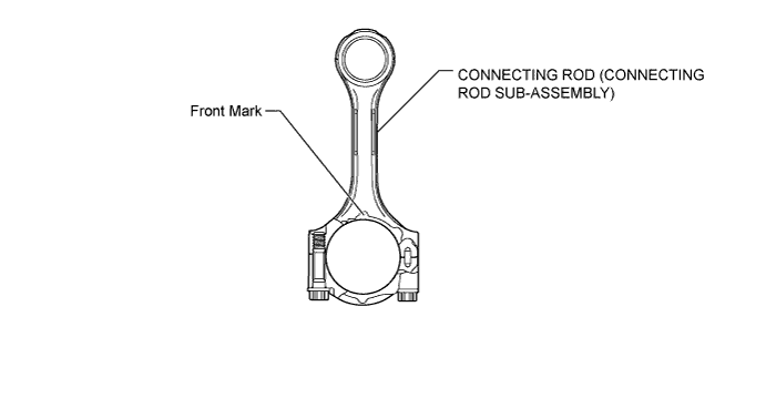
Connecting Rod
-
The connecting rods and caps are made of high strength steel for weight reduction.
-
-
Crankshaft
-
The crankshaft has 5 journals and 4 balance weights.
-
The crankshaft is made of forged steel.

Text in illustration *1 No.1 Journal *2 Balance Weight *3 Oil Hole *4 No.5 Journal
-
-
Crankshaft Pulley
-
The crankshaft pulley hub is made of cast-iron.
-
The Ethylene Propylene Diene Rubber (EPDM) material is used to the torsional damper rubber to realize high durability and reliability.

-
-
Valve Mechanism
-
The camshaft is driven by a timing chain. The camshaft drives the vacuum pump and supply pump in order to reduce the number of parts and realize a lightweight and compact design.
-
The intake and exhaust valves are opened and closed via the rocker arms.
-
The rocker arm consists of the rocker arm and roller.
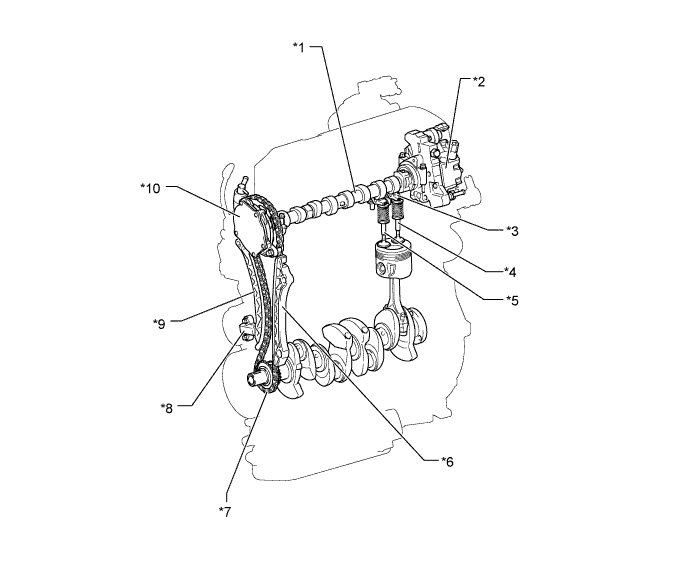
Text in illustration *1 Camshaft *2 Supply Pump (Injection or Supply Pump Assembly) *3 Rocker Arm (No. 1 Valve Rocker Arm Sub-assembly) *4 Exhaust Valve *5 Intake Valve *6 Chain Vibration Damper (No. 1 Chain Vibration Damper) *7 Timing Chain (Chain Sub-assembly) *8 Chain Tensioner (No. 1 Chain Tensioner Assembly) *9 Chain Tensioner Slipper *10 Vacuum Pump (Vacuum Pump Assembly)
-
-
Camshaft
-
The camshaft is made of cast iron.
-
The hollow type camshaft is used to realize lightweight.
-
The cam nose is hardened by induction heating to realize excellent durability.
-
A rib, by which the cam position sensor detects the camshaft position, is provided on the camshaft.
-
Oil holes are provided in the camshaft in order to supply engine oil to the rocker arm.

-
-
Rocker Arm and Valve
-
The rocker arm mechanism consists of the rocker arm, roller and adjusting screw.
-
Narrow valve stems are used to realize lightweight.

Text in illustration *1 Adjusting Screw *2 Roller *3 Rocker Arm (No. 1 Valve Rocker Arm Sub-assembly) - -
-
-
Timing Chain and Chain Tensioner
-
A bushed chain with 9.525 mm (0.375 in.) pitch is used to realize lightweight and maintenance-free operation.
-
An oil jet lubricates the timing chain.
-
The chain tensioner uses a spring and oil pressure to maintain proper chain tension at all times.
-
The chain tensioner suppresses noise generated by the chain.

Text in illustration *1 Timing Chain (Chain Sub-assembly) *2 Chain Vibration Damper *3 Chain Tensioner Slipper *4 Chain Tensioner (No. 1 Chain Tensioner Assembly) *5 Plunger *6 Main Spring
-
-