СИСТЕМА СНИЖЕНИЯ ТОКСИЧНОСТИ ОТРАБОТАВШИХ ГАЗОВ ДЕТАЛЬНОЕ ОПИСАНИЕ
-
FUNCTION OF MAIN COMPONENTS
-
The main components of the 1KR-FE emission control system are as follows:
Component Function TWC Oxidizes CO and HC in the exhaust gas and deoxidizes NOx at the same time, to purify them into CO2, H2O and N2.
Heated Oxygen Sensor The signal of the air-fuel ratio sensor changes abruptly between lean and rich at the stoichiometric air fuel ratio. Air-fuel Ratio Sensor Is used to determine the concentration of oxygen remaining in the exhaust gas. Has a characteristic where its output is proportional to the engine air fuel ratio. EGR Valve Opens and closes based on signals from the ECM and controls the flow rate of the exhaust gas in the EGR bypass. PCV Valve Opens and closes the valve using vacuum generated in the intake manifold and controls the flow rate of the blowby gas. VSV (for EVAP) Open and closes the valve based on signal from ECM and controls the flow rate of the evaporative emission. ECM
-
Controls the volume of fuel consumed based primarily on the signal from the air fuel ratio sensor, with minor corrections based on the signal from the heated oxygen sensor. This control optimizes the air-fuel ratio.
-
Regulates the EGR volume in accordance with the various sensor signals
-
-
-
SYSTEM CONTROL
-
EGR Control
-
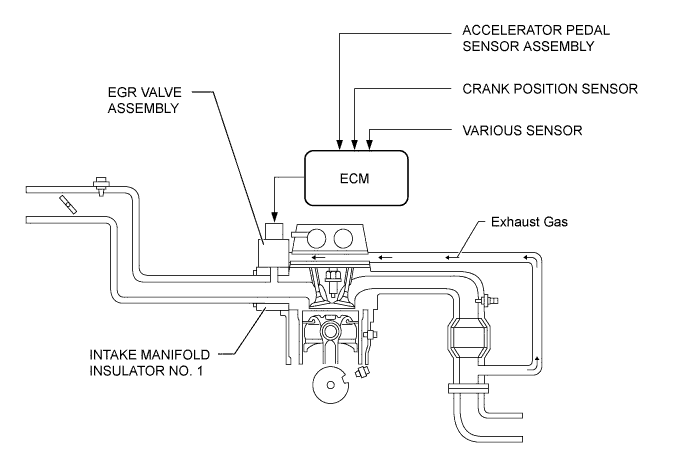
This system is designed to reduce and control NOx formation due to a slight reduction of the peak temperature in the engine combustion chamber, which is accomplished by introducing a small amount of inert gas into the intake passage.
-
By sensing the engine driving conditions and actual amount of the EGR valve opening, the ECM operates the EGR valve and throttle control motor, and regulates the amount of exhaust gas.
-
The exhaust gas passes through the cylinder head sub-assembly, and its flow volume is regulated by the EGR valve, and then is distributed to each cylinder via the intake manifold insulator No. 1 provided in between the cylinder head sub-assembly and the intake manifold.
-
-
Blowby Gas Ventilation System
-
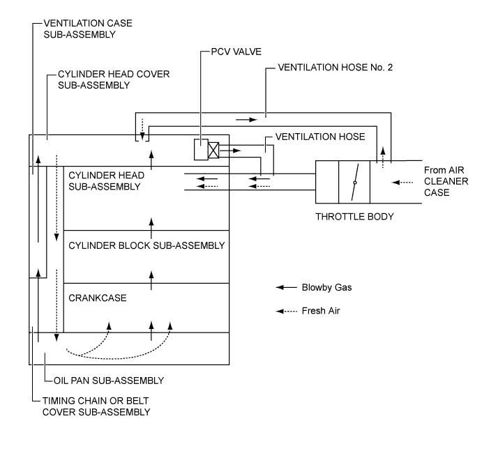
By introducing blowby gas that has a large amount of HC into the air intake side and burning it again, the system attempts to enhance the emission performance. Returning blowby gas volume is regulated to the appropriate amount corresponding to the engine operating conditions, reducing the engine oil quantity taken away and engine idling speeds.
-
The PCV (Positive Crankcase Ventilation) valve passage returns the blowby gas into the area after the throttle valve in accordance with the intake manifold vacuum.
-
When load is low, the passage from the cylinder head cover sub-assembly to the area before the throttle valve increases the air purification performance inside the crankcase by introducing fresh air, and when load is high, the passage circulates the blowby gas together with the PCV valve side passage due to the intake manifold vacuum.
-
To increase the ventilation efficiency, the blowby gas route has been divided into two channels; the crankcase side and the timing chain or belt cover sub-assembly side.
-
The ventilation case sub-assembly has been placed into the blowby gas passage between the cylinder head cover sub-assembly and the timing chain or belt cover sub-assembly in order to separate the engine oil from the blowby gas, so that the deterioration of the engine oil can be retarded as well as the oil consumption can be reduced.
-
-
-
CONSTRUCTION
-
TWC (Three-Way Catalytic converter)
-
TWCs are provided in the exhaust manifold and also in the front exhaust pipe assembly.
-
An exhaust manifold with an integrated TWC is used for warm-up of the TWC.
-
This TWC enables to improve exhaust emissions by optimizing the cells density and the wall thickness.
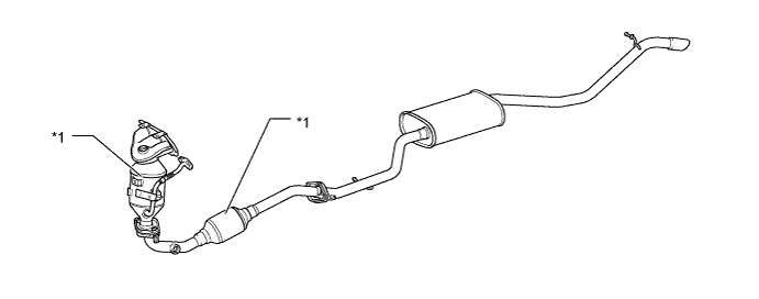
Text in Illustration *1 TWC - -
-
-
EGR Valve
-
A step motor is used on the EGR valve to enable the ECM to directly control the EGR valve.
-
The engine coolant circulates through the EGR valve to ensure proper cooling performance.
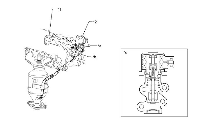
Text in Illustration *1 No. 1 Intake Manifold Insulator *2
-
EGR Valve Assembly
-
Step Motor
*a Water In *b Water Out *c EGR Valve Assembly Cross Section - - 
Exhaust Gas - - -
-
-