EXHAUST SYSTEM DETAILS
-
CONSTRUCTION
-
Exhaust Manifold
-
The exhaust manifold is made of stainless steel to reduce their weight and improve rust resistance.
-
The cooling holes have been provided on the heat insulator to cool down the exhaust manifold surface temperature, improving the durability.
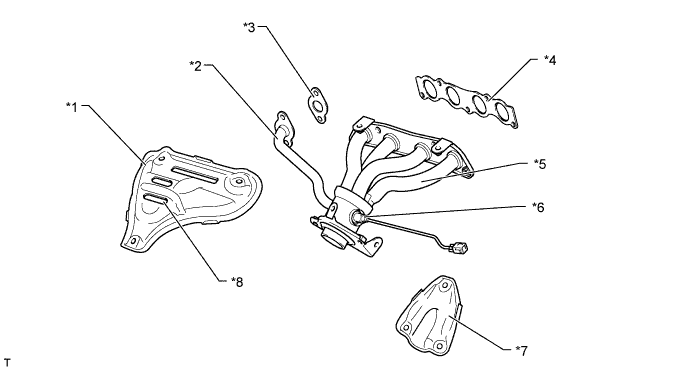
Text in Illustration *1 Heat Insulator
(Exhaust Manifold Heat Insulator No.1)
*2 EGR Pipe *3 EGR Inlet Gasket *4 Exhaust Manifold To Head Gasket *5 Exhaust Manifold *6 Air Fuel Ratio Sensor *7 Heat Insulator *8 Cooling Hole
-
-
Exhaust Pipe
-
The exhaust pipe is made of stainless steel in order to reduce the weight, improve the rust resistance, and enhance the TWC warm-up capability.
-
Ball joints are used to join the exhaust manifold to the front exhaust pipe, and the front exhaust pipe to the exhaust tail pipe. As a result, a simple construction and high reliability have been realized.
-
2 TWCs are provided at the front of the front exhaust pipe.
-
An exhaust heat recirculation system has been provided on the sub muffler in order to enhance the warm-up capability. As a result, the necessary engine warm-up time can be minimized by collecting exhaust heat into the engine coolant.
-
2-way exhaust control system is provided to reduce noise and vibration in the main muffler.
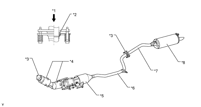
Text in Illustration *1 Exhaust Gas *2 Gasket *3 Ball Joint Portion *4 TWC *5 Sub Muffler *6 Exhaust Pipe Assembly Front *7 Exhaust Pipe Assembly Tail *8 Main Muffler
-
-
-
OPERATION
-
Exhaust Heat Recirculation System
-
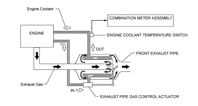
The exhaust heat recirculation system applies the heat of the engine exhaust to the engine coolant in order to enhance the heating performance at low temperatures, thus, the warm-up capability is further improved.
-
The exhaust gas control valve, which is operated by the exhaust pipe gas control actuator, is located in the front exhaust pipe assembly. The exhaust gas control valve opens and closes in order to change the flow of the exhaust gas in the front exhaust pipe assembly.
-
An engine coolant temperature switch, which is used only for the exhaust heat recirculation system, detects the temperature of the coolant flowing from the front exhaust pipe assembly.
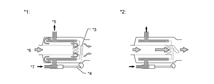
Text in Illustration *1 Valve is closed *2 Valve is open *3 Exhaust Gas Control Valve *4 Rod *5 Water OUT *6 Exhaust Gas *7 Water IN - -
-
-
2-Way Exhaust Control System
-
2-way exhaust control system is used. This system reduces the back pressure by opening and closing a variable valve that is enclosed in the main muffler, thus varying the exhaust gas pressure.
-
The valve opens steplessly in accordance with the operating condition of the engine, thus enabling a quieter operation at lower engine speeds, and reducing back pressure at higher engine speeds.
-
The control valve is enclosed in the main muffler. When the exhaust gas pressure overcomes the spring pressure, the control valve opens steplessly in accordance with the exhaust gas pressure.
-
When the pressure in the main muffler is low, the control valve closes. Hence exhaust gas does not pass the bypass passage, and exhaust noise is decreased in the main muffler.
-
When the engine speed and the back pressure in the muffler increase, the control valve opens. This allows a large volume of exhaust gas to pass through the bypass passage, thereby substantially decreasing the back pressure.
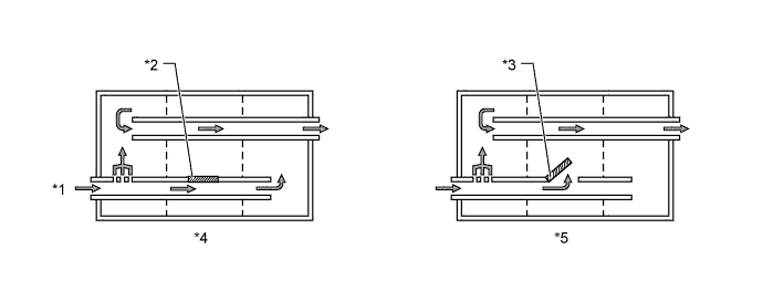
Text in Illustration *1 Exhaust Gas *2 Control Valve Closed *3 Control Valve Open *4 Low Engine Speed *5 Middle to High Engine Speed - -
-
-