EMISSION CONTROL SYSTEM DETAILS
-
FUNCTION OF MAIN COMPONENTS
-
The main components of the 2ZR-FXE emission control system are as follows.
Component Function TWC Reduces emissions by oxidation of CO and HC in exhaust gas and reduction of NOx. Oxygen Sensor This sensor detects the oxygen concentration in the exhaust emission by measuring the electromotive force which is generated in the sensor itself. Air Fuel Ratio Sensor As with the oxygen sensor, this sensor detects the oxygen concentration in the exhaust gas. However, it detects the oxygen concentration in the exhaust gas linearly. E.F.I. Vacuum Sensor Assembly Uses built-in semiconductors to detect the intake manifold pressure. EGR Valve Assembly* Operates when receiving signals from the ECM, regulating the EGR volume. EGR Cooler* Cools the exhaust gas temperature to improve the EGR efficiency. PCV Valve Opens and closes the valve using vacuum generated in the intake manifold and controls the flow rate of the blowby gas. Charcoal Canister Contains activated charcoal to absorb the fuel vapors that are created in the fuel tank. Purge VSV Opens and closes the valve based on the signal from ECM and controls the flow rate of the evaporative emission. ECM
-
Controls the volume of fuel consumed based primarily on the signal from the air fuel ratio sensor, with minor corrections based on the signal from the oxygen sensor. This control optimizes the air-fuel ratio.
-
Regulates the EGR volume in accordance with the various sensor signals.*
Tech Tips
*: Models with EGR System
-
-
-
SYSTEM CONTROL
-
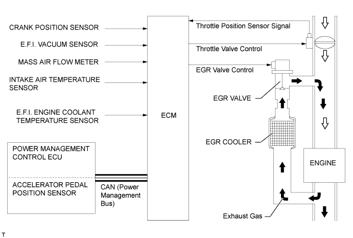
EGR Control (Models with EGR System)
-
In this system, a small amount of inert gas is allowed to flow into the intake passage, reducing the peak temperature in the engine combustion chamber.
-
By sensing the engine driving conditions and actual amount of the EGR valve opening, the ECM operates the EGR valve and throttle control motor, and regulates the amount of exhaust gas.
-
-
Blowby Gas Ventilation System
-
By introducing blowby gas that has a large amount of HC into the air intake side and burning it again, the system attempts to enhance the emission performance. Returning blowby gas volume is regulated to the appropriate amount corresponding to the engine operating conditions, reducing the engine oil quantity taken away and engine idling speeds.
-
An oil separator is provided in the blowby gas passage inside the cylinder block sub-assembly. This separates the engine oil from the blowby gas in order to reduce oil degradation and reduce the amount of engine oil consumed.
-
The PCV (Positive Crankcase Ventilation) valve passage returns the blowby gas into the area after the throttle valve in accordance with the intake manifold vacuum.
-
When load is low, the passage from the cylinder head cover sub-assembly to the area before the throttle valve increases the air purification performance inside the crankcase by introducing fresh air, and when load is high, the passage circulates the blowby gas together with the PCV valve side passage due to the intake manifold vacuum.
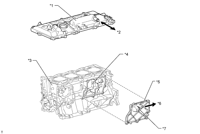
Text in Illustration *1 Cylinder Head Cover *2 To Air Cleaner Hose *3 Cylinder Block *4 Oil Separator *5 Oil Separator Cover
(No. 1 Ventilation Case)
*6 To Intake Manifold *7 PCV Valve - - 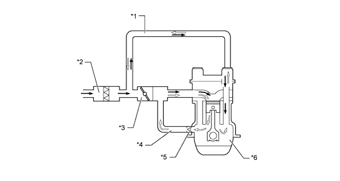
Text in Illustration *1 No. 2 Ventilation Hose *2 Air Cleaner Case *3 Throttle Body *4 No. 1 Ventilation Hose *5 PCV Valve *6 Crankcase 
Fresh Air 
Blowby Gas
-
-
-
CONSTRUCTION
-
TWC (Three-Way Catalytic Converter)
-
2 TWCs are provided on the front of the front exhaust pipe.
-
The TWC improves exhaust emissions through optimized cell density and wall thickness.
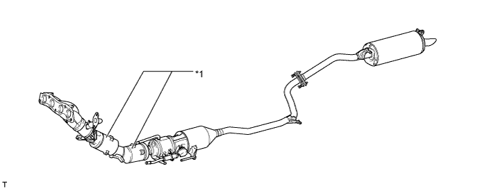
Text in Illustration *1 TWC - -
-
-
EGR Valve and EGR Cooler (Models with EGR System)
-
A step motor type EGR valve is used, precisely controlling the EGR gas flow amount.
-
The EGR cooler cools the exhaust gas temperature to improve the EGR efficiency.
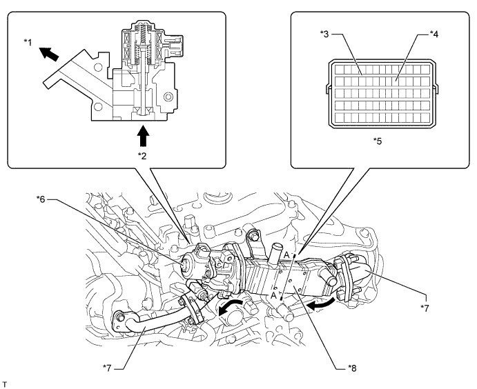
Text in Illustration *1 To Intake Manifold *2 From Exhaust Manifold *3 Water Passage *4 EGR Gas Passage *5 A - A Cross Section *6 EGR Valve Assembly *7 EGR Pipe *8 EGR Cooler EGR Gas - -
-
-
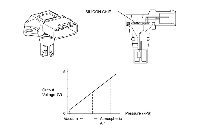
Vacuum Sensor
-
An E.F.I. vacuum sensor assembly is used to measure the intake manifold pressure for the emission control.
-
The E.F.I. vacuum sensor assembly consists of a silicon chip which utilizes the characteristics of a silicon chip that changes its electrical resistance when pressure is applied to it. The sensor converts the pressure into an electrical signal, and sends it to the ECM in an amplified form.
-
-