REAR SUSPENSION SYSTEM GENERAL
-
OUTLINE
-
A torsion-beam type suspension is used.
-
A rear axle carrier bush is obliquely mounted to obtain a toe-correct function, thus providing excellent driving stability and ride comfort.
-
Through the optimal layout of the suspension layout, the floor has been made low and flat, providing ample space at the back of the vehicle.
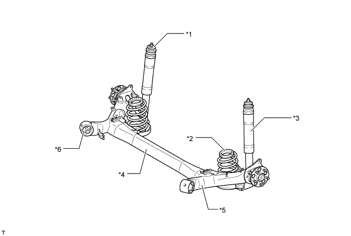
Text in Illustration *1 Rear Suspension Support *2 Rear Coil Spring *3 Rear Shock Absorber Assembly *4 Axle Beam (Rear Axle Beam Assembly) *5 Trailing Arm (Rear Axle Beam Assembly) *6 Rear Axle Carrier Bush Note
Be sure to use the jack-up points that are provided on the body when raising the vehicle on the jack. Never apply a jack under the axle beam, spring seat, trailing arm, or bushing of the rear suspension.
-
-
SPECIFICATION
Tire Size 195/65R15 215/45R17 Suspension Type Torsion-beam ← Rear Wheel Alignment (Unloaded Vehicle) Tread 1520 mm (59.8 in.) 1510 mm (59.4 in.) Camber -1°29' -1°28' Toe-in 2.8 mm (0.11 in.), 1.7 mm (0.07 in.)* 2.5 mm (0.10 in.)
-
*: Russian package or rough road specification models
-
-
MAIN FEATURES
-
Camber Change
-
In a torsion-beam type suspension, the camber angle and the toe change differ between the bouncing case and the tramping case, offering both straight-line stability and excellent cornering stability.
-
The same as the full-trailing arm type suspension, the axis that joins the center of the right and left bushings in the trailing arms is the center of movement during any same direction travel.
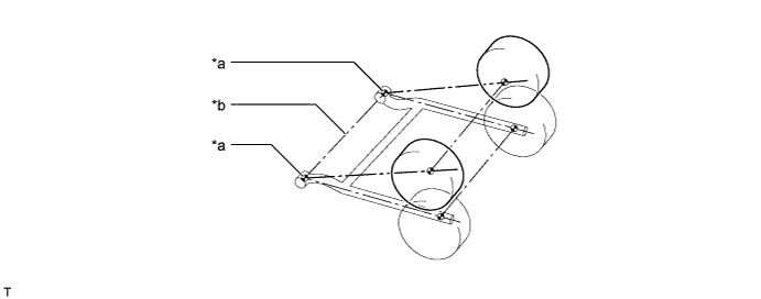
Text in Illustration *a Center of Bushing *b Axis of Movement -
During opposite direction travel, or if any difference in the suspension travel is created between the right and left wheels, the axle beam twists with its shearing center as the center of its rotation. Also, camber changes in relation to the suspension travel are determined by the ratio of the distance between the bushing in the trailing arm, the axle center and the shearing center ("α" in the figure below) and distance between the bushing in the trailing arm and the axle center ("L" in the figure below). Consequently, through the optimal allocation of the axle beam, the changes in the camber angle in relation to the suspension travel have been optimized, thus ensuring excellent cornering performance.
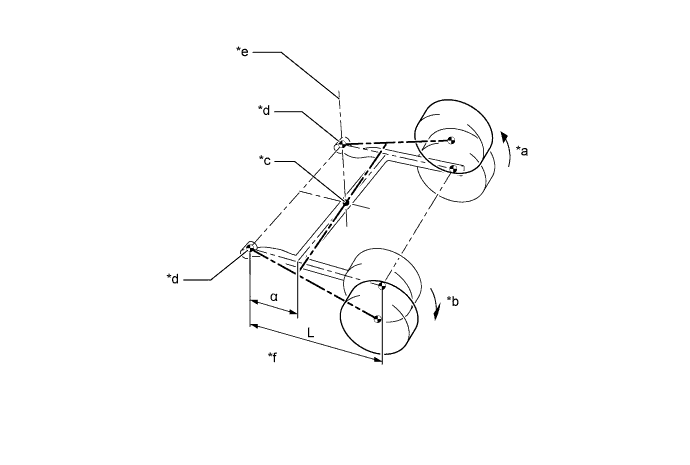
Text in Illustration *a Bound *b Rebound *c Shearing Center *d Center of Bushing *e Instantaneous Rotational Axis of Right Axle *f Camber Change Rate α/L
-
-
Anti-lift Geometry
-
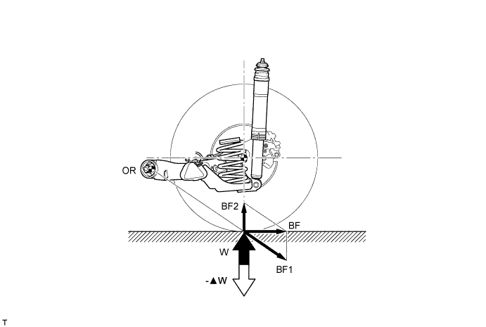
The lifting of the rear end of the vehicle during braking occurs due to the shifting of the center of gravity caused by inertia. The intersecting point (OR) supports the braking force (BF), and generates a force (BF1) in the direction of the intersecting point (OR) and a component force (BF2) in the direction of the ground contact. The force (BF1) can change the height of the intersecting point (OR). When the intersecting point (OR) is set high, it acts in the opposite direction (-▲W) of the load fluctuation (W) in order to restrain the lift.
-
-
Toe-correct Function
-
The longitudinal and lateral forces that are created in the vehicle during cornering cause the bushings in the trailing arms to deform. On a right turn, the right trailing arm moves forward and the left trailing arm moves rearward, creating a tendency for the left wheel to toe-out. In this situation, the bushings that are installed in the trailing arms are designed to utilize the lateral force, which is applied to the bushings during cornering, to correct the left trailing arm towards the toe-in direction.
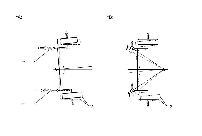
Text in Illustration *A Without Toe-correct Function *B With Toe-correct Function *1 Bushing *2 Left Wheel 
Bushing Movement 
Lateral Force 
Lengthwise Force 
Lateral Force Applied to the Bushing
-
-