FRONT SUSPENSION SYSTEM DETAILS
-
CONSTRUCTION
-
Front Suspension Support Sub-assembly and Front Coil Spring
-
A separate input construction type front suspension support sub-assembly is used.
-
This construction transmits only the inputs from the front shock absorber assembly and the front spring bumper via the front suspension support sub-assembly to the body. Thus, it achieves superior quietness and ride comfort performance.
-
The input is transmitted from the front coil spring via the strut mounting bearing to the body.
-
A pigtail type of front coil spring is used where the top and bottom diameters are different, creating a compact and lightweight construction. Lateral force reduction springs are used to control the reaction force line of the front coil spring, and reduce the bending force applied to the front shock absorber assembly. This reduces suspension friction, realizing a very comfortable ride.
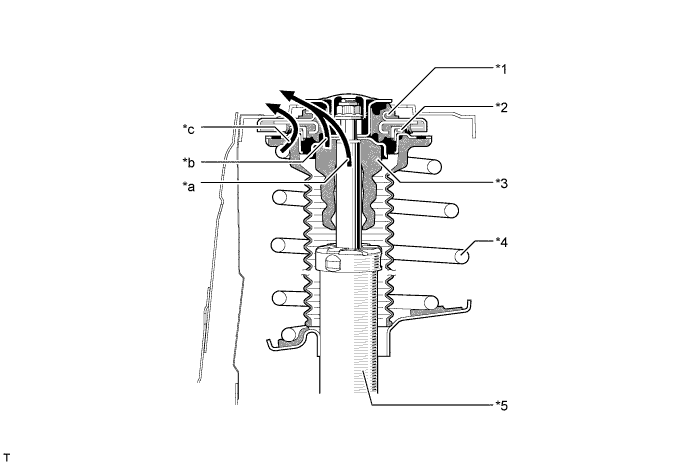
Text in Illustration *1 Front Suspension Support Sub-assembly *2 Strut Mounting Bearing *3 Front Spring Bumper *4 Front Coil Spring *5 Front Shock Absorber Assembly - - *a Front Shock Absorber Assembly Input *b Front Spring Bumper Input *c Front Coil Spring Input - -
-
-
Front Shock Absorber Assembly
-
In the front shock absorber assembly, a low-pressure N2gas sealed type construction is used to suppress cavitations and a multi-leaf type liner control valve is also used to attain the linear damping force characteristics, offering both driving stability and riding comfort.
Note
To prevent hazardous conditions, make sure to empty the gas from the shock absorber before discarding an N2gas sealed shock absorber. For details, refer to the Repair Manual.
-
Since the multi-leaf type linear control valve has a laminate-structure backing valve, it enables the damping force to be generated at lower piston speeds, compared with a structure that generates the damping force with only the base valve when compression force is applied.
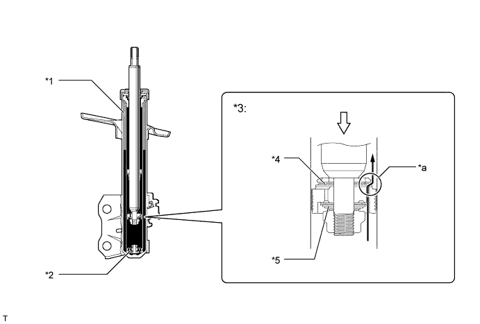
Text in Illustration *1 Low-pressure N2Gas
*2 Base Valve *3 Multi-leaf Type Linear Control Valve *4 Backing Valve *5 Inner Valve - - *a Damping Force - - 
Oil Flow 
Compression Force -
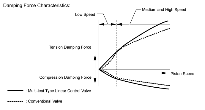
The illustration below shows a comparison of multi-leaf type linear control valve and conventional valve damping force characteristics.
-
-
Front Lower Suspension Arm
-
An L-shaped front lower No. 1 suspension arm, of which the cross section structure is closed, has been provided. As a result, in addition to the material thickness having been made thinner, the cross section and arm shape have been optimized, thus, achieving both a light weight and high rigidity at the same time.
-
Along with the use of wider treads, the length of the front lower No. 1 suspension arms has been extended.
-
The installation point of the lower arm bush and the bushing characteristics have been optimized to achieve excellent ride comfort and steering characteristics.
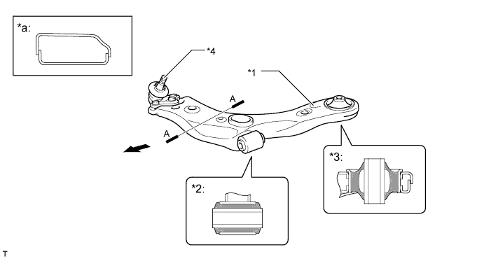
Text in Illustration *1 Front Lower No. 1 Suspension Arm *2 Front Lower No. 1 Arm Bush (Cross Section) *3 Front Lower No. 2 Arm Bush (Cross Section) *4 Front Lower Ball Joint Assembly *a A-A Cross Section - - Front - -
-
-
Front Stabilizer Bar
-
The front stabilizer bar is hollow, reducing the weight. A ball joint is used between the front stabilizer link assembly and the front stabilizer bar, and between the front stabilizer link assembly and the front shock absorber assembly. This helps reduce suspension friction and increase link rigidity. As a result, the ball joints perform effectively even for slight rolling and maintain stable roll feeling.
-
Aluminum front stabilizer bar assembly is used to achieve weight reduction.
-
The front stabilizer bar bushes are embedded in the suspension member to enable the front stabilizer bar to be placed efficiently. Also, on non-Russian package models, by adding dimples to the inner surfaces of the stabilizer bar bushes where the stabilizer bar comes into contact with it, sliding resistance is reduced, providing smoother ride comfort.
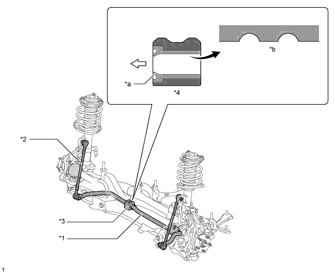
Text in Illustration *1 Front Stabilizer Bar *2 Front Stabilizer Link Assembly *3 Front Stabilizer Bar Bush *4 Cross Section of Front Stabilizer Bar Bush (Not applicable to Russian package models) *a Dust Lip *b Dimpled Surface Outward Direction - - Note
-
The shape of the front stabilizer bar bushes differs between the left and right sides.
-
To install the front stabilizer bar bushes on the vehicle, face their dust lips outward of the vehicle.
-
-
-
Suspension Member
-
A pressed-steel suspension member has been provided.
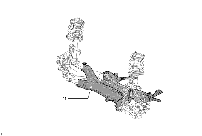
Text in Illustration *1 Suspension Member (Front Suspension Crossmember Sub-assembly) - -
-
-